
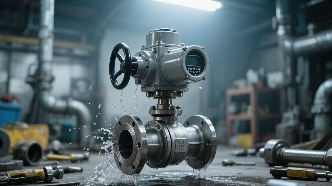
Ball valve field installation needs to ensure horizontal or vertical direction deviation is less than 1°, flange bolts according to diagonal divided into 3 times evenly tightened to 100% of design torque, before installation clean pipeline impurities, pigging test ensures unobstructed, after installation with 1.1 times working pressure perform sealing test, leakage rate must be lower than standard requirements, ensuring opening and closing is flexible without jamming.
valve positioning
Operating Space & Height
DN50 ball valve handle length is usually between 160 mm to 230 mm. Switching action needs 90 degree fan-shaped rotation space. Handle end distance from wall or adjacent pipeline should be greater than 50 mm.
DN100 and above specification ball valve handle length exceeds 450 mm. Opening torque can reach 80 Newton meters. Valve positioning needs on handle outer side leave out 150 mm maintenance position. When rust jamming needs use 500 mm long F-type wrench auxiliary force.
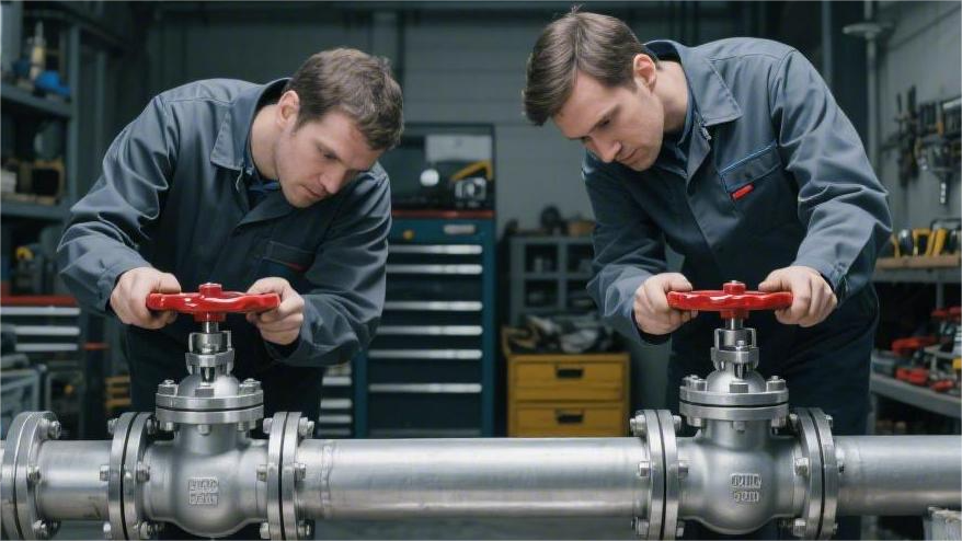
Inside pipe gallery side-by-side installed multiple valves, center distance should be greater than handle length 1.2 times. Two DN80 ball valves center distance suggestion set to 400 mm.
Operating height should be controlled at 1.2 meters to 1.4 meters. Adults utilizing body weight downward pushing handle can output about 400 Newton instantaneous tangential force.
- 1.2 meters: Frequent switching golden height, arm swing amplitude natural.
- 1.8 meters: Handle end needs vertical downward, line of sight needs looking up at opening plate.
- 0.5 meters: Needs half-squat operation, spine force uneven, strictly prohibited install long-handle valves.
- 2.2 meters: Requirements set 600 mm wide platform, edge set 100 mm toe board.
Valve weight if exceeds 50 kg, flange both sides within 300 mm should set fixed support pier. Support pier can offset switching moment generated mechanical torque. Pipeline producing 5 mm above horizontal displacement will tear internal sealing gasket.
Inside pipe trench valve centerline should be raised to bottom surface 300 mm above. Pit accumulated water soaking valve stem bottom will lead to stuffing box within 24 months occur electrochemical corrosion. Outside pit long hook operation, handle and ground angle should be at 15 degrees to 30 degrees.
Angle greater than 45 degrees when operation hook extremely easy slip off. Angle too small will reduce lever arm conversion efficiency. Valve ball staying at half-open position will cause sealing ring within 150 hours be high-speed fluid destroyed.
Actuator cable interface needs downward arrangement prevent accumulated water. Pneumatic actuator top higher than valve body centerline 300 mm to 600 mm. Side air pipe joint needs reserve 100 mm bending radius. Junction box front needs have 0.5 meter maintenance area.
- 350 mm: Electric actuator distance from wall, ensure manual handwheel pull-out space.
- 500 mm: Pneumatic cylinder disassembly clearance, strictly prohibited close-fitting machine room roof beam installation.
- 45 degrees: Actuator diagonal installation upper limit, exceeding limit will cause valve stem seal single side wear.
50 mm thick aluminum silicate insulation layer makes valve outer diameter increase 100 mm. Positioning stage should reserve insulation cotton thickness. High-temperature pipeline needs select long-neck valve, make packing gland higher than insulation shell 80 mm.
Long neck can dissipate pipeline residual heat. Actuator circuit board environment temperature needs lower than 60 degrees Celsius. Technical personnel need see clearly packing place whether has trace steam leakage.
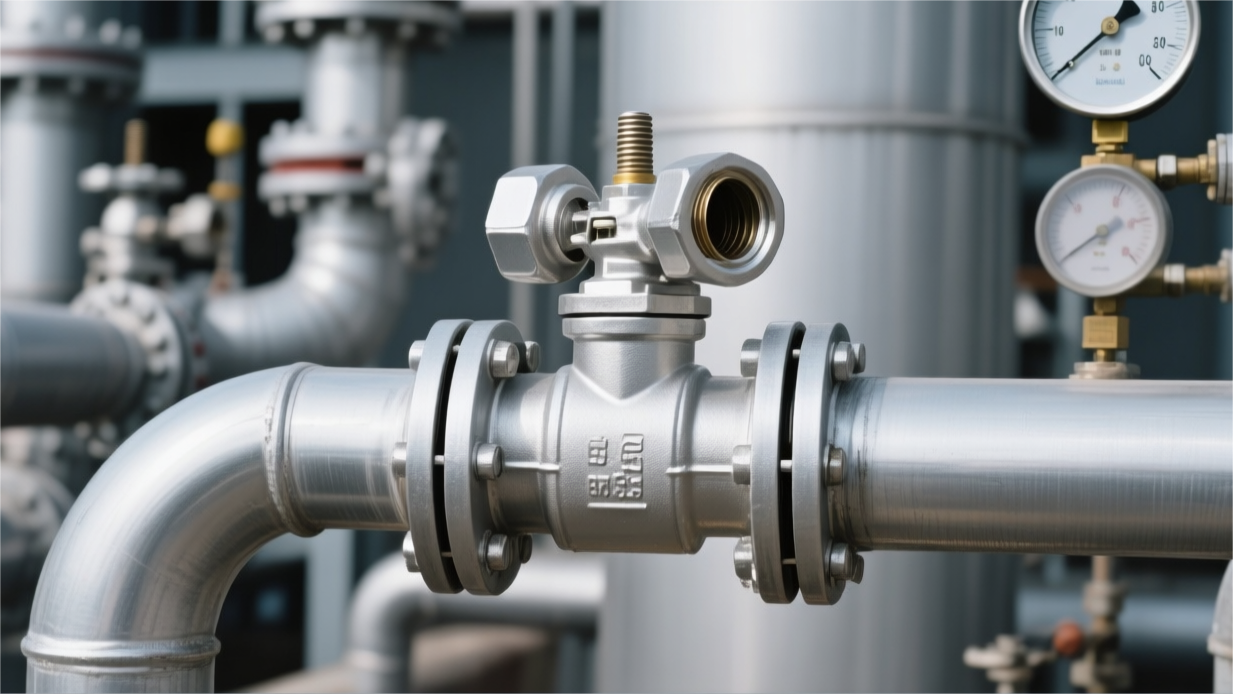
Installation position should avoid fluid turbulence zone. Distance from 90 degree elbow should have 6 times nominal pipe diameter straight distance. 5 meters per second flow velocity generated turbulence will lead to valve ball high-frequency vibration. Bracket bolts will within 12 months due to vibration loosen.
Flange gap before tightening should evenly maintain at 3 mm to 5 mm. One side 2 mm other side 6 mm will cause valve body axial distortion. Valve body producing 0.1 mm deformation will lead to ball switching feeling abnormally heavy.
- 0.2 mm: Flange sealing surface plane maximum concave-convex deviation upper limit.
- 1.0 mm: Bolt hole coaxiality deviation, prevent bolt receiving extra shear force.
- 120 Nm: DN100 flange bolt initial tightening torque, needs divided into three times diagonal force.
Outdoor salt spray environment thread should apply molybdenum disulfide grease. Putting on plastic anti-corrosion cap can protect thread not rust. After 5 years equipment overhaul no need gas cutting destroy pipeline.
Completion stage use feeler gauge check valve stem bracket gap. Even 0.1 mm gap proves no lateral squeezing stress. Valve operating life can reach manufacturer nominal value 1.5 times.
Operating space insufficient will lead to maintenance when must cut whole segment pipeline. Every place extra left 10 cm space can save subsequent 80% disassembly time. Manual ball valve handle should apply bright yellow paint.
Valve Stem Pointing & Angle
In DN80 specification pipeline, vertical deviation controlled within 5 degrees, can ensure ball center and valve seat sealing ring coincidence reach 99.8%. This posture utilizes gravity make fluid inside particulate matter deposit at valve cavity bottom, avoid 0.5 mm above hard impurities enter valve stem stuffing box.
When valve stem deviates from vertical axis exceeding 15 degrees, packing gland force balance is destroyed. Experimental records show, located at horizontal position valve stem, its lower half part sealing component bears static pressure than upper half part high out 12%. Operating 2000 cycles after, horizontal installed ball valve occurring packing place micro-leakage probability than vertical installation high out 35%.
- 0 degree (vertical upward): Stuffing box not subject to impurity siltation influence, sealing life extended to 50,000 times opening and closing.
- 90 degree (horizontal pointing): Suitable for space net height insufficient 1 meter working condition, needs every half year check once lubricant grease thickness.
- 180 degree (vertical downward): Belongs to error operation, pipeline inner wall peeling off oxide scale will directly damage valve stem seal.
- 45 degree diagonal insertion: Mostly used for multi-layer pipe gallery side-by-side, needs matching use with dust ring special bracket.
In handling containing 2% concentration solid particles medium when, inverted installed ball valve will within 48 hours appear jamming. Valve stem root groove will accumulate diameter 0.2 mm sand, at opening moment generate radial shear force. This force enough at 316L stainless steel valve stem surface scratch out depth 0.1 mm groove, leading to irreversible medium outward seepage.
| Valve Stem Installation Angle | Packing Force Deviation Value | Suggested Maintenance Cycle | Impurity Accumulation Risk Level |
|---|---|---|---|
| Vertical Upward (0°) | < 2% | 24 months | Extremely Low |
| Horizontal Pointing (90°) | 10% – 15% | 12 months | Medium |
| Downward Tilt (>135°) | > 25% | 3 months | Extremely High |
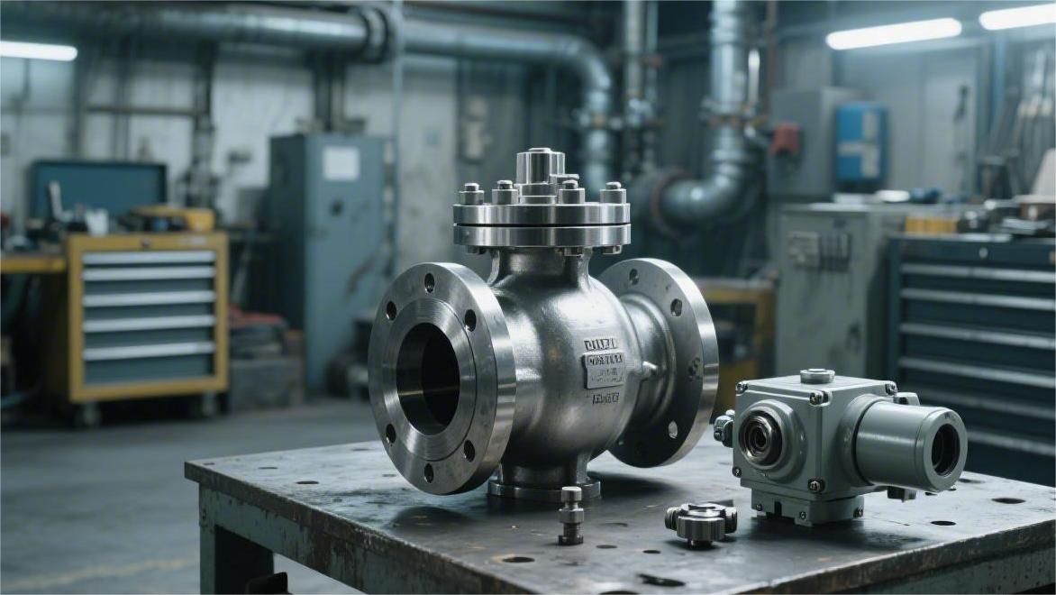
DN200 ball valve with electric actuator total weight about 120 kg, center of gravity deviates from centerline 250 mm. If not add auxiliary tray, valve stem will produce 0.05 mm micro-amount bending, leading to opening/closing torque from standard 150 Nm soar to 210 Nm.
Large diameter valve at horizontal positioning when, valve seat bottom flow velocity will than top slow 0.3 m/s. This flow velocity difference will lead to valve cavity bottom appear dead zone, siltation thickness exceeding 10 mm mud. Construction personnel should at valve body bottom blowdown hole place install DN15 discharge valve, weekly perform once with-pressure flushing.
Installing positioning sleeve when, concentricity error should be controlled at 0.1 mm. If angle offset leading to connection place produce 3 degrees above angle, driver output torque will have 15% transform into lateral squeezing stress, leading to actuator internal gearbox within 18 months produce fatigue cracks.
- 100 mm: Valve stem gland and nearest obstacle avoidance distance, ensure gland nut has 180 degree wrench swing space.
- 30 degree: With handwheel actuator diagonal installation angle upper limit, exceeding this limit operator will unable effectively apply thrust.
- 2 mm: Valve stem subject to heat elongation compensation value, at 200 degrees Celsius working condition needs reserve this gap prevent squeezing dead sealing pair.
Targeting high-temperature thermal oil pipeline, valve stem should point to diagonal upward 30 degrees to 45 degrees. This angle helps valve stem heat dissipation, make actuator connection place temperature than valve body surface low 40 degrees Celsius. Operating data shows, this positioning method can self-lubricating shaft sleeve chemical aging speed reduce 50% above.
Underground pipe gallery ball valve strictly prohibited valve stem horizontal extension into walkway. Standard width 1.2 meters inspection channel, valve stem end needs retract to pipeline envelope line inside 150 mm. Operators in emergency escape when, protruding valve stem will become hook hanging clothing safety obstacle, and extremely easy be handling tools hit leading to bending.
In low-temperature liquefied gas pipeline, extended type valve stem must vertical upward installation. Gas phase space thickness should maintain at 150 mm above, prevent low-temperature liquid directly contact stuffing box. If angle offset leading to cold liquid enter packing area, sealing component will at minus 100 degrees Celsius rapidly occur vitrification brittle fracture, causing large scale leakage.
Bolt tightening after centering check needs use dial indicator. Around valve stem rotate one circle, reading jump should be less than 0.08 mm. Data exceeding standard usually flange connection produced forced stretching stress. This stress will transmit to ball center, make sealing ring one side subject to pressure thin 0.2 mm, leading to valve closure not tight.
For equipped with limit switch ball valve, detection feedback arm installation angle must with valve stem completely synchronous. 90 degree full open position and 0 degree full close position signal error should be controlled within 0.5 degree. Positioning not accurate will lead to control room display already closed dead, while actual ball still leaves 2 mm wide tiny gap, producing continuous internal leakage scouring.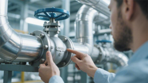
bolt tightening
Torque Calculation Foundation
ASTM A193 B7 grade bolt yield strength at 725MPa around. Field tightening usually takes 60% to 70% of this indicator as target load.
Torque calculation formula is T = K x D x F. Where T represents torque (Nm), K is friction coefficient, D is bolt nominal diameter (m), F is preload (N).
Dry bolt K value about 0.20. Applying light engine oil after reduced to 0.18. Using professional lubricant containing molybdenum disulfide, K value can drop to 0.12 around.
If a set of flange calculation when according to lubricated state set torque, actual construction yet dry tightening, generated preload will shrink 40% above. This torque loss will lead to gasket specific pressure insufficient, pipeline after pressure rise immediately occur seepage.
Conversely, if after calculating dry tightening torque privately apply high-efficiency lubricant, bolt received tension will exceed design value 50%. This will make bolt enter plastic deformation zone, length permanently stretched, losing like spring-like spring-back compensation capability.
1 meter long power bar applying 100 Newton force, generated torque is 100Nm. In these 100 units energy, approximately 50% consumed on nut and flange surface end-face friction, another 30% to 40% loss on thread pair friction.
Truly transformed into axial tension energy often insufficient 15%. Thread cleanliness every time becoming worse a bit, flange received actual compression force will cliff-like drop. Cleaning rust and sand on thread can save back about 20% energy efficiency.
Bolt subject to heat will produce physical elongation. Carbon steel bolt thermal expansion coefficient is 11.7 multiplied by 10 to power of -6. At 200 degrees Celsius working condition, 100mm long bolt will elongate 0.117mm.
- Bolt steel stamp must face outward, convenient later checking B7 or B8M material.
- Nut screwed in after, exposed thread should maintain at 2 to 3 pitches.
- Measuring flange gap, circle four points deviation needs controlled within 0.25mm.
- Gasket centering deviation must not exceed 1.5mm, prevent obstructing fluid causing scouring.
DN100 nominal diameter Class 150 ball valve, standard configuration 8 pieces 5/8 inch bolts. Using lubricated carbon steel bolts, single piece recommended torque usually set at 120Nm to 150Nm between.
If replaced by A193 B8 grade stainless steel bolt, because its yield strength lower than carbon steel B7 grade, torque value usually needs downward adjust 30% around. Not distinguishing material directly applying force, will lead to stainless steel thread occur cold welding biting dead.
Gasket also exists compression load requirement. Flexible graphite spiral wound gasket usually needs reach 70MPa above compression stress then can fill flange texture. Calculated total torque must ensure can provide greater than this value sealing force.
First round tightening applying 30% torque after, should focus check flange parallelism. At this time if find one side gap than other side large 0.5mm, must stop tightening, first adjust force lighter side bolt.
Divided into three rounds increasing torque (30%-60%-100%) is to give gasket internal fiber leave out displacement time. Non-metal soft gasket in after being pressed 24 hours within, will because stress relaxation lose away 10% to 15% preload.
High-temperature pipeline in operating 24 hours after, usually needs at no-pressure state perform hot tightening. At this time according to 100% target torque re-inspect. This step can compensate material subject to heat expansion caused about 20MPa preload loss.
- Using torque wrench before, check calibration certificate, validity must not exceed 12 months.
- Hydraulic wrench pressure gauge reading accuracy should be within 2%.
- Strictly prohibited at pipeline carrying pressure situation perform any twisting force on bolt.
- Narrow space using extension bar when, needs increase about 5% compensation torque value.
Thread pair inside if drop in one diameter 0.1mm sand grain, tightening moment friction resistance will increase 30Nm above. This false torque will deceive torque wrench, let you think tightened, actually bolt tension far not reached standard.
For DN300 above large diameter valve, bolt quantity as many as 12 to 20 pieces. At this time must adopt cross star-shaped sequence. If according to clockwise sequentially tighten, last few bolts force will than first piece high out 25% above.
Flange force uneven will lead to valve body produce micro-amount deformation. For high-precision ball valve, flange surface if produce 0.05mm deviation, then possible lead to ball and valve seat contact load occur offset, leading to internal leakage.
Tightening Procedure
Manual pre-tightening stage, flange gap at circumference various places deviation cannot exceed 0.5mm. Prepare one range covering target value 1.5 times torque wrench.
Taking 12-hole flange as example, 12 o’clock position marked as No. 1, tightening sequence jumps to 6 o’clock (No. 7), then turns to 3 o’clock (No. 4) against 9 o’clock (No. 10). This diagonal operation can offset flange face 30% above warping stress.
First round loading rated torque 30%. After operating use feeler gauge measure. If 12 o’clock position gap is 4.2mm, while 6 o’clock position is 3.8mm, deviation reaches 0.4mm, exceeded 0.25mm industry tolerance. Need micro-adjust bolt force.
Second round lifting to 60% torque, at this time gasket compression amount accounts for total deformation amount 70% around. Third round reaching 100% preset value, bolt enters steady state stretching. Regarding DN150 flange, single piece bolt loading duration should maintain at 5 to 10 seconds.
Use 100% torque again tap every piece nut. Usually in this round, about 20% bolts will because adjacent position tightening caused stress release and produce micro-rotation.
| Stage | Torque Percentage | Measurement Focus | Allowable Deviation Value |
|---|---|---|---|
| Pre-tightening | Finger strength | Thread smoothness | No block sense |
| First round | 30% | Flange four corners gap | < 0.25mm |
| Second round | 60% | Gasket extrusion situation | Evenly outward |
| Third round | 100% | Bolt elongation amount | 0.01mm level |
| Inspection | 100% | Circumference stress balance | Nut no longer displace |
Stainless steel bolt B8M when subjected to force friction generates heat fast. Continuous tightening 5 pieces above, thread temperature can rise to 60 degrees Celsius above. If not matching with anti-seize agent, torque indicated value possible in false increase, actual pressing force yet lower than setting value 40%.
Tightened bolt end part should higher than nut 2 to 3 thread pitches, about 4mm to 6mm. If thread exposed too long, explaining gasket possible being pressed flat deformation.
Medium temperature higher than 200 degrees Celsius when, bolt will appear creep. System operating 24 hours, flange preload often will lose 15%. At stop machine cooling down after, again perform supplementary tightening to 100% torque, can find back about 25MPa lost pressure.
| Flange Specification | Bolt Quantity | Single Rotation Degree | Gap Reference |
|---|---|---|---|
| DN50 Class 150 | 4 | 90 degrees/step | 3.5mm |
| DN100 Class 300 | 8 | 60 degrees/step | 4.8mm |
| DN200 Class 600 | 12 | 30 degrees/step | 6.2mm |
Using 150mm long joint when, actual action on nut force will attenuate about 7%. Calculating scheme when need multiply 1.07 correction coefficient, prevent because tool error lead to tightening force insufficient.
B7 material bolt under 100% load, every 100mm length usually elongates about 0.15mm. Data deviating this interval 20% when, explaining flange face exists non-parallel contact.
Spiral wound gasket V-type steel belt needs 50MPa to 80MPa initial specific pressure. Regarding DN100 pipeline, this requires bolt group provide total about 450kN tension force. Torque value if deviates 10Nm, corresponding specific pressure fluctuation can reach 5MPa.
Humidity exceeding 85% when, bare thread corrosion rate increases. Tightening after apply one layer anti-rust grease, can extend bolt integrity before next disassembly, reduce 30% maintenance man-hours.
DN250 ball valve single side flange has 12 pieces bolts, if among them 3 pieces tightening not in place, flange face sealing specific pressure will drop 25%. This situation when pipeline performing 0.6MPa airtightness test, extremely easy induce soap bubble test failure.
Carbon steel is 11.7 micron/meter·Celsius. In 300 degrees Celsius working condition, if not perform hot tightening, gasket surface contact pressure will from initial 60MPa drop to 35MPa.
If flange face has 1 degree tilt, bolt received additional bending stress will increase 15%. This eccentric load is main cause leading to M24 above large specification bolt occurring fatigue fracture.
Every interval 500 times opening/closing operation, should check bracket bolt torque. Ball valve opening/closing instantaneous produced torque fluctuation, will make bolt not added with spring washer produce about 5 degrees radial loosening, leading to valve stem centering degree deviate 0.1mm.
Establish construction database with DN, pressure grade, torque value as coordinates. Regarding repeatedly appearing leakage points, through data comparison can find whether torque setting value deviates from material yield point 60% interval.
Valve both ends flange force should maintain synchronization. Left side tightening completed while right side completely loose when, valve body internal ball center line will occur 0.02mm offset. This displacement will lead to PTFE valve seat produce non-symmetrical wear.
Using hydraulic torque wrench when, hose pressure should according to calculation table accurately adjust to 45MPa or 52MPa etc. fixed values. Every 500 times stretching cycles after, need re-calibrate hydraulic pump output accuracy, ensure torque output deviation within plus or minus 3% inside.
Gasket inner diameter should than pipe inner diameter large 3mm to 6mm. If tightening process inside gasket occurs eccentric displacement exceeding 2mm, fluid scouring produced turbulent flow will make bolt sensed vibration frequency increase, accelerate preload attenuation.
Regarding buried installation valves, bolt should select after Dacromet treatment anti-corrosion specification. Ordinary galvanized layer in underground humid environment, 2 years after thread pair friction coefficient K will from 0.15 rise to 0.28, leading to unable perform secondary disassembly.
High pressure Class 900 grade ball valve, bolt preload needs reach yield strength 75%. At this time must use ultrasonic force measuring instrument perform full inspection. Single piece bolt elongation amount if lower than 0.12mm, then regard this connection point as unqualified.
post-install inspection
Static Visual Review
Use feeler gauge measure flange between gap, reading distribution at 0°, 90°, 180°, 270° four points, each point deviation must be controlled within 0.2mm. If top gap is 3.5mm while bottom reaches 4.2mm, pipeline generated 0.7mm partial tension will squeeze PTFE valve seat.
Observe flange bolt sticking out length, nut outer end should expose 2 to 3 complete pitches, length about 5mm. If exposed part exceeds 10mm, bolt subject to environment temperature 100°C fluctuation caused linear expansion will change 15% preload.
- Bolt grade needs confirmed as 8.8 grade or A193 B7 grade.
- Gasket edge exposed width needs at 1mm to 2mm.
- Valve body surface WCB or 316 material steel stamp depth should be greater than 0.5mm.
- Flange surface between parallelism deviation must not exceed 0.1mm.
- Check 4 pieces valve cover bolts, tightening torque needs reach 40Nm.
- Handle limit block and valve body contact surface should reach 10 square millimeters.
Pipeline support bracket physical position needs distance from valve flange 300mm to 500mm between. For weight as much as 20kg DN80 ball valve, bracket can share 90% pipeline load, prevent valve body at 2.0MPa pressure under occur micron-level axis offset.
Manual ball valve operating radius inside should maintain 200mm clearance distance. Observe valve stem installation angle, vertical upward deviation must not exceed 15°. If valve stem horizontal installed, gravity will cause stuffing box below single side wear, leading to using 6 months after produce per minute 0.1ml outward leakage.
- Valve body coating thickness use thickness gauge confirm as 250 microns.
- Valve seat blowdown hole position at exactly downward 180° direction.
- Anti-static jumper copper wire cross-section area needs reach 6 square millimeters.
- Handle on open/close indication marker word height should be greater than 10mm.
- Confirm valve tag (TAG) size as 50mm by 80mm.
- Valve stem dust cover and gland matching gap needs less than 0.3mm.
Observe bolt head whether has marker pen drawn out 45° tightening calibration line. This mark can auxiliary judge whether nut at system vibration inside produced 3° above loosening. Not marked bolt at 1.6MPa cycle pressure under, exists preload dropping to initial value 70% possibility.
Check ball valve bottom blowdown plug, thread place should wrap 5 circles above PTFE raw material tape. Thread screw-in depth needs reach 12mm, ensure at 4.0MPa instantaneous impact pressure under, plug will not produce any naked eye visible wet trace.
- Valve actuator base 4 pieces bolts need full thread.
- Packing gland adjustment margin should reserve 3mm above.
- Valve stem connection place keyway matching tolerance needs controlled at 0.05mm.
- Nameplate marked CWP (working pressure) needs higher than system pressure 25%.
- Check handle sleeve, subject to 5kg pulling force when should not produce displacement.
- Valve ball surface at full open position should not observe 0.1mm depth scratch.
Verify valve body casting heat number and paper material certificate (MTR) 8-digit number. Consistent number can guarantee valve at 400°C environment physical strength. Beside valve hang green “Checked” aluminum tag, record down that day 25°C installation environment temperature.
Flange gasket material should confirmed as 316L spiral wound gasket or graphite gasket, outer diameter size needs with flange raised face completely coincide. Any exceeding 0.5mm radial misalignment, will at 1.0MPa airtight test stage cause per minute 2 above bubbles produced.
Operating handle from full open position rotate to full close position, confirm 90° stroke inside no any jamming. Handle end displacement distance should be fixed at 250mm around, ensure operator applying 150N thrust then can completely cut off medium, reach Class VI level sealing standard.
- Valve body flange thickness error should be controlled within 0.5mm.
- Confirm packing gland nut no 10 degrees above tilt.
- Valve stem exposed part lubricant grease thickness needs reach 1mm.
- Actuator air pipe joint place should apply 2 drops anti-loosing glue.
- Check worm gearbox oil level, window display needs reach 50% above.
- Flange jumper resistance value needs through multimeter measurement lower than 0.05 ohm.
Check valve surrounding 1 meter range inside escape route, ensure no diameter 50mm above obstacles. This space arrangement can within 5 seconds complete emergency shut-off, avoid fluid pressure fluctuation caused 0.5MPa overpressure risk.
Mechanical Operation Test
At pipeline not carrying pressure state when, use handle or actuator drive valve stem perform 3 to 5 times from full open to full close cycle rotation. Single time 90 degree rotation action should be controlled within 2 to 3 seconds inside complete, through palm sensing valve stem transmitted back vibration frequency. If rotation process appears exceeding 5Hz high-frequency quiver, usually represents valve seat and ball between sandwiched diameter 0.1mm above metal debris.
Observe handle end displacement trajectory, arc length should comply with pipe diameter proportion, for example DN50 ball valve 250mm handle, its end running arc length should accurately be 392mm. At rotating to 45 degree half-open position when, should feel no obvious torque mutation. If here operating torque instantaneous increase 20%, explaining ball roundness error exceeded 0.05mm process standard, this will shorten sealing ring 500 times above opening/closing life.
- Initial breakaway torque (Breakaway Torque) should not exceed operating torque 1.5 times.
- Handle rotate to 88 degrees when, limit pin should with block produce clear metal collision sound.
- Observe valve stem top scale line, full close position deviation must be less than 1 degree.
- Packing gland place friction resistance should be constant at 5Nm around.
- Valve stem up-down axial jump amount use dial indicator measurement needs lower than 0.1mm.
- Worm gearbox rotate 20 turns corresponding ball displacement should be accurate 90 degrees.
Manual operating torque reference table (based on room temperature PTFE seat):
| Valve Specification (DN) | Handle/Handwheel Length (mm) | Maximum Opening Thrust (N) | Rated Operating Torque (Nm) | Allowable Deviation Range |
|---|---|---|---|---|
| DN25 | 160 | 45 | 7.2 | +/- 10% |
| DN50 | 230 | 90 | 20.7 | +/- 12% |
| DN80 | 350 | 160 | 56.0 | +/- 15% |
| DN100 | 450 | 220 | 99.0 | +/- 15% |
Qualified ball valve at last 3 to 5 degrees closing angle inside, torque will because valve seat compression linearly increase. If last 10 degrees stroke no resistance feeling, explaining valve seat preload insufficient, at 1.0MPa pressure under extremely easy produce per minute 0.5 liter above through-type internal leakage.
Check limit screw locking state, two pieces M10 specification limit bolts should apply blue anti-loosing glue, and screw into bracket hole depth 15mm. Use angle gauge verify ball core diameter and pipeline inner wall coincidence, full open state under, pipe wall exposed step depth should not exceed 1.5mm. Any exceeding 2mm flow obstruction step will produce per second 5 meters above high-speed vortex, inducing pipeline produce 0.2mm amplitude physical shaking.
Adjust valve stem top packing gland nut, every time turning angle suggestion controlled at 15 degrees around. Over-tightening will lead to valve stem rotation friction temperature rise, at continuous operation 10 times after, packing place temperature if rise 5 degrees Celsius, then needs retreat 1/8 turn.
- Worm gearbox window inside lubricant grease filling amount should reach 70% volume.
- Drive shaft keyway matching gap needs use feeler gauge confirm as 0.03mm.
- Pneumatic actuator opening/closing time error should be controlled within 0.5 seconds.
- Manual/automatic switching handle clutch stroke should be at 20mm range.
- Observe indication arrow spray paint integrity, from 2 meters place should clearly identify open/close.
- Valve stem bottom thrust gasket thickness wear amount at first test when needs record as 0.
Connection place coaxiality deviation if greater than 0.2mm, lateral force will through valve stem transmit to ball, make one side valve seat bear exceeding rated value 30% pressure. This unbalanced force will make operating torque from initial 45Nm within three months climb to 70Nm.
Manual cranking torque if exceeds rated torque 1.2 times, explaining transmission chain or gear set exists dry friction. At 25 degrees Celsius environment under, to moving parts drip into 2 drops ISO VG 46 grade hydraulic oil, observe torque whether at 3 cycles after drop 10%, this is judging mechanical lubrication system whether reach standard evidence.
Ball surface roughness needs reach Ra 0.4 micron, mechanical test when through hand feeling check whether has scratch feedback. Place ball valve at 45 degree half-open position, naked eye observe ball edge and valve seat contact line, sealing line width should maintain at 3mm to 5mm between and circle distribution even. Contact line width inconsistency amount if exceeds 1mm, then predicts high-pressure environment under will occur non-symmetrical seepage.
Tightness Pressure Test
Connect pressure pump outlet hose to ball valve upstream flange, and at downstream flange install with 0.1MPa scale precision pressure gauge. Before pressure rise must rotate ball to 45 degree half-open position, make medium fill middle cavity and exhaust air. Remaining inside valve body air at under pressure when has 200 times of water compression rate, this will lead to pressure gauge pointer at test inside produce amplitude exceeding 0.2MPa irregular jumping.
Step-by-step start manual pressure pump, raise shell test pressure to nominal pressure 1.5 times. For PN16 grade ball valve, pressure gauge reading needs stabilize at 2.4MPa. In this state maintain 60 to 120 seconds, during use 500 lumen strong light flashlight irradiate valve body casting surface. Observe whether has diameter exceeding 0.1mm seepage point, or packing gland place whether exists per minute exceeding 1 drop overflow.
- Pressure gauge range should select test pressure 1.5 to 4 times, dial diameter not less than 100mm.
- Stainless steel valve test water chloride ion content must be controlled within 25ppm.
- Shell test when, valve stem packing place visible leakage rate must be 0.
- DN50 below valves, pressure holding time must not less than 15 seconds.
- Environment temperature change if exceeds 3 degrees Celsius, needs recalibrate pressure base value.
- Flange connection bolts at carrying pressure state under strictly prohibited perform 10 degrees above forced tightening.
Strictly prohibited in test area 5 meters radius inside stand people. High-pressure gas stored energy is same pressure liquid dozens of times, once 0.5mm sand hole occur physical burst, sprayed out fluid velocity will instantaneous exceed 340m/s, its impact force enough penetrate 10mm thick baffle.
Completion shell test after, drop pressure to nominal pressure 1.1 times perform sealing performance detection. Close ball valve, from downstream port observe sealing pair tightness degree. If adopting gas sealing test, pressure set at 0.6MPa then okay. At sealing surface apply concentration 10% soapy water, observe 1 minute inside bubble generated quantity. According to API 598 standard, metal seal ball valve allows has micro-amount bubbles, but soft seal ball valve must reach zero bubble escape A-grade standard.
If field environment temperature from morning 20 degrees Celsius rise to noon 28 degrees Celsius, closed middle cavity inside water heat expansion, will lead to gauge display pressure at 30 minutes inside naturally rise about 0.15MPa.
- Low pressure airtight test stability time suggestion set as 3 minutes.
- Sealing test should respectively from valve left, right two directions each perform once.
- Observe downstream outlet when, naked eye line of sight needs maintain with flange surface form 30 degree angle.
- For carrying pressure relief hole ball, should confirm relief direction toward high pressure side.
- Leakage rate calculation according to per minute generated diameter 2mm bubble count as standard.
- Test finished after, ball needs rotate 1 to 2 times to release cavity inside trapped pressure.
Every piece qualified ball valve at test finished after, must within 15 minutes sign pressure record sheet. Sheet needs record test pump number, starting pressure value (accurate to two decimal places) as well as during pressure holding pressure curve, this is equipment put into operation original physical evidence.
If at test inside find pressure gauge reading every 10 minutes drop 0.05MPa, needs prioritize check blowdown plug place seal. At 4.0MPa pressure impact under, thread connection place if only wrapped 3 circles raw material tape, extremely easy produce naked eye difficult perceive micro-seepage. Use torque wrench to M12 specification plug apply force to 45Nm, usually can solve 80% pressure fluctuation problem.
Check grease injection check valve steel ball whether reset, if steel ball is diameter 0.5mm sand grain jammed, high-pressure medium will through grease injection channel reverse flow out. This leakage often be mistaken for valve stem packing failure, processing method is use grease gun inject 2ml sealing grease perform forced physical sealing.
- Actuator cylinder test pressure should be set at rated air source 1.1 times.
- Observe pressure gauge pointer when, should continuously tap gauge shell 3 times to eliminate mechanical hysteresis.
- Valve seat sealing surface pressure drop within 15 minutes should not exceed initial value 1%.
- Draining water when should open bottom drain valve, ensure cavity inside residual moisture lower than 5ml.
- High pressure test pump rated flow not suitable exceed per minute 5 liters.
- Anti-static test should at pressure relief after perform, resistance value needs stabilize below 10 ohms.
Record down valve at 1.1 times pressure under operating torque change. Usually carrying pressure operation torque will than empty load when high out 30% to 50%. If a rated torque 40Nm ball valve at 2.0MPa pressure under operation torque soar to 100Nm, explaining internal valve seat self-lubricating coating already worn, or ball centerline and valve stem produced 0.2mm offset.

")