
Pressure ratings are typically selected between Class 150 and 2500;
Conventional body material is WCB carbon steel, while CF8M stainless steel is specified for corrosive media;
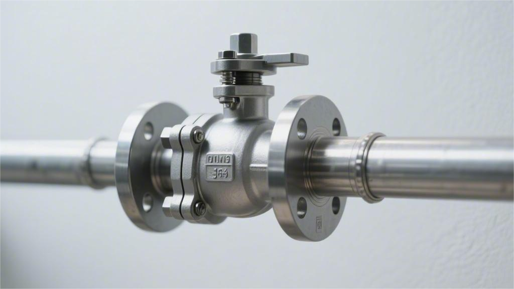
BW (Butt Weld) ends are recommended for high pressure, and RF (Raised Face) flanges for low pressure.
During installation and mating, flange bolts must be tightened in a diagonal sequence to ensure a leak-free seal.
Pressure Rating
In the ASME B16.34 standard, the pressure rating distribution for trunnion mounted ball valves ranges from Class 150 to Class 2500.
Taking the common ASTM A105 carbon steel material as an example, a Class 600 valve can withstand 1480 psi of pressure at 38°C; when the temperature rises to 427°C, the allowable pressure drops to 675 psi.
When selecting equipment, the piping design pressure must be added with a margin of at least 10%, and strictly compared against the P-T (Pressure-Temperature) rating charts to confirm that the valve rating aligns with the engineering parameters of the flanges and line pipes (e.g., API 5L X65).
ASME vs API
ASME B16.34 originates from the Boiler and Pressure Vessel Code and is a broad foundational document covering various industrial pressure-bearing valves from Class 150 to Class 4500.
API 6D is compiled by the American Petroleum Institute, specifically customized for long-distance oil and gas pipelines. Its scope of application is limited to a maximum of Class 2500, and it adds specific physical data and testing requirements unique to long-distance pipelines on top of ASME’s base parameters.
Taking a 24-inch Class 600 trunnion mounted full bore ball valve as an example, API 6D explicitly specifies that its minimum internal diameter must reach 590 mm (23.25 inches).
This dimensional tolerance is set to allow smart pigs inside the pipeline to pass through the valve cavity without obstruction. In contrast, ASME B16.34 only specifies the connection dimensional parameters for the flanges at both ends of the valve body, and does not establish mandatory physical data lower limits for the degree of bore reduction inside the valve cavity.
There are differences in the basis for calculating the metal wall thickness of the pressure-bearing shell. According to the appendix specifications of ASME B16.34, the actual measured wall thickness of a 12-inch Class 600 carbon steel (ASTM A105) forged valve body must not be less than 18.3 mm.
| Specification Comparison Item | ASME B16.34 Requirements | API 6D Requirements |
|---|---|---|
| Pipeline Pigging Capability | No specific requirements, standard reduced bore allowed | Must provide Full Bore option |
| Minimum Internal Diameter | Determined by manufacturer’s independent design | Appendix Table C provides the baseline internal diameter accurate to the millimeter |
| Base Wall Thickness | Calculated based on temperature and pressure ratings | Adopts ASME data and typically adds a 3.2 mm corrosion allowance |
| End Bevel | Complies with ASME B16.25 standard | Mandatorily complies with B31.4 or B31.8 specifications for long-distance pipelines |
For the pressure testing phase before valves leave the factory, API 6D sets a longer standard for pressure holding time. For valves with a nominal diameter of 10 inches or greater, the minimum holding time for the hydrostatic Shell Test required by ASME B16.34 is only 2 minutes.
Under the same 10-inch physical specifications, API 6D mandates that the holding time for the shell test be extended to 5 minutes. Engineers must use a chart recorder to capture the pressure decay curve at 1.5 times the rated cold working pressure and sign the test certificate.
The medium and pressure parameters for the Seat Test are completely different. The ASME specification allows routine testing using only water at 1.1 times the working pressure, whereas API 6D compulsorily adds a low-pressure gas testing phase.
Factory inspectors need to inject compressed air or nitrogen at 80 psi (approx. 0.55 MPa) into the valve cavity. Within a 2-minute holding period, according to the ISO 5208 standard, the leakage rate of a soft-seated trunnion mounted ball valve must achieve Rate A, i.e., 0 drops/minute.
- ASME Seat Test: 1.1 times the rated water pressure, focusing on basic isolation capability under high pressure.
- API Gas Test: 80 psi low-pressure gas, inspecting the initial seating tightness of the valve seat spring against the ball under low differential pressure.
- API High-Pressure Gas-Tight: For severe gas service, nitrogen at 1.1 times the rated pressure is applied, and bubble leakage must be zero.
Double Block and Bleed (DBB) functionality is a proprietary technical indicator for long-distance pipeline valves. API 6D clearly defines DBB as well as Double Isolation and Bleed (DIB-1 and DIB-2) physical testing protocols in separate sections.
According to API’s DBB testing procedures, water pressure is injected into the cavity and raised to 1.33 times the rated pressure. When the internal cavity pressure exceeds the spring preload force due to fluid thermal expansion, the Single Piston Effect (SPE) seats will automatically relieve pressure to both ends of the pipeline.
The opening pressure data when the relief action occurs must be recorded by high-frequency sensors, usually safely set between a differential pressure of 100 psi and 300 psi. The ASME B16.34 standard text completely lacks functional definitions regarding bi-directional sealing and middle cavity pressure relief such as DBB or DIB.
Ultra-high pressure oil and gas wellhead operating conditions will deviate from the API 6D standard and instead adopt the higher-tier API 6A specification. API 6A uses psi as the basic rating unit, covering 2000 psi, 5000 psi up to the ultra-high pressure 20000 psi level.
API 6A introduces the gradient concept of Product Specification Levels (PSL 1 to PSL 4). Under the PSL 3G level, trunnion mounted ball valves must undergo extreme nitrogen micro-leakage testing at full rated working pressure (e.g., 10000 psi).
The Non-Destructive Testing (NDT) coverage for metal materials increases exponentially as the PSL rating rises. PSL 3 requires 100% Ultrasonic Testing (UT) and Magnetic Particle Testing (MT) on all pressure-bearing forgings, and the retention of radiographic films for 10 years.
Conventional industrial water line valves under ASME specifications usually only conduct proportional sampling of materials according to the ASTM A388 standard. Only when the buyer provides additional Material Data Sheets (MDS) will ordinary ASME valves undergo full 100% flaw detection.
| Traceability and Testing Documents | Conventional ASME Order Standards | API Pipeline Project Standards |
|---|---|---|
| Material Test Reports | EN 10204 2.2 Declaration of Compliance | EN 10204 3.1 or 3.2 Physical and Chemical Report |
| Nameplate Identification Requirements | Laser-etched basic parameters | Must bear the official API Monogram |
| Operating Torque Data | Theoretical calculated values | Breakaway torque must be actually measured at full pressure prior to ex-works |
| Fugitive Emission Certification | Depends on buyer’s additional specification | Routinely included API 641 (Not exceeding 100 ppmv) |
API 6D mandates that manufacturers provide Material Test Reports (MTR) complying with the EN 10204 3.1 level, individually recording the ingot heat number, chemical composition ratios, and tensile yield strength.
The physical measurement of operating torque data is mandatorily included in the API 6D factory inspection checklist. Under unpressurized and fully pressurized conditions, workers use digital torque wrenches to record the actual breakaway torque required for stem rotation.
The fully pressurized breakaway torque for a 20-inch Class 900 trunnion mounted ball valve may reach up to 15,000 N·m. Based on the measured torque data, engineers then match a pneumatic actuator to the valve using a physical safety factor of 1.25 to 1.5.
The standard for controlling fugitive emissions at the Stuffing Box also differs. API 6D typically cites the API 641 standard, stipulating that after 100 mechanical open/close cycles in a methane medium, the leakage concentration at the valve stem must not exceed 100 ppmv.
Pressure-Temperature (P-T)
Engineers cannot apply the rated working pressure at ambient temperature to high-temperature operating pipelines. Taking ASTM A105 forged carbon steel as an example, it belongs to Material Group 1.1; in a 38 degrees Celsius (100 degrees Fahrenheit) testing environment, a Class 300 valve can safely withstand an internal fluid pressure of 740 psi.
As thermal energy from the pipeline medium is introduced, the yield strength of the internal metal lattice structure exhibits non-linear attenuation. When the operating temperature climbs to 260 degrees Celsius (500 degrees Fahrenheit), the maximum allowable working pressure for an A105 carbon steel valve body of the same thickness drops to 600 psi.
If abnormal operating conditions cause a temperature overshoot to 425 degrees Celsius (800 degrees Fahrenheit), the upper limit for carbon steel materials, the allowable pressure drops sharply to 410 psi, a decrease close to 45% of its ambient pressure-bearing capacity. The ratio of internal chemical components of the material determines the trend and slope of the thermal attenuation curve.
- Group 1.1 (A105 Carbon Steel): Withstands 740 psi at 38°C, drastically drops to 410 psi at the 425°C upper limit.
- Group 2.2 (316 Stainless Steel): Withstands 720 psi at 38°C, fast high-temperature attenuation, only allowed to withstand 425 psi at 425°C.
- Group 2.8 (2205 Duplex Steel): Withstands 750 psi at 38°C, limited by the ductile-to-brittle transition phase region, maximum temperature is set at 315°C.
The actual overall P-T curve of a trunnion mounted ball valve is jointly constrained by two independent physical boundaries. The first is the aforementioned metal shell pressure attenuation line, and the second is the thermal melting physical curve of the internal non-metallic seals. The maximum working temperature limit is always restricted by the lower of these two sets of test data indicators.
Trunnion mounted ball valves in industrial applications heavily rely on high-molecular polymers to achieve a zero-leakage fit between the seat and the ball surface. Polytetrafluoroethylene (PTFE) is a basic seat material; it has an extremely low coefficient of friction (0.04) at room temperature but undergoes severe plastic creep deformation when the pipeline temperature crosses the 150 degrees Celsius threshold.
Manufacturers blend 15% to 25% glass fiber or carbon fiber into the original PTFE powder (creating RPTFE) to resist material extrusion and deformation generated under high temperature and high pressure. The reinforced non-metallic seats raise the physical temperature limit to 200 degrees Celsius, effectively handling low-pressure industrial steam pipelines with pressures of 250 psi.
- Pure PTFE Soft Seat: Working upper limit of 150°C, suitable for conventional tap water and low-to-medium pressure natural gas transmission.
- Reinforced RPTFE Seat: Doped with 25% carbon fiber powder, physical limit raised to 200°C.
- PEEK Specialty Polymer: Extremely high mechanical yield strength, maintains stable resilient sealing at a high temperature of 260°C.
- Tungsten Carbide Coated Metal Seat: Completely abandons polymer materials, safely withstands extreme fluid high temperatures up to 538°C.
When fluid thermal energy crosses the physical threshold of 260 degrees Celsius, all conventional polymer valve seats will experience irreversible melting failure. Engineers abandon high-elasticity soft-seal designs and turn to Metal-to-Metal seat structures preloaded with Inconel 718 springs, combined with High Velocity Oxygen Fuel (HVOF) spraying to increase the surface hardness of the ball.
Besides the seats in the main fluid channel, the O-ring rubber seals around the stem and upper/lower trunnion pivots also have strict P-T range limit requirements. Fluoroelastomer (FKM/Viton) can maintain excellent elasticity at 200 degrees Celsius, but undergoes a glass transition at minus 29 degrees Celsius, completely losing its original cross-sectional resilience and causing hazardous media to leak outward.
For minus 46 degrees Celsius Propane Dehydrogenation (PDH) cryogenic pipelines, equipment uses Hydrogenated Nitrile Butadiene Rubber (HNBR), which has better low-temperature flexibility, coupled with an ASTM A350 LF2 low-temperature carbon steel forged valve body. The P-T considerations at this point shift from high-temperature pressure attenuation to impact toughness data of metallic and non-metallic parts in extreme cold environments.
According to ASTM A350 standard laboratory requirements, LF2 forgings in an extremely cold physical environment of minus 46 degrees Celsius must have an average Charpy V-Notch impact energy test value of no less than 20 Joules. Below the set kinetic energy absorption data, the pressure-bearing shell faces a physical risk of instantaneous brittle fracture when subjected to fluid water hammer impacts within the pipe.
- FKM (Viton) Fluoroelastomer O-rings: Applicable physical range is -29°C to 200°C.
- HNBR Low-Temperature Nitrile Rubber: Applicable physical range is -46°C to 150°C.
- FFKM (Kalrez) Perfluoroelastomer: Can stably withstand 327°C high temperatures and various strong corrosive chemical solvents.
- Lip Seal: Internally contains an Elgiloy alloy energy-storage spring, suitable for -196°C ultra-cryogenic environments.
In Liquefied Natural Gas (LNG) receiving terminals under cryogenic conditions, the liquid phase pipeline temperature is maintained at minus 162 degrees Celsius year-round. Ordinary elastomer rubber loses all deformation capability in this extremely cold state and shatters like glass. The system uses Polytetrafluoroethylene U-shaped rings (Lip Seals) encasing alloy springs to maintain the valve body’s dynamic physical seal.
Dimensional Matching
Taking a 12-inch Class 600 Raised Face (RF) flanged ball valve as an example, its standard Face-to-Face length dimension is rigidly specified as 838 mm.
Changes in the shape of the flange sealing face will lead to numerical deviations in assembly dimensions. If the same 12-inch Class 600 valve adopts a Ring Type Joint (RTJ) face, its End-to-End length will increase by 3 mm, reaching 841 mm.
According to API 6D engineering specifications, manufacturing tolerances for face-to-face dimensions are strictly limited. For ball valves with a nominal diameter less than or equal to 10 inches, the allowable physical length error margin is locked at ±1.5 mm.
Besides the external length, pipe flange pairing is highly dependent on the geometric bolt hole layout data specified by ASME B16.5. The standard outer diameter for an 8-inch Class 300 flange is 381 mm, with 12 bolt holes evenly distributed around the circumference, and the calculated Bolt Circle Diameter (BCD) is 330.2 mm.
Fastener dimensions must maintain a mechanical clearance fit with the flange hole diameter. For the aforementioned 8-inch Class 300 flange, where a single hole is drilled to 25.4 mm (1 inch), engineers need to select ASTM A193 B7 high-strength studs with a 7/8 inch outer diameter.
For heavy-duty piping systems exceeding 24 inches in diameter, the flange dimensional specification switches to ASME B16.47. This specification inherently contains two completely independent physical dimensional data systems, Series A and Series B, which cannot be interchange-bolted together.
Taking a 30-inch Class 300 pipeline as an example, a Series A flange has an outer diameter of 1092 mm and is distributed with 28 bolts of 1.25 inches in diameter. A Series B flange has its outer diameter reduced to 991 mm, the number of bolts increased to 36, and the bolt diameter decreased to 1.125 inches.
- ASME B16.5 Flange: Applicable range covers NPS 1/2 to NPS 24, it is the standard size for conventional piping units.
- ASME B16.47 Series A: Inherited from the MSS SP-44 specification, with thicker flange plates, matched with large-diameter heavy-load pipelines.
- ASME B16.47 Series B: Inherited from the API 605 specification, with thinner flanges but denser bolts, mostly used in confined installation spaces.
8-inch valves from Class 600 to Class 900 share the R49 octagonal gasket. The average pitch diameter of the gasket is 269.88 mm, and the depth of the flange ring groove needs to be precisely machined to 11.1 mm.
Trunnion mounted ball valves utilizing Butt Weld (BW) ends follow the ASME B16.25 standard for end bevel geometric parameters. The nominal wall thickness of a 10-inch Sch 40 pipeline is 9.27 mm, and the outer diameter of the valve body end is machined to 273 mm, forming a standard welding bevel of 37.5 degrees.
When the physical step difference between the valve inner diameter and the pipe inner diameter exceeds 1.5 mm, the specification requires machining a 1:3 internal taper transition zone on the thicker wall side to reduce fluid turbulence.
Schedule data determines the actual internal diameter dimension of the pipeline. For a 10-inch steel pipe with the same outer diameter of 273 mm, the internal flow diameter for Sch 40 is 254.5 mm. When the pressure rating rises and it is replaced with Sch 80, the inner diameter shrinks to 242.9 mm.
Misalignment of the inner diameter dimensions will trigger sudden physical changes in the flow velocity within the pipeline. In a high-pressure natural gas main with flow rates exceeding 5 m/s, a 2 mm inner diameter step without a 1:3 taper transition will generate local vortex stress and scour/corrode the weld root.
The internal cavity bore dimensions of trunnion mounted ball valves are provided with absolute data lower limits by Appendix C of the API 6D specification. For a 16-inch Class 600 Full Bore ball valve, the minimum measured diameter at any point in its internal flow path must not be less than 387 mm.
The cross-sectional area of the internal fluid passage for a Reduced Bore ball valve is one physical size smaller than the nominal pipe area. For a 16×12 inch reduced bore valve, its two end flanges match a 16-inch pipe, while the internal ball passage diameter is reduced to 289 mm.
Flange dimensions of the actuator connection surface follow the ISO 5211 general standard. For large-diameter ball valves with output torques exceeding 10,000 N·m, their Top Works connection plate adopts the F30 specification. The bolt circle diameter is 298 mm, distributing eight M20 threaded holes.
The geometric physical parameters of the stem drive end must achieve precise coordination with the actuator shaft hole. A cylindrical valve stem with an 85 mm diameter needs to have a flat keyway milled to a width of 22 mm and a depth of 14 mm, with machining tolerances restricted to within +0.05 mm.
- Full Bore Internal Diameter Baseline: The minimum flow path of a 24-inch Class 600 valve must reach 590 mm.
- Reduced Bore Flow Path Pressure Drop: When fluid passes through the sudden cross-section change area, the pressure loss is usually 3 to 5 times that of a full bore.
- Pigging Pass-Through Requirement: Mechanical obstruction of the internal flow path dimensions must not cause the pig driving differential pressure to rise by more than 15 psi.
Body Material
Conventional non-corrosive pipelines usually select ASTM A105 forged steel or WCB cast steel, with an applicable temperature range of -29°C to 425°C.
When the ambient temperature drops to -46°C, LF2 or LCB low-temperature carbon steel must be used and subjected to a Charpy V-Notch impact test.
To handle sour gas media containing H2S or CO2, the NACE MR0175 standard must be followed, limiting the maximum hardness of carbon steel to 22 HRC, or utilizing 316 stainless steel and duplex steel.
High-pressure pipelines of Class 900 and above usually require the use of forgings qualified by Ultrasonic Testing (UT) to eliminate internal defects such as sand holes.
Cast vs Forged
ASTM A105 carbon steel, forged by a hydraulic press of several thousand tons, exhibits a continuous fibrous distribution of internal grains following the contour of the part. Heating the same carbon steel to melt above 1500°C and pouring it into a sand mold to cool yields an A216 WCB casting with isotropic dendritic crystals internally.
The forging process relies on closed-die forging equipment of tens of thousands of tons to squeeze cylindrical steel bars heated to 1100°C to 1250°C into valve body blanks with specific profiles. The metal undergoes severe plastic deformation at high temperatures, and original internal micro-pores and tiny cracks are pressed and welded shut by the immense mechanical force. The crystal structure becomes compact after extrusion, and the overall internal material density approaches 100%. For API 6D pipeline valves in ultra-high pressure ranges from Class 900 (15.0 MPa), Class 1500 (25.0 MPa) to Class 2500 (42.0 MPa), the specifications require the use of forged steel material for machining the valve body.
- Applicable manufacturing sizes range from 2 inches to 12 inches; for large sizes above 16 inches, the amortized cost of forging dies increases exponentially.
- Ultrasonic Testing (UT) for internal defects is executed in accordance with the ASTM A388 standard, and detection instruments rarely find internal inclusions or volumetric porosity.
- Low-temperature forging material ASTM A350 LF2 requires a Charpy V-Notch impact test in a -46°C environment, with the absorbed energy of a single specimen being no less than 20 Joules.
- The independent cylindrical bodies of split trunnion mounted ball valves (two-piece or three-piece) have uniform wall thickness and regular outlines, making them suitable for mass production through mechanical forging.
High-pressure small-diameter pipelines rely on the physical extremes brought by metal forging, while the large-diameter pipeline network nodes faced by massive gas transmission mains rely on the gravity fluidity of molten metal for cast molding. The API 6D specification dimension tables cover physical dimension data for large valves up to 60 inches in diameter. For a three-piece ball valve body weighing over 10 tons with a pipe connection length of 3 meters, pouring tens of tons of high-temperature molten steel into a pre-designed resin sand cavity in a single pour is currently the conventional processing scheme with basic economic viability in the engineering sector.
The factory melting temperature of steel castings is controlled between 1550°C and 1600°C, and the molten steel in the mold cavity sequentially undergoes three physical change stages: liquid shrinkage, solidification shrinkage, and solid volume shrinkage. The ASME B16.34 standard allows specific grades of microscopic shrinkage defects inside ordinary industrial castings. Trunnion mounted ball valves for pipelines in Class 150 (2.0 MPa), Class 300 (5.0 MPa), and Class 600 (10.0 MPa) are widely procured using general-purpose cast steel materials such as WCB and LCB.
- Economically applicable sizes for heavy industry are above 12 inches. Desert long-distance natural gas pipelines in the Middle East frequently procure 36-inch to 48-inch cast steel trunnion mounted ball valves.
- Internal Radiographic Testing (RT) follows ASTM E446 or E186 standards. Inspectors evaluate the acceptance level of porosity, sand inclusions, and spongy shrinkage cavities based on the film density.
- On engineering drawings, the physical wall thickness of cast steel parts is 10% to 15% thicker than that of forged steel parts of the same pressure rating, to compensate for the objective data differences in density between the two materials.
- Before assembly and ex-works, a shell hydrostatic test at 1.5 times the design peak pressure is required. The holding time lasts from 2 to 15 minutes to ensure no micro-seepage on the surface of the cast steel valve body.
The metal physical properties resulting from two different molding processes cause pressure-bearing materials with similar chemical compositions to exhibit different fatigue limit indicators under external pipe stress. Continuous high-frequency physical vibrations exist near booster compressor stations of long-distance natural gas pipelines, and engineering contractors usually demand in their technical specifications that all pipeline pressure-bearing components use a three-piece forged structure. For straight pipe sections hundreds of kilometers long in plains and deserts, where internal fluid pressure data is stable and free from high-frequency external excitation, large fully-welded trunnion mounted ball valves frequently utilize cylindrical cast body components produced via centrifugal casting technology.
The Carbon Equivalent (CE) parameter of the materials is strictly controlled in both forming processes, usually limited to between 0.43% and 0.45%, to ensure weldability indicators during on-site welding of large valves with the main pipeline. After forged and cast parts complete CNC machining in the factory, they need to undergo surface Non-Destructive Testing (NDT) procedures based on different combination standards.
- After completing surface finishing, forged steel parts undergo 100% Magnetic Particle Testing (MT) to check if minor tensile cracks have been generated on the machined surfaces, with operating specifications in accordance with the ASTM A275 standard.
- Austenitic stainless steel castings (CF8M) are non-magnetic metal materials and require 100% Liquid Penetrant Testing (PT) to detect minute surface-breaking defects, executing the ASTM E165 standard.
- Valve foundries apply normalizing and tempering heat treatment temperature-time curves to A216 WCB cast steel parts to refine internal metal grains and relieve residual forming stresses as high as hundreds of megapascals.
- Offshore drilling platform projects like those in the North Sea oil and gas fields demand that valve body castings undergo upgraded proportions of radiographic testing to meet the Level II non-destructive testing acceptance baseline defined by ASME standards.
Material Classifications
Engineers define the physical performance usage boundaries between different carbon steels, stainless steels, and alloys based on the “Pressure-Temperature Ratings” chart in the ASME B16.34 standard. The API 6D specification explicitly lists the yield strength and ultimate tensile limits for dozens of common metals. The material’s Carbon Equivalent (CE) and the percentage of Chromium (Cr) and Nickel (Ni) content constitute the quantitative indicators on the industrial valve selection data sheet.
Conventional oil, natural gas, and refining pipelines procure large quantities of ASTM A105 forgings or ASTM A216 WCB castings as the shell pressure-bearing components for trunnion mounted ball valves. When ambient temperatures remain in the -29°C to 425°C range, carbon steel materials can provide a minimum yield strength of no less than 250 MPa. Carbon content is strictly controlled below 0.25% to align with the automated argon arc welding specifications at pipeline construction sites. High-temperature environments exceeding 425°C will trigger a graphitization physical phase transformation of carbides within the carbon steel.
When fluid pipelines extend to high-latitude polar regions or Liquefied Natural Gas (LNG) receiving terminals, the ambient temperature drops below zero. Ordinary carbon steel loses its deformation absorption capacity in a -46°C ultra-low temperature environment, undergoing glassy brittle fracture. Engineering specifications mandate the use of ASTM A350 LF2 forged or ASTM A352 LCB cast low-temperature carbon steel materials.
- LF2 material has 0.40% Manganese (Mn) element added during the smelting process, altering the metal’s microscopic grain size distribution state.
- Prior to factory exit, it must pass a Charpy V-Notch impact test under -46°C conditions, with single-piece specimen impact absorbed energy compulsorily higher than 20 Joules.
- When the ambient temperature is as low as -100°C, the pipeline valve material list must switch to ASTM A352 LC3 low-temperature alloy steel with a nickel content reaching 3.5%.
- In the deep cryogenic environment of LNG (-162°C), carbon steel is removed from the procurement list, and face-centered cubic lattice structured metals become the sole option.
Industrial media containing highly corrosive chemical reagents, organic acids, or high chloride ion concentrations require the valve body metal surface to possess the chemical property of spontaneously forming a passivating oxide film. ASTM A182 F304 (cast CF8) contains 18% chromium and 8% nickel, isolating the oxidation-reduction reaction between atmospheric oxygen and internal iron atoms. ASTM A182 F316 (cast CF8M), with an addition of 2% to 3% Molybdenum (Mo) element, elevates the metal’s pitting resistance capability to chemical-grade standard requirements.
The chemical composition percentages of different metals determine their tensile physical limits and corrosion resistance grades. Below is a quantitative parameter comparison of four universal materials for industrial pipelines:
| ASTM Grade (Forged / Cast) | C (Carbon) % | Cr (Chromium) % | Ni (Nickel) % | Mo (Molybdenum) % | Minimum Yield Strength (MPa) |
|---|---|---|---|---|---|
| A105 / A216 WCB | ≤0.25 | – | – | – | 250 |
| A350 LF2 / A352 LCB | ≤0.30 | – | – | – | 250 |
| A182 F316 / A351 CF8M | ≤0.08 | 16.0-18.0 | 10.0-14.0 | 2.0-3.0 | 205 |
| A182 F51 / A890 4A | ≤0.03 | 21.0-23.0 | 4.5-6.5 | 2.5-3.5 | 450 |
316 stainless steel is highly prone to inducing Stress Corrosion Cracking (SCC) in chloride-containing aqueous solutions exceeding 60°C, generating penetrating micro-cracks inside the metal. Duplex Stainless Steel is composed of a mixed microstructure of 50% ferrite and 50% austenite, combining the physical and chemical data advantages of both types of lattices. The yield strength of ASTM A182 F51 (UNS S31803) duplex steel reaches as high as 450 MPa, double that of conventional austenitic stainless steel.
Marine engineering procurement lists use the “Pitting Resistance Equivalent Number (PREN)” value to define the physical boundaries of corrosion resistance for high-alloy steels. The PREN calculation formula is based on the superposition of the mass percentages of three chemical elements: chromium, molybdenum, and nitrogen (Cr% + 3.3×Mo% + 16×N%).
- The PREN value of standard duplex steel 2205 (F51) is strictly regulated in the 34 to 35 range, resisting high-salinity seawater erosion.
- The chromium content of super duplex steel 2507 (ASTM F53 / UNS S32750) is raised to 25%, and the PREN value jumps to the above 40 range.
- In manufacturing large trunnion mounted ball valve shells with wall thicknesses exceeding 30 mm, duplex steel relies on its high-strength physical attributes to reduce the metal structural load weight of the pipeline by 25%.
Sour natural gas fields contain high concentrations of Hydrogen Sulfide (H2S) and Carbon Dioxide (CO2), combining with formation water to form highly corrosive sour fluids. Hydrogen atoms permeate and gather inside the metal lattice, triggering sudden Hydrogen-Induced Cracking (HIC) and Sulfide Stress Cracking (SSC). The NACE MR0175 / ISO 15156 international standard establishes stringent metal hardness upper limits and manufacturing heat treatment parameters for sulfur-containing environments. For carbon steel valve bodies used in H2S-containing environments, the Rockwell hardness is restricted to below 22 HRC (237 HBW).
When the H2S partial pressure exceeds 0.05 psi (0.3 kPa) and the fluid contains free water, ordinary carbon steel materials are no longer applicable. Nickel-Based Alloys take over pressure-bearing tasks in extreme sour gas production wellheads and gas gathering networks accompanied by high temperatures (exceeding 150°C).
Special Material Restrictions
Once fluids transported by industrial pipelines contain Hydrogen Sulfide (H2S) and free water, the metal material’s physical lattice faces the destructive risk of hydrogen atom permeation. The NACE MR0175 and ISO 15156 standards mandatorily specify the metal chemical composition boundaries and heat treatment hardness upper limits under sulfur-containing service conditions.
Free hydrogen atoms combine into hydrogen gas molecules in the microscopic voids inside carbon steel, generating localized internal gas pressures of tens of megapascals.
Sulfide Stress Cracking (SSC) and Hydrogen-Induced Cracking (HIC) are objective physical phenomena that cause physical fractures in high-pressure sour natural gas pipelines.
When manufacturing NACE-compliant trunnion mounted ball valves, the ASTM A105 or WCB carbon steel substrate must undergo strict annealing or normalizing plus tempering heat treatment processes. The material’s surface Rockwell hardness is mandatorily limited below the quantitative baseline of 22 HRC (equivalent to Brinell hardness 237 HBW).
- The Nickel (Ni) content in carbon steel materials is explicitly limited by the ISO 15156 standard to within 1.0% by mass.
- Post-machining hardness physical testing for forgings must cover at least three independent areas: the flange face, welding bevel, and the valve body pressure-bearing wall.
- External fasteners such as pressure-bearing bolts and nuts are bound by NACE standards, typically procuring ASTM A193 B7M and A194 2HM materials to replace the standard B7/2H grades.
- In the Procedure Qualification Record (PQR) data files, the Vickers hardness indicator of the Heat-Affected Zone (HAZ) must not exceed 250 HV10.
High-temperature industrial environments exceeding 425°C alter the mechanical bearing logic of metals. Carbon steel undergoes a graphitization physical phase transformation of internal carbides under sustained high-temperature thermal action.
As fluid temperatures climb into the 500°C to 600°C range, metal components under constant load stress experience a slow plastic deformation elongation that increases with time. Based on the temperature-pressure conversion tables of the ASME B16.34 standard, engineers shift their procurement list drafts to alloy steel forgings containing Chromium (Cr) and Molybdenum (Mo) elements.
The molybdenum element enhances the lattice stability of the metal at the microscopic level, while the chromium element provides a physical barrier against oxidation at high temperatures.
ASTM A182 F11 material maintains its rated mechanical yield data even at a physical limit temperature of 593°C. When the ambient temperature scale advances to a 650°C refinery fluid catalytic cracking unit, ASTM A182 F91 high-alloy steel containing 9% chromium takes over the Class 1500 rated valve shell pressure-bearing task.
Cryogenic industrial media such as Liquefied Natural Gas (LNG) and liquid nitrogen drag the pipeline operating environment down to an extreme physical cold state of -162°C or even -196°C.
Body-centered cubic lattice carbon steel materials lose their ability to absorb mechanical deformation energy below -46°C, and the quantitative data of the material’s impact toughness drops precipitously. The API 6D specification mandates that the shells and internal components of cryogenic trunnion mounted ball valves fully utilize austenitic stainless steel with a face-centered cubic lattice.
In a -196°C physical test environment, ASTM A182 F304 and F316 stainless steels maintain a Charpy V-Notch impact absorbed energy of above 30 Joules.
Before assembly, metal valves must be immersed in a -196°C liquid nitrogen test pool for several hours to execute a cryogenic treatment program, eliminating the physical volume expansion caused by the transformation of retained austenite into martensite.
An extended stainless steel bonnet structure dozens of centimeters long is welded above the trunnion mounted ball valve body, establishing a physical thermal insulation zone of over 150 mm between the extreme cryogenic liquid and the room-temperature stuffing box.
- According to BS 6364 standard regulations, cryogenic ball valves undergo low-pressure and high-pressure physical gas tightness testing using high-purity helium gas in a -196°C environment before ex-works.
- The pressure-bearing cavity inside the valve body is designed with automatic pressure relief physical channel holes to prevent trapped liquefied gas from vaporizing, expanding due to heat, and bursting the external valve body shell.
- Polychlorotrifluoroethylene (PCTFE) is machined into the main seat sealing ring, maintaining stable elastic modulus and physical dimensional parameters in the -196°C to 120°C range.
- External fastening bolts use ASTM A320 L7 or B8 grade materials, adapting to the material tensile load and physical cold contraction ratios in ultra-low temperature environments.
High-concentration chloride ion (Cl-) environments in offshore oil drilling platforms and seawater desalination plants can easily penetrate the oxidative passivating protective layer of conventional 316 stainless steel. Chloride ions accumulate under microscopic crevices on the metal surface or beneath marine attachments, triggering pitting and crevice corrosion defects deeper than 2 mm.
Material engineering introduced the Pitting Resistance Equivalent Number (PREN) mathematical formula to quantify the physical parameter limits of high-alloy steels in resisting high-concentration chloride attack. Super duplex stainless steels (such as UNS S32750 and ASTM F53) with PREN values breaking 40 are deployed in bulk for Class 900 high-pressure reverse osmosis desalination pipelines.
A duplex microscopic lattice composed of 25% chromium, 7% nickel, and 4% molybdenum blocks the physical evolution path of stress corrosion cracking in high-salinity seawater at 80°C.
The internal medium of seawater pipelines has an extremely high oxygen content; adopting 6-Moly alloys (such as UNS S31254, containing 6% molybdenum) can resist the chemical oxidative attack of active free chlorine in the seawater.
Industrial fluids in Hydrofluoric Acid (HF) alkylation units possess highly potent dissolving and corrosive properties, destroying the surface oxide protection mechanism relied upon by conventional austenitic stainless steel. Monel alloy (Monel 400, UNS N04400), relying on a single-phase solid solution microstructure of 63% nickel and 30% copper, maintains an annual corrosion consumption rate of less than 0.025 mm in a room-temperature hydrofluoric acid environment with concentrations up to 80%.
The internal metal atoms of a Class 300 Monel trunnion mounted ball valve react in HF solution to form a dense nickel fluoride physical protective film several micrometers thick. Pure Titanium (ASTM B381 F2) material provides physical resistance in wet chlorine gas (Cl2) transmission pipelines, where the surface titanium dioxide (TiO2) thin film exhibits physical self-healing characteristics when the fluid water content is higher than 0.5%.
End Connection
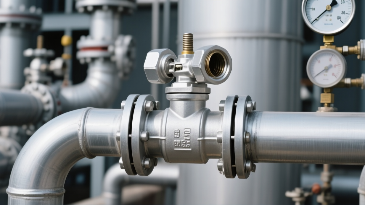
In API 6D trunnion mounted ball valve applications, flanged connections account for approximately 70% of standard pipelines, covering the Class 150 to 900 pressure ranges, and their flange face finish must meet the 125 to 250 microinch (Ra) standard.
Butt Weld (BW) connections are used for zero-leakage long-distance pipelines, and their wall thickness transitions and bevel dimensions must strictly adhere to the ASME B16.25 specification.
A mismatch in end types will lead to an approximate 40% increase in on-site installation man-hours, or generate Volatile Organic Compound (VOC) emissions exceeding 300 ppm per point annually due to improper flange gasket selection.
Flanged Ends
The ASME B16.5 specification defines the flange outer diameter, bolt circle diameter, and flange thickness for NPS 1/2 to NPS 24 trunnion mounted ball valves. When the pipeline size reaches the 26-inch to 60-inch range, the manufacturing standard switches to ASME B16.47 Series A or Series B.
Series A flanges have a large outer diameter and wide bolt hole spacing, suiting long-distance oil and gas pipe networks with higher pipeline stresses. Series B flanges are designed to be lighter and thinner, with a greater number of bolts but smaller diameters, suitable for offshore drilling platforms with constrained installation spaces.
The Raised Face (RF) design handles system pressures from Class 150 to Class 600. Manufacturing requires the sealing face to be machined with concentric or spiral serrations, with roughness maintained between Ra 125 and 250 microinches (3.2 to 6.3 micrometers). The specific roughness allows the metal surface to fully embed into a soft gasket under bolt preload.
The Ring Type Joint (RTJ) design covers high-pressure working conditions from Class 900 to Class 2500. Its sealing face is machined with a trapezoidal ring groove at a 23-degree angle, and the roughness inside the groove is required not to exceed Ra 63 microinches (1.6 micrometers). When high-pressure fluid flows through the pipeline, the internal pressure pushes the metal ring gasket outward against the groove wall.
- Spiral Wound Gasket with Inner and Outer Rings (CGI Type): Adapts to a maximum of 800 degrees Fahrenheit, preventing gasket inward buckling.
- Kammprofile Gasket: Surface covered with a 0.5 mm graphite layer, requires extremely low bolt preload.
- Octagonal Metal Ring Gasket (Type R): Large cross-sectional contact area, requires high finish on the mating groove surface.
- Oval Metal Ring Gasket (Type RX): Pressure-energized sealing design, cross-sectional height is 10% larger than Type R.
- Type BX Metal Ring Gasket: Handles API 6BX flanges, pressure-bearing upper limit reaches 20000 psi.
ASTM A193 B7 alloy steel bolts paired with A194 2H nuts have an application temperature lower limit of -29 degrees Celsius and an upper limit reaching 427 degrees Celsius. Cryogenic processes with ambient temperatures below -29 degrees Celsius adopt L7 grade low-temperature carbon steel bolts.
When handling corrosive high-chloride environments, B8 or B8M (316 stainless steel) bolts possess the capability to resist chloride ion stress corrosion cracking. The yield strength of stainless steel fasteners is only 30% of B7 materials, and thread galling is extremely likely to occur during tightening. Construction personnel need to apply an anti-seize lubricant containing Molybdenum Disulfide (MoS2) prior to installation.
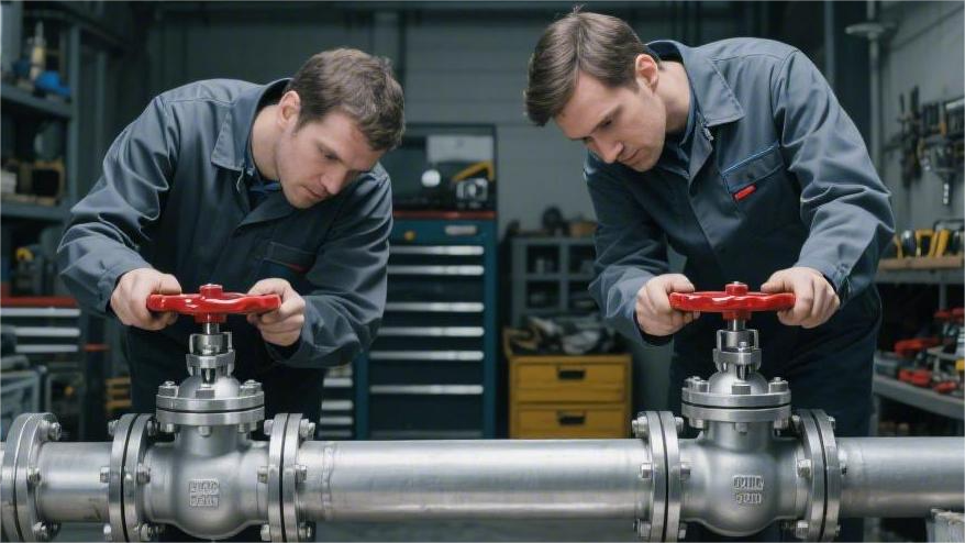
Flange bolt tightening follows a standard crisscross sequence and is completed in three to four torque stages. The initial stage applies 30% of the target torque, the second stage increases to 60%, the third stage reaches 100%, and finally, one full-torque pass is performed in a clockwise direction.
When using a hydraulic torque wrench to handle twenty 1-7/8 inch bolts on a 24-inch, Class 600 flange, a single-side operation takes 1.5 to 2 hours. The flange face parallelism deviation must not exceed 0.03 inches/foot. Exceeding the tolerance will cause insufficient local gasket specific pressure and trigger media leakage.
- Axial spacing error: Maximum allowable deviation is ±1.5 mm.
- Flange hole alignment deviation: Bolt hole center offset does not exceed 3.0 mm.
- Lateral displacement offset: Centerline misalignment must be controlled within 1.5 mm.
- Flange perpendicularity: The angle error between the flange face and the main pipeline axis is less than 0.5 degrees.
Volatile Organic Compound (VOC) emission monitoring is based on the API 624 standard. In ambient temperature and 260 degrees Celsius thermal cycle tests, the leakage measured using methane gas probing at flange static seals is mandatorily restricted to within 100 ppm.
On-site inspectors use a portable Photoionization Detector (PID) for high-precision sniffing along the outer edge of the flange. Once the detection reading exceeds the 500 ppm threshold, it is recorded as a statutory leak event, triggering mandatory initial repair procedures within 5 days according to EPA Method 21 regulations.
Docking flanges of different materials creates a risk of galvanic corrosion. When a duplex stainless steel (ASTM A890 Grade 4A) ball valve is mated with a carbon steel pipe flange, the material potential difference between the two will accelerate the corrosion on the carbon steel pipe side in an aqueous medium.
Flange insulation kits are used to physically block the metal current loop. The kit includes a 0.125-inch thick G10 epoxy glass fiber washer, a full set of insulating sleeves for the bolt holes, and high-strength phenolic resin isolating washers. After installing the insulation kit, the measured resistance value across the two ends of the flange must reach 10 megaohms or more.
- Ultrasonic Thickness Measurement (UT): Measures the wall thickness thinning amount at the flange neck in high flow velocity zones.
- Phased Array Ultrasonic Testing (PAUT): Scans for deep micro-cracks inside high-pressure ring grooves.
- Ultrasonic Bolt Elongation Testing: Verifies the actual residual load after bolt tightening.
- Infrared Thermal Imaging: Troubleshoots temperature anomalies at flange locations covered by insulation layers.
A 36-inch Class 900 trunnion mounted ball valve weighs over 25 tons in total, and the metal thickness of a single-sided flange plate alone reaches 9.5 inches (241 mm). During the design calculation phase, industrial piping systems must add independent high-load-bearing supports beneath their flange necks.
Thermal expansion of the piping system imposes extreme additional physical bending moments on the flange face. When the operating temperature rises by 100 degrees Celsius, carbon steel piping generates a linear extension of 1.2 mm per 100 meters. Stress concentrates at the root of the flange, and exceeding the maximum allowable bending moment limit of the flange will forcefully pry open the flanged sealing face.
Butt Weld (BW)
When the valve body end wall thickness is less than or equal to 22 mm, the specification requires machining a standard V-shaped bevel of 37.5 degrees (tolerance ±2.5 degrees). The Root Face dimension at the bottom of the bevel must be controlled at 1.6 mm, with an allowable deviation of 0.8 mm.
When the end wall thickness of the trunnion mounted ball valve exceeds the 22 mm limit, factories will adopt a compound bevel design. The inner zone maintains a 37.5-degree chamfer angle, while the outer zone’s angle smoothly transitions to 10 degrees. The compound bevel design reduces the total volume of weld metal filled on-site by approximately 20%.
The inner diameter of the valve end must be precisely aligned with the inner diameter of the main pipeline, with the tolerance range restricted between +2.4 mm and -0.8 mm. Misalignment of inner diameters will trigger local turbulence when fluids pass through at high speeds, causing a 24-inch pipeline flowing at 100 feet/second to experience an instant pressure drop increase of 0.5 psi.
- Schedule 40: Standard wall thickness specification; the wall thickness value for a 10-inch pipeline is 9.53 mm.
- Schedule 80: Thickened pipeline standard; a 10-inch pipeline wall thickness reaches 15.09 mm, bearing pressure up to Class 900.
- Schedule 160: Heavy-duty wall thickness; a 10-inch pipeline thickness is 28.58 mm, used in conjunction with Class 1500 systems.
- XXS Series: Double extra-strong pipeline; the wall thickness for an 8-inch size reaches 25.4 mm.
Large-scale on-site welding operations conduct high-density heat to the internal components of the trunnion mounted ball valve. Polytetrafluoroethylene (PTFE) and Polyether Ether Ketone (PEEK) valve seat sealing rings undergo irreversible physical deformation when the ambient temperature exceeds 200 degrees Celsius and 260 degrees Celsius, respectively.
To prevent high temperatures from damaging the seals, factories typically pre-weld a pup piece to the butt weld valve before ex-works. Taking a 16-inch large diameter ball valve as an example, the standard length of the pup pieces equipped on both ends is usually set at 800 mm.
| Valve Nominal Size (NPS) | Minimum Length of Pup Piece (mm) | Maximum Allowable Seat Temperature (°C) |
|---|---|---|
| 2 to 6 | 400 | < 120 |
| 8 to 14 | 600 | < 150 |
| 16 to 24 | 800 | < 180 |
| 26 to 48 | 1200 | < 200 |
The pup piece pushes the Heat-Affected Zone (HAZ) of on-site construction outward. When construction workers complete the butt weld between the pipe and the pup piece, the internal temperature of the valve body remains below the safe threshold, eliminating the cumbersome step of continuously injecting cooling water into the valve cavity.
The Carbon Equivalent (CE) value of the material determines the preheating temperature requirement for welding operations. The CE upper limit for an ASTM A216 WCB carbon steel valve body is set at 0.50; when the actual value exceeds 0.45, the joint must be preheated to 100 degrees Celsius to prevent hydrogen-induced cold cracking during the cooling phase.
API 5L X70 or X80 grade high-strength line pipes have a lower carbon equivalent, averaging around 0.38. When welding a WCB carbon steel valve into an X80 pipeline, welders will use dedicated ER70S-6 welding consumables, relying on the mechanical properties of the consumables to balance the difference in tensile strength between the materials on both sides.
Post-Weld Heat Treatment (PWHT) procedures are used to eliminate the residual stress generated by the cooling of the metal weld pool. The ASME B31.3 standard mandates heat treatment for carbon steel welds with wall thicknesses exceeding 19 mm; the heating band must maintain 595 to 650 degrees Celsius, with a soaking time of 1 hour per inch of wall thickness.
- Gas Tungsten Arc Welding (GTAW): Performs the root pass, uses 100% pure argon shielding gas, possesses extremely high penetration rate.
- Shielded Metal Arc Welding (SMAW): Responsible for the fill and cap layers; E7018 low-hydrogen electrodes are commonly used industry consumables.
- Flux Cored Arc Welding (FCAW): Deposition efficiency reaches 3 to 4 kg per hour, suitable for ultra-thick-walled pipes.
- Submerged Arc Welding (SAW): Factory-level automated process, dedicated for pup piece welding, depositing 10 kg per hour.
Subsea manifold systems entirely utilize butt weld trunnion mounted ball valves. A 12-inch, Class 1500 subsea ball valve installed at a water depth of 3000 meters withstands an external hydrostatic pressure up to 300 Bar.
Over a 20-year design life cycle, the probability of gasket fatigue failure in deep-sea flanged connections is about 15%. Butt welding eliminates all mechanical fastening faces, thoroughly cutting off the physical paths for external seawater ingress and internal high-pressure hydrocarbon leakage.
Non-Destructive Testing (NDT) operations are the last line of defense to verify the quality of on-site welds. The API 1104 standard specifies that all butt welds used in natural gas long-distance pipelines must pass 100% Radiographic Testing (RT) using X-rays or gamma-ray isotopes.
Industrial radiographic films can clearly develop internal porosity and slag inclusion defects as small as 0.5 mm in diameter. When the pipe wall thickness exceeds 25 mm, inspection teams switch to Phased Array Ultrasonic Testing (PAUT) to accurately determine the depth coordinates of lack of fusion defects.
- Incomplete Penetration (IP): Total defect length within a continuous 300 mm weld shall not exceed 25 mm.
- Incomplete Fusion (IF): In any 300 mm inspection segment, the cumulative length upper limit is also 25 mm.
- Internal Concavity: Deemed acceptable as long as the film density on the X-ray radiograph does not exceed that of the adjacent base metal.
- Internal Porosity: Single point diameter shall not be greater than 3 mm, or not exceed 25% of the thinner side’s wall thickness.
The Fully Welded Ball Valve is a derivative category of butt weld connections. The valve shell is assembled by piecing together multiple forged cylindrical segments via single-pass submerged arc welding; there are no connecting flanges fastened by bolts on the valve body.
A 36-inch fully welded ball valve is 20% lighter in overall weight than a three-piece bolted valve of the same specification. Engineers bury it directly in the underground soil and coat the outer surface with a Three-Layer Polyethylene (3LPE) anti-corrosion layer up to 3.0 mm thick.
Maintenance personnel rely on extended pipelines routed above ground to inject grease and maintain the underground valve. A 1/2-inch stainless steel injection line extends vertically upward from the deeply buried seat location, connecting directly to the grease fitting on the ground operation panel.
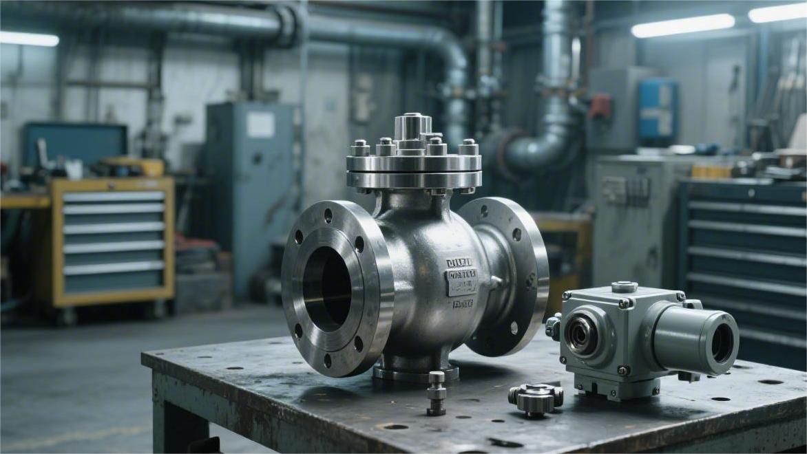
For butt weld pipelines requiring frequent replacement of internal parts, Top-Entry trunnion mounted ball valves offer a disassembly solution. The monolithic cast bonnet of a 24-inch top-entry valve weighs up to 2 tons and is fastened atop the valve body by high-strength bolts.
Maintenance teams, under the conditions of continuous flow and without severing the welds on both sides, use a 5-ton gantry crane and specialized lifting tooling to vertically extract the ball and seat assembly weighing 1.5 tons. The overhead clearance on-site must reserve at least 2.5 meters of lifting operational space.
Hub/Clamp Ends
A high-pressure pipeline connection assembly is formed by assembling two metal ends (Hubs) with 20-degree outer conical profiles, a T-cross-section metal Seal Ring, and a set of split Clamps.
On offshore Floating Production Storage and Offloading (FPSO) units, every physical ton of equipment affects the hull draft and construction costs. A single 12-inch Class 2500 ANSI standard flange weighs up to 850 kg. The total weight of a Hub joint under the same nominal size and pressure rating is only 210 kg, with a physical weight reduction ratio consistently around 75%.
Clamp connections drastically cut down the physical footprint occupied by the outer diameter of high-pressure piping, making compact skid design an engineering reality. Taking a 10-inch Class 1500 pipeline as an example, the outer diameter of a traditional flange is 585 mm, whereas the outer diameter of the correspondingly sized Hub joint is reduced to 320 mm.
On-site construction personnel only need to operate 4 high-strength bolts to complete the assembly and tightening of a set of split clamps. Facing an API 6B high-pressure flange of the same diameter, two workers would need to use hydraulic tools to sequentially tighten 16 heavy-duty alloy bolts of 1-7/8 inch diameter in a diagonal pattern.
Tightening an 8-inch Hub joint using a portable hydraulic torque wrench takes a standard time of about 15 to 20 minutes. The theoretical tightening torque for clamp connections is set in the 300 to 450 Newton-meter range, a value far lower than the extremely high load requirements of large-diameter flange bolts that easily exceed 1500 Newton-meters.
During machining, a minute angular difference of about 1 to 1.5 degrees is reserved between the outer conical surface of the metal seal ring’s rib and the inner bore conical surface of the Hub end. When workers apply bolt preload, the inner cone of the clamp mechanically forces the Hub ends to draw close together.
The metal rib of the seal ring undergoes controlled elastic deformation under physical compression, and its outer surface metal lattice is forcefully fitted against the inner wall surface of the Hub end, forming a high-specific-pressure line-contact static seal.
After the fluid medium enters the trunnion mounted ball valve and piping system, the internal fluid hydrostatic pressure acts on the inner diameter side wall of the metal seal ring. When the system operating pressure climbs from 100 Bar to the high-pressure range of 400 Bar, the medium thrust forces the T-shaped seal ring to expand radially outward.
This mechanism relying completely on metal physical fitting does not use polytetrafluoroethylene polymers, enabling it to withstand conditions ranging from -196 degrees Celsius cryogenic LNG to 760 degrees Celsius refining tail gas. The pressure-bearing surface of the stainless steel seal ring usually undergoes silver plating or Teflon coating treatment, with the coating thickness strictly controlled between 0.01 and 0.02 mm.
The extremely thin surface coating acts as a solid lubricant during metal surface friction, preventing surface galling during the assembly of heavy components. The soft coating can effectively fill in the microscopic machining textures of Ra 1.6 micrometers on the Hub’s inner wall machined surface.
- End Forgings: Commonly used ASTM A694 F60 high-strength steel material, with a lower yield strength limit reaching 415 MPa.
- Clamp Assembly: Mostly manufactured with AISI 4140 alloy steel; after quenching and tempering treatments, surface hardness is maintained in the 22 to 26 HRC range.
- Spherical Washers: Installed beneath the fastening nuts, allowing high-strength bolts to generate a maximum axial deflection of 3 degrees under stress.
The split clamp assembly encapsulates the entire outer thickened step of the Hub end, presenting a 360-degree omnidirectional embracing force-bearing structure in its overall cross-section. When a 16-inch high-pressure pipeline endures intense external physical bending moments, the structural stress is uniformly transmitted to the surroundings through the thick clamp body.
In laboratory tests applying an external ultimate bending moment of 150,000 Newton-meters, the metal mating face of the Hub joint still maintained a zero-leakage and bubble-tight seal state. As a contrast reference, traditional flanges of the same size undergo a single-side microscopic gap opening of 0.2 mm under this physical load.
Dealing with extreme working conditions involving drastic alternating process fluid temperatures, the clamp connection system exhibits a synchronous thermal expansion and contraction rate highly consistent with the main pipe body. When the operating temperature inside the pipe drops or rises sharply from 20 degrees Celsius to 300 degrees Celsius within 1 hour, the tensile deformation of the clamp bolt is only 15% of that of a same-tier flange bolt.
Measured by the maintenance team after 100 repeated disassembly and assembly cycles, the physical wear depth on the conical surface of the Hub end is less than 0.05 mm; the T-cross-section seal ring subjected to compressive deformation is designated as a single-use consumable for independent replacement.
Deepwater manifold production systems heavily utilize Remotely Operated Vehicles (ROVs) to operate clamp-connected valves at a seabed depth of 3000 meters. The ROV’s robotic arm targets and turns a single drive screw outside the clamp, completing the mechanical action of closing or opening within 10 minutes.
The maximum torque output of deep-sea ROV hydraulic motors is normally limited by safety programs to within 2700 Newton-meters. The double-door design of the seabed-specific clamp is equipped with an alloy screw coated with low-friction-coefficient Teflon, effectively reducing the required input torque by over 40%.
Sour oil and gas production wells with high hydrogen sulfide gas content require all pressure-bearing components to mandatorily comply with the NACE MR0175 anti-corrosion standard. The inner bore surface of the Hub end contacting highly corrosive media typically requires automated TIG welding machines to perform a 3 mm thick full cladding overlay of Inconel 625 nickel-based alloy.
- Liquid Penetrant Testing: Verifies whether the outer conical surface of the metal seal ring has fine hairline cracks exceeding 1 mm in length.
- Coordinate Measuring Machine (CMM): Precisely measures the Hub end face inclination angle before ex-works; the angular tolerance is strictly restricted to within ±0.2 degrees.
- Underwater Acoustic Monitoring: Deploys sonar sensors near the clamp nodes of subsea manifolds to capture real-time high-frequency subtle fluid jet noises exceeding 50 kHz.
When two heavy high-pressure pipe segments are mated in mid-air using a crane on-site, the clamp connection mechanism allows a maximum axial misalignment of 1.5 mm during assembly. The spherical mating geometry of the clamp’s inner cavity can physically digest a minute angular offset of up to 0.5 degrees between the metal pipes at both ends.
Failure to thoroughly clean solid sand particles on the inner conical surface of the Hub prior to engineering assembly will cause permanent indentation damage to the sealing surface during the locking phase. Industrial operation specifications mandate the use of non-metallic brushes without loose bristles combined with isopropyl alcohol solvent to control residual particulate size on the surface to below 50 micrometers.

")