
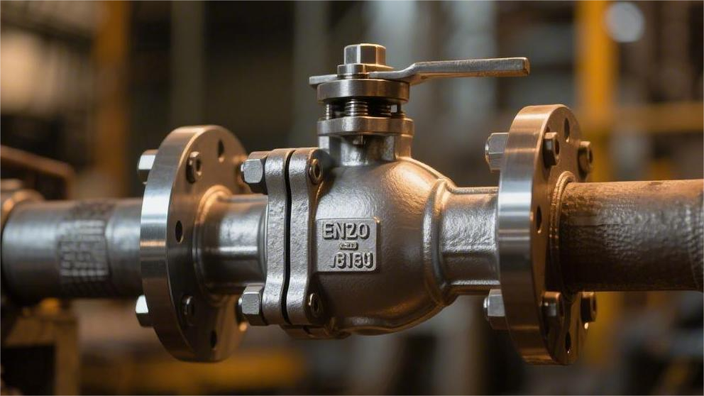
Sizes are customized from NPS 2 to 48; full port structure is mandatory if pigging operations are required;
Pressure ratings strictly adapt from Class 150 to 2500;
Applications with sour media must specify sulfur-resistant materials compliant with the NACE MR0175 standard.
During factory acceptance, a hydrostatic test at 1.5 times the design pressure must be executed to verify safety.
Size
Conventional nominal pipe sizes (NPS) cover 2 to 60 inches.
Selection requires distinguishing between Full Port and Reduced Port: the internal diameter of a full port matches the connected pipeline, with a pressure drop approaching 0 psi, allowing a Pig to pass through;
A reduced port is typically reduced by 1 to 2 NPS sizes, reducing overall weight by 15% to 25%, suitable for non-pigging pipelines where a lower Cv value is acceptable.
Pipe Diameter & Interfaces
For sizes NPS 14 and above, the value equals the actual outside diameter (OD) of the pipe. For example, the OD of an NPS 16 pipe is fixed at 16.000 inches (406.4 mm). For sizes NPS 12 and below, the OD is larger than the nominal value; the OD of NPS 2 is actually 2.375 inches (60.3 mm).
Pipe wall thickness schedules change the internal diameter, requiring the flow path of a trunnion-mounted ball valve to adapt synchronously. The wall thickness of an NPS 8 pipe under Sch 40 is 0.322 inches, with an internal diameter of 7.981 inches; when the operating pressure increases and Sch 160 is adopted, the wall thickness increases to 0.906 inches. At this time, the internal diameter shrinks to 6.813 inches. If a full port ball valve machined to Sch 40 is used, a 1.168-inch physical step will be created at the interface, causing fluid turbulence.
The physical parameters of flange interfaces are divided into two size span intervals. Flange facings for NPS 2 to NPS 24 uniformly follow the ASME B16.5 specification. Taking an NPS 10 Class 300 flange as an example, its OD is 17.5 inches, thickness is 1.88 inches, with 16 evenly distributed bolt holes of 1.12 inches in diameter. The matching bolt circle (BC) diameter is fixed at 15.25 inches.
Large-diameter valve flanges from NPS 26 to NPS 60 must switch to the ASME B16.47 specification. This specification is divided into Series A (derived from MSS SP-44) and Series B (derived from API 605). For NPS 36 Class 600, the Series A flange OD is 50.25 inches, requiring 28 bolts of 1.62 inches; the Series B flange OD is 47.75 inches, utilizing 32 bolts of 1.38 inches.
Regarding the choice between Series A and Series B for large-diameter flanges, three parameter differences must be verified:
- Flange thickness and dead weight: Series A is thicker and heavier, with about 15% higher capacity to bear external pipeline bending moments.
- Bolt distribution density: Series B has more bolts but a smaller individual diameter, resulting in a more uniform tightening force distribution.
- Gasket bearing area: Series A has a wider contact surface, providing over 1.2 times the sealing redundancy against micro-leaks of high-pressure gas.
For Raised Face (RF) flanges in Class 150 and Class 300, the raised height is 0.06 inches (1.6 mm). When the pressure rating rises to Class 400 and above, the raised height is required to increase to 0.25 inches (6.4 mm), coordinating with spiral wound gaskets (CG or CGI type) to achieve physical compression sealing.
To cope with high-pressure environments from Class 900 to Class 2500, flange faces are often machined into Ring Type Joints (RTJ). The hardness of Type R octagonal or oval gaskets must be 15 to 20 HB (Brinell Hardness) lower than the flange groove face hardness. For NPS 12 Class 1500 RTJ flanges, the specification requires the use of R-57 metal ring gaskets; the ring groove depth must be precisely machined to 0.44 inches, and the groove bottom fillet radius is 0.06 inches.
Butt Weld (BW) ends replace flanges in high-temperature, high-pressure pipelines, eliminating 0.1% of potential micro-leakage points. The geometry of the butt weld bevel is specified by ASME B16.25. When the pipe wall thickness (t) is between 0.19 inches and 0.88 inches, the end is machined to a 37.5°±2.5° single V-type bevel. A flat root face of 0.06 inches is retained to prevent the arc from burning through during root pass welding.
When the pipe wall thickness exceeds 0.88 inches (22 mm), the bevel style changes to a Compound Bevel. The lower section of the bevel (within 0.75 inches from the root) maintains a 37.5° angle, while the upper section angle decreases to 10°. The compound bevel design can reduce weld metal fill volume by 20% to 30%, lowering welding residual stress and the probability of intergranular corrosion caused by the heat-affected zone (HAZ).
When assembling butt-welded valves and pipelines, three end measurement data must be verified:
- Material Carbon Equivalent (CE): If the value exceeds 0.43, the area within 150 mm of the ends must be preheated to 200°F to 250°F before welding.
- Transition section machining: When the valve end thickness is more than 1.5 times that of the pipe, a smooth 1:3 taper transition must be machined on the inside or outside.
- Root assembly gap (Root Gap): A physical gap of 0.08 to 0.12 inches is maintained during alignment to ensure a 100% root penetration rate.
The upper limits of the physical dimensions for interface types in actual pipe networks are distributed as follows in the table:
| Interface Type | Standard Specification | Nominal Pipe Size Range | Maximum Pressure Class Adaptation | Fastening/Connection Material Parameters |
|---|---|---|---|---|
| Raised Face Flange (RF) | ASME B16.5 | NPS 2 – NPS 24 | Class 600 | ASTM A193 B7, min. yield 105 ksi |
| Ring Type Joint (RTJ) | ASME B16.47 | NPS 26 – NPS 60 | Class 2500 | 316SS ring gasket, max. hardness 160 HB |
| Butt Weld End (BW) | ASME B16.25 | NPS 2 – NPS 60 | Unlimited | AWS ER70S wire matching pipe material |
“Two-holing” is the alignment guideline for heavy industrial pipeline laying. When the valve is on a horizontal pipeline, the centerline connecting the top two bolt holes on the flange face must be precisely horizontal, and the perpendicularity deviation must not exceed 0.5 degrees. No bolt hole can be located at the absolute top dead center, meaning a Straddle Centerline layout.
The connection interface dimensions between the actuator and the valve stem are governed by the ISO 5211 standard. For an NPS 10 Class 300 trunnion-mounted ball valve, the stem output torque is often around 2500 Nm, requiring an ISO 5211 F16 flange plate. The F16 top flange has an OD of 210 mm, containing 4 M20 threaded holes distributed on a 165 mm pitch circle, and the stem extension length must reach 55 mm to match the scotch yoke actuator connection shaft.
For NPS 2 and smaller vent or drain bypass ball valves, Socket Weld (SW) or NPT threaded interfaces are commonly used. ASME B16.11 specifies the socket depth for SW interfaces; the minimum socket hole depth for an NPS 1 SW valve is 0.50 inches (12.5 mm). After the pipe is inserted, it must be withdrawn outwards by 0.06 inches before fillet welding to reserve physical space for metal thermal expansion.
Internal Bore
Trunnion-mounted ball valves from NPS 2 to NPS 60 are divided into Full Port and Reduced Port flow path configurations.
Manufacturing standards dictate that the diameter of the internal cylindrical passage of a full port ball valve infinitely approaches the connected pipe’s internal diameter. The measured nominal internal diameter of an NPS 16 Sch 40 full port ball valve is 15.000 inches (381.0 mm).
When fluid passes through the 15.000-inch full port passage at a velocity of 5 m/s, the overall pressure drop of the piping system is kept within 0.5 psi.
Pigging operations in crude oil pipelines require the valve to have an unobstructed physical passage. The outside diameter of a polyurethane pig is usually 2% to 5% larger than the pipe’s internal diameter.
When a 15.300-inch pig passes through an NPS 16 full port ball valve, a uniform physical scraping force is generated on the inner wall of the flow path. The internal surface finish (Ra) must reach 1.6 μm to prevent wear and shedding of the pig’s polymer material.
- API 6D specifies that the minimum circular cross-sectional diameter for an NPS 8 full port is 7.94 inches (201.7 mm).
- Gas flow velocity in a full port is limited to below 20 m/s (65 ft/s) to reduce fluid-induced vibration frequencies.
- The misalignment tolerance between the Seat Ring internal diameter and the ball passage edge is controlled within plus or minus 0.03 inches.
- The physical retention rate of solid suspended particles in a straight passage is less than 0.1%.
A conventional Regular Port (single reduced) reduces the internal passage of an NPS 16 valve to the standard NPS 14 internal diameter of 13.124 inches (333.4 mm).
The passage cross-sectional area sharply shrinks from 176.7 square inches to 135.3 square inches. As the fluid passes through the reduced port area, the localized flow velocity instantly increases by about 30.5% within 0.2 seconds.
The sudden change in flow velocity creates a localized turbulence zone within a distance of 1.5 times the pipe diameter downstream of the valve. A design reducing from NPS 16 to NPS 14 will form a 9.5-degree physical reduction angle at the flange ends on both sides.
A Double Reduced port further compresses the internal passage of an NPS 16 to the 11.938 inches (303.2 mm) of an NPS 12. The weight is reduced by 22% to 28% compared to the full port version.
- The ball weight of an NPS 24 reduced to NPS 20 ball valve drops from 3200 pounds to 2100 pounds.
- The stem Breakaway Torque drops synchronously by 35.2%.
- The physical jamming phenomenon renders the reduced port flow path unusable for launching or receiving Smart Pigs.
- When the inlet pressure of the natural gas distribution network is 400 psi, the pressure drop of a single reduction remains around 3.2 psi.
| Nominal Pipe Size (NPS) | Port Type Setting | Measured Internal Bore (Inches) | Test Water Flow Cv Value Quantified | Estimated End-to-End Physical Pressure Drop (psi) |
|---|---|---|---|---|
| 12″ (Sch 40 Pipe) | Full Port | 11.938″ | 11,500 | 0.45 |
| 12″ (Sch 40 Pipe) | Single Reduced (to 10″) | 10.020″ | 6,800 | 2.15 |
| 16″ (Sch 40 Pipe) | Full Port | 15.000″ | 22,100 | 0.38 |
| 16″ (Sch 40 Pipe) | Single Reduced (to 14″) | 13.124″ | 14,200 | 1.85 |
The test fluid uses 60°F standard water, measuring the number of gallons passing through per minute when the pressure drop across both ends is 1 psi.
The measured Cv value of an NPS 12 full port trunnion-mounted ball valve in the 100% fully open state is 11500. Under the same input conditions, the measured Cv value of an NPS 12 reduced to NPS 10 ball valve plummets to 6800.
A Cv value attenuation of up to 40.8% requires the upstream booster pump station to consume extra energy. When an API 610 centrifugal pump deals with the 2.15 psi additional pressure drop brought by an NPS 12 reduced port valve, the shaft power consumption increases by approximately 15.5 kW.
When fracturing fluid containing a high concentration of quartz sand flows through a single reduction angle, the fluid sand-carrying capacity exceeds 3.5 pounds/gallon. Hard particles continuously impact the 9.5-degree reduction angle end at a speed of 15.5 m/s.
Continuous physical impact causes 0.08-inch deep Erosion Pitting to appear on the carbon steel inner wall within a 400-hour operating cycle. The passage size selection must account for the erosion rate.
- The reduction transition zone must use plasma arc welding to overlay 3.5 mm thick Inconel 625 alloy to resist erosion.
- The flow path surface of the full port ball is sprayed with Tungsten Carbide Coating (TCC), with the coating thickness precisely controlled at 0.008 inches.
- After heat treatment, the internal flow path wall of large diameter NPS 36 valves must achieve a minimum machined surface hardness of 400 HV.
- When aerodynamic noise exceeds the 85-decibel limit, high pressure-drop reduced port working conditions must be equipped with a 1.5-inch thick explosion-proof acoustic insulation layer.
Reducing from NPS 20 to an NPS 16 specification drops the physical bearing contact area of the soft seat sealing surface from 115 square inches to 78 square inches.
The substantial reduction in bearing contact area increases the unit physical pressure on the PTFE sealing surface by 1.47 times. Under the Class 900 high pressure-differential (1480 psi) test environment, the single-sided extrusion deformation of a PEEK material soft-sealing seat increases by 0.022 inches.
The alteration of the sealing specific pressure triggers the ball rotation friction coefficient to climb from 0.08 to 0.12. When the actuator outputs the 2000 Nm calibrated torque, the physical wear amount of the reduced port seat is 12.5% higher than that of the full port configuration.
The final physical size selection of the internal port requires inputting into PIPESIM fluid simulation software for a full-pipeline 100-kilometer pressure drop 3D simulation. The operation aims to maintain the Reynolds number (Re) parameter of the fluid within a single pipe segment in a stable turbulence range of 500,000 to 2,000,000.
The API 6D specification requires a 0.5-inch wall thickness Corrosion Allowance to be reserved within the cast cavity of full port valves NPS 4 and above. Because the outer diameter of the reduced port cavity shrinks by 11%, the drilling depth of the bottom Drain Port decreases correspondingly by 1.2 inches.
When the fluid medium is in a Cryogenic condition of minus 196 degrees Celsius, liquefied natural gas occupies a volume of 2650 cubic inches within a 15-inch bore of a full port ball. The instantaneous volume expansion rate caused by the vaporization of trapped liquid is up to 600 times.
Length Adaptation
The overall length of a trunnion-mounted ball valve is strictly controlled by the ASME B16.10 specification. This standard defines the Face-to-Face physical dimensions of Raised Face (RF) flanges. The structural length of an NPS 6 Class 300 flanged ball valve is set at 15.88 inches (403.4 mm).
Manufacturing tolerances set extremely narrow physical boundaries in physical size calibration. The allowable length deviation for sizes NPS 10 and below is plus or minus 0.06 inches (1.6 mm). When the pipe size reaches NPS 12 and above, the allowable tolerance is relaxed to plus or minus 0.12 inches (3.2 mm).
The intervention of Ring Type Joint (RTJ) flanges will change the overall physical length of the valve. The standard length of an NPS 8 Class 600 RF flanged ball valve is 19.75 inches. After replacing with RTJ flanges, metal ring gaskets must be accommodated on both sides, elongating the overall physical length to 19.88 inches.
Butt Weld (BW) valves utilize End-to-End dimension measurements. The end-to-end length of an NPS 24 Class 900 BW ball valve is a staggering 48.00 inches (1219 mm). The butt weld interface requires a 0.12-inch physical root gap to be reserved before welding to achieve full penetration.
During pipeline renovation and expansion projects, issues with old pipelines having non-standard flange spacing are often encountered. The flange face-to-face distance of old NPS 16 pipelines laid in the 1980s might measure 33.50 inches. The current standard length specified by ASME B16.10 is only 33.00 inches.
Manufacturers need to lengthen the casting valve body mold by 0.25 inches on a single side to achieve physical seamless replacement, evading the intergranular corrosion of the Heat-Affected Zone (HAZ) caused by on-site cutting and welding.
Non-standard customized lengths can eliminate the flange residual stress brought about by a 0.50-inch installation gap. Forcibly pulling the pipeline through tightening bolts to close the physical gap will generate a tensile stress exceeding 25,000 psi at the flange root. High-intensity stress in operating conditions containing hydrogen sulfide (H₂S) is highly likely to induce metal sulfide stress cracking.
- Structural length mapping requires a laser rangefinder with an accuracy of 0.001 inches.
- When the Flange Tilt measurement exceeds 0.25 degrees, the flange mating surface must be reground.
- The wall thickness of customized valve bodies must be increased by 12% in the lengthened section to resist additional pipeline bending moment loads.
- High-tensile studs (ASTM A193 B7) must provide 60,000 psi of initial pre-tightening force to counterbalance physical pulling.
- Gasket compression is controlled within a 0.06 to 0.08 inch range to block escaping high-pressure gases.
The length calculation for fully welded ball valves with transition pipe segments (Pup Pieces) is more complex. To prevent on-site welding high temperatures from destroying the internal polytetrafluoroethylene (PTFE) seat sealing rings, X70 steel pipes with a length of 19.68 inches (500 mm) will be pre-welded on both ends before leaving the factory.
The length of an NPS 20 Class 600 fully welded valve body itself is 39.00 inches. After adding a 500 mm transition pipe to each end, the overall physical delivery length reaches 78.37 inches (1990 mm). The intervention of the transition pipes distances the on-site weld seam from the soft sealing seat to an absolutely safe physical range.
The peak metal temperature of the on-site welding area often breaks through 2500°F (1370°C). The physical metal barrier, as long as 19.68 inches, dissipates energy through thermal conduction. The temperature reaching the internal PEEK seat will be forcibly dropped to below 200°F, far below its melting physical deformation critical point of 350°F.
The API 6D specification allows manufacturers and purchasers to custom-negotiate the physical length of Pup Pieces, and the Carbon Equivalent (CE) of the pipe segment material must be controlled below 0.43 to guarantee on-site weldability.
The operation space of the Actuator interferes with the three-dimensional dimensional adaptation. The vertical height from the top of the actuator to the pipeline centerline (Topworks Dimension) is a rigid assessment metric for confined space installation. The vertical height of an NPS 12 ball valve with a pneumatic actuator can reach 55.00 inches.
Valve Stem Extensions are used for adaptation in buried pipelines or cryogenic insulated operating conditions. An LNG receiving terminal’s minus 196°C ultra-low temperature pipeline requires the valve stem to be physically lengthened by 39.37 inches (1000 mm). The extension section is externally wrapped with a 4.00-inch thick Polyisocyanurate (PIR) cold insulation layer to prevent external environmental moisture from icing over.
- The interior of the extended valve stem uses 17-4PH precipitation-hardening stainless steel to transmit a calibrated physical torque of 3000 Nm.
- A Drip Plate is welded 6.00 inches above the bottom of the extension section to physically block condensation water.
- The physical distance from the top ISO 5211 flange to the Stuffing Box is no less than 12.00 inches.
- The wall thickness of the Torque Tube must reach 0.375 inches to resist underground soil settlement extrusion.
The exposed physical temperature of outdoor crude oil pipe networks in North America can reach 140°F (60°C) during summer. An NPS 36 API 5L carbon steel pipeline produces a physical elongation of about 1.85 inches over a 200-foot span.
If the valve face-to-face distance design has no safety margin, an axial thrust of up to 120,000 pounds will force the flanges at both ends of the valve to undergo a minor physical warp of 0.15 degrees.
High-elevation installed valves face a three-dimensional matching calculation of longitudinal structural length and support frame positioning. For an NPS 24 Class 600 ball valve weighing 8500 pounds, its Center of Gravity is annotated 2.15 inches below the valve body’s horizontal centerline.
The length of the support baseplate is usually set at 0.8 times the outer diameter of the ball to disperse the massive dead weight load. The 4 mounting holes with a diameter of 1.12 inches on the baseplate must achieve a physical alignment with a tolerance of less than 0.03 inches with the reserved holes on the H-beam, preventing fastening bolts from being blocked upon insertion.
The length extension of the Drain Line of the valve inner cavity also falls within the scope of three-dimensional space adaptation. The drain pipe of an NPS 2 extends vertically downwards from the bottom of the valve body and must span across an external insulation layer thickness of at least 18.00 inches.
The end of the drain pipe is equipped with a Double Block and Bleed isolation valve, and the total length from the end flange face to the main pipeline centerline can reach 45.00 inches. The long cantilever structure is highly prone to inducing metal fatigue fracture when subjected to fluid physical pulsation frequencies of 60 Hz.
Pressure Class
According to the ASME B16.34 standard, at 38°C (100°F), the maximum allowable pressure for an A105 carbon steel Class 600 valve is 1480 psig, and for Class 1500 it is 3705 psig.
Selection needs to integrate with the API 6D specification, inputting the system’s Maximum Allowable Working Pressure (MAWP) and highest operating temperature, checking against the Pressure-Temperature (P-T) curve.
Before leaving the factory, the valve must pass a shell hydrostatic test at 1.5 times the nominal pressure and a seat high-pressure gas seal test at 1.1 times the nominal pressure in accordance with the API 598 standard.
Interfacing with International Standards
ASME B16.34 classifies valve pressure-bearing materials into different groups; A105 forged steel is grouped into Group 1.1, and F316 stainless steel is grouped into Group 2.2. In a room temperature environment of 38°C, the maximum allowable working pressure of a Group 1.1 Class 1500 trunnion-mounted ball valve is 3705 psig. At the same temperature, the pressure-bearing upper limit of the same class valve made of Group 2.2 material drops to 3600 psig. The difference in material groups requires us to strictly verify the pressure-temperature data sheet when aligning with specifications.
After the shell thickness meets the standard, the connection dimensions at both ends must match ASME B16.5 or B16.47 flange specifications. For trunnion-mounted ball valves of NPS 24 and below, the flange OD and bolt hole pitch conform to ASME B16.5. Large-diameter products from NPS 26 to NPS 60 apply the Series A or Series B dimensional documents of ASME B16.47. The thickness of Series A flanges exceeds Series B by about 15%, making it suitable for 1500 psig environments with higher pipeline stress.
After complying with ASME foundational design parameters, long-distance pipelines require complete adherence to the API 6D 24th Edition pipeline valve specification. API 6D dictates that trunnion-mounted ball valves must complete a shell hydrostatic test lasting 5 minutes before leaving the factory. The test pressure for Class 600 valves is set at 2225 psig, equivalent to 1.5 times the design pressure. The seat high-pressure seal gas test uses 1630 psig nitrogen lasting for 2 minutes, and the leakage must comply with the Rate A zero-leakage level of ISO 5208.
European pipeline projects predominantly follow the EN 1092-1 flange standard and the EN 12516 valve shell wall thickness calculation specification. The PN system calibrates room-temperature allowable pressure in units of bar; the maximum allowable working pressure corresponding to PN 100 is 100 bar. PN 100 valves are similar in size grade to ASME Class 600, but there are millimeter-level minute deviations in flange OD and bolt hole pitch circle diameter.
| Nominal Pipe Size | Pressure Rating System | Flange Outer Diameter (mm) | Number of Bolt Holes | Bolt Hole Diameter (mm) |
|---|---|---|---|---|
| NPS 6 | ASME Class 300 | 317.5 | 12 | 22.4 |
| DN 150 | EN PN 50 | 300.0 | 8 | 26.0 |
| NPS 8 | ASME Class 900 | 469.9 | 12 | 38.1 |
| DN 200 | EN PN 150 | 475.0 | 12 | 33.0 |
API 6A employs a rated working pressure system based on psi, divided into six primary tiers: 2000, 3000, 5000, 10000, 15000, and 20000 psi. API 10000 level trunnion-mounted ball valves strictly mandate the use of 6BX flanges paired with BX ring gaskets. The BX 154 ring groove depth is set at 14.27 mm, and the ring gasket generates a self-tightening seal under the 10000 psi internal fluid squeeze.
Some pipeline networks of Asia-Pacific oil refineries use the Japanese JIS B2220 flange specification. The JIS standard pressure identifiers include 10K, 20K, 30K, 40K, and 63K, where the letter K represents kgf/cm². The maximum allowable working pressure of a JIS 40K trunnion-mounted ball valve at 120°C is 4.0 MPa. The flange thickness for 100A 40K is 36 mm, while the corresponding NPS 4 Class 300 flange thickness is 31.8 mm; the calculation formulas for bolt lengths between the two are different.
| Specification System | Pressure Rating | Shell Hydrostatic Test Standard | Duration (NPS 10) | Seat Pneumatic Test Requirement |
|---|---|---|---|---|
| API 6D | Class 1500 | 1.5 times MAWP (5560 psig) | 5 Minutes | 80 psig Nitrogen |
| API 6A | 10000 psi | 1.5 times Rated Pressure (15000 psi) | 15 Minutes | 10000 psi Nitrogen |
| EN 12266-1 | PN 250 | 1.5 times PN (375 bar) | 3 Minutes | 6 bar Air |
For high hydrogen sulfide content fluids, the pressure-bearing metals must satisfy the NACE MR0175 / ISO 15156 material hardness specifications. The hardness upper limit for carbon steel valve bodies is 22 HRC (237 HBW), and Inconel 625 nickel-based alloy forgings in the annealed state have their highest hardness limited to 35 HRC. Sulfide Stress Cracking (SSC) resistance tests are executed according to NACE TM0177 Scheme A. The specimen must withstand a constant tensile stretch for 720 hours in a 5% sodium chloride and 0.5% glacial acetic acid solution saturated with hydrogen sulfide.
The valve stem stuffing box area must comply with ISO 15848-1 or API 624 fugitive emission micro-leakage specifications. In the API 624 certification test procedure, trunnion-mounted ball valves assembled with graphite packing must complete 310 mechanical cycles and 3 thermal cycles under 260°C methane gas media. The upper limit for methane leakage throughout the entire testing process is 100 ppmv. The ISO 15848-1 Class BH stem sealing structure requires a leakage rate lower than 10^-4 mg/(s·m) under a helium test mass spectrometer.
Flammable and explosive fluid systems mandate that valves pass API 607 or API 6FA fire safety standard certifications. The API 607 7th Edition testing requires the valve to be completely enveloped and burned in flames at 760°C to 980°C for 30 minutes. During the burn, the internal water pressure of a Class 300 valve is maintained at 210 psig. After cooling to below 100°C, the upper limit for total external leakage is 20 ml/(in·min).
P-T Chart
The appendix of the ASME B16.34 standard contains over 80 detailed charts, explicitly defining the pressure-bearing extremes for various metal forgings and castings across different temperature ranges. Taking Group 1.1 A105 carbon steel as an example, within the environmental interval of -29°C to 38°C, the maximum working pressure for a Class 600 trunnion-mounted ball valve is fixed at 1480 psig. Once the temperature crosses the 93°C (200°F) threshold, the yield strength of A105 drops by 12%, and the allowable pressure drops to 1350 psig.
When the pipeline temperature climbs to 426°C (800°F), A105 carbon steel experiences obvious material creep, and the Class 600 pressure-bearing capacity is only 825 psig left. If the temperature continues to rise to 538°C (1000°F), a graphitization reaction occurs within the carbon steel’s internal crystal structure, rendering it no longer suitable for manufacturing any pressure-bearing fluid shell.
For high-temperature gas pipelines above 500°C, the shell material must be replaced with Group 2.2 F316 austenitic stainless steel. A Class 600 valve made of F316 material still retains a 725 psig pressure-bearing margin at 538°C (1000°F). The high-temperature lattice arrangement of F316 austenitic stainless steel is extremely stable, and its carbide precipitation rate is 40% slower than that of ordinary carbon steel.
The pressure-temperature data of the metal shell merely constitutes the external safety boundary; the polymer seats inside the trunnion-mounted ball valve have another independent set of P-T derating curves. The temperature tolerance limit of soft-sealing polymer materials is far lower than that of the outer forged steel shell, and the pressure reduction rate presents a steep exponential drop:
- PTFE (Polytetrafluoroethylene): Working upper limit 200°C, physical pressure bearing is less than 150 psig at 200°C.
- RPTFE (Glass fiber reinforced): Working upper limit 260°C, fused with 15% glass fiber, high-temperature creep resistance increased by 30%.
- Nylon 12: Working upper limit 120°C, possesses excellent low-temperature toughness, suitable for -46°C extremely cold pipelines.
- PEEK (Polyetheretherketone): Working upper limit 260°C, tensile strength can still be maintained at 50 MPa at 200°C.
- Devlon V-API: Working upper limit 150°C, specially developed for high-pressure natural gas, media water absorption is less than 0.1%.
When the gas transmission pipeline media is at 150°C and the pressure reaches 2200 psig, Nylon 12 will experience complete sealing failure due to rapid softening. The high polymer chain distance of Devlon V-API is short and dense, allowing it to maintain a 78 MPa yield stress under a 150°C environment, supporting the massive fluid pressure differential of the Class 900 level without cold flow extrusion occurring.
The fluids at cryogenic LNG (Liquefied Natural Gas) receiving terminals remain at -162°C year-round. According to the API 6D pipeline standard, the risk of brittle fracture for A105 carbon steel surges below -29°C. The system switches to ASTM A350 LF2 or austenitic stainless steel as the main valve body, assembling Kel-F (PCTFE) polymer seats to maintain a mechanical compressive strength of 45 MPa at -196°C.
High-temperature, high-pressure slurry or petrochemical pipelines containing catalyst particles often have internal temperatures breaking through 400°C accompanied by high-speed particle scouring at 15 meters per second. Polymer soft seals will instantly melt or be completely severed under extreme high-wear conditions. The system must completely abandon soft sealing structures and adopt customized Metal-to-Metal Seating schemes:
- HVOF sprayed Tungsten Carbide (TCC): Thickness 0.15-0.2 mm, surface hardness reaching 72 HRC.
- Plasma sprayed Chromium Carbide (CCC): Temperature tolerance limit 850°C, excellent high-temperature hydrogen sulfide corrosion resistance.
- Stellite 6 overlay: Overlay layer 2.0 mm, surface hardness is 38 HRC at 500°C.
- Inconel 625 surface hardening: Resists high-concentration chloride ion stress corrosion cracking, adaptable to high brine working conditions.
In a coal liquefaction pipeline at 450°C and a working pressure of 3500 psig, the surface of a Class 1500 duplex steel F51 ball completes a 0.2 mm thick Tungsten Carbide HVOF spray. Coordinated with Inconel X-750 corrugated springs providing 1200 N of initial mechanical pre-tightening force, the fit degree between the metal seat and the ball surface meets the stringent ANSI/FCI 70-2 Class V leakage rate standard.
While the media temperature changes the material’s yield strength, it also destroys the stress distribution of the bolts at the flange connections. ASME B16.5 specification test data indicates that when the environmental temperature jumps from 38°C to 300°C, the allowable tensile stress of a B7 alloy steel bolt plunges from 25000 psi to 18500 psi. The physical attenuation of the bolt’s mechanical pulling force leads to a synchronous 26% drop in the flange gasket specific pressure.
During system operation, the maximum operating temperature of the trunnion-mounted ball valve must seamlessly stay below the maximum allowable temperature set by the crossover point of the P-T curve. Suppose a crude oil pipeline has a nominal pressure of 1200 psig, and a daily operating temperature of 150°C. An occasional steam purging process noted in the design drawings will generate a 260°C high-temperature shock.
Engineers must use 260°C as the primary design input condition to consult the B16.34 P-T tables. The Class 600 allowable working pressure for A105 material at 260°C is 1175 psig. The 1175 psig threshold is lower than the system’s 1200 psig rated operating pressure. The pipeline design is forced to abandon the Class 600 scheme and select the Class 900 thickened shell to cover the physical derating loss at 260°C.
Manufacturers apply Finite Element Analysis (FEA) in the preliminary design stage to simulate the temperature gradient of the entire valve. After setting the 260°C internal fluid boundary condition, the ANSYS software mesh calculation shows the surface temperature at the top stem stuffing box area drops to 180°C. The volume expansion coefficient of the 3/4-inch cross-section flexible graphite packing at 180°C is measured at 0.05%, sufficient to maintain the 100 ppmv micro-leakage metric required by API 624.
Testing protocols upgrade synchronously alongside pressure-temperature data variations. API 598 requires a gas seal test at 1.1 times the working pressure at room temperature. For PEEK seats assembled under 200°C conditions, the testing standard must be converted to the ISO 5208 appendix specification. The test medium injects 200°C liquid thermal oil, holds pressure for 10 minutes under a 2400 psig pressure differential, and the measured leakage volume for an NPS 8 valve is lower than 2.4 milliliters per minute.
The external seawater temperature of deepwater subsea manifold systems is constant at 4°C year-round. The API 17D specification mandates that subsea valves must withstand the external hydrostatic pressure of extreme 10000 ft depths. For every 33 feet deeper, external seawater pressure increases by 14.7 psi. The continuous static pressure exerted on the outside of the valve body by a 10000-foot deep water column reaches 4454 psi.
The pipeline material chosen is ASTM A890 4A duplex stainless steel. In a 4°C constant temperature seawater environment, the Pitting Resistance Equivalent Number (PREN) of A890 4A is determined to be 35, and the yield strength is 450 MPa. The NPS 12 Class 1500 valve is cast in duplex steel, reducing its overall weight by 18%. The total weight per unit drops to 2150 pounds, substantially cutting down the load-bearing weight for ROV underwater robots during the installation and docking process.
Internal Materials Limits
The external forged steel shell of a trunnion-mounted ball valve can withstand several thousand psi of static fluid pressure, but what truly blocks high-pressure media from leaking inside the system is the extremely fragile internal polymer physicochemical structures and elastic components. When the fluid is shut off, the upstream 2500 psig pressure differential is completely exerted onto polymer sealing rings merely 8 mm thick. Once the mechanical yield strength of the internal material is lower than the fluid shear stress, the polymer will undergo cold flow extrusion from the metal gaps.
In Class 900 high-pressure natural gas pipelines, a physical tolerance gap of 0.15 mm typically exists between the seat metal support ring and the ball surface.
When Rapid Gas Decompression (RGD) occurs inside the pipeline, high-pressure gas permeated inside the elastic O-ring will expand instantaneously. If the decompression rate exceeds 200 psi per minute, the micro-bubbles inside standard FKM (fluoroelastomer) will tear the rubber molecular chains. High-pressure gas gathering and transportation systems mandate that O-rings pass the NORSOK M-710 or ISO 23936-2 Anti-Explosive Decompression (AED) certification testing.
Testing standards stipulate that the O-ring must withstand 15000 psig pressure for up to 72 hours in a mixed gas of 10% hydrogen sulfide and 90% methane. Subsequently, the pressure is exhausted to zero within 15 minutes, and this is cycled 8 times. HNBR (Hydrogenated Nitrile Butadiene Rubber) meeting AED requirements must increase its Shore A hardness to above 90 and increase its cross-link density by 25% to resist the extreme outward expansion pull of internal gases.
The polymer materials of the internal soft sealing seats have extremely strict physical critical points, and engineers must carry out graded replacements based on the absolute value of the media pressure differential:
- PTFE (Polytetrafluoroethylene): Tensile strength 25 MPa; when the pressure differential exceeds 1000 psig, it will generate a 2 mm permanent plastic deformation along a 0.1 mm metal crevice.
- Nylon 12: Tensile strength 50 MPa, can withstand a 2220 psig gas flow impact, and media water absorption is calibrated below 0.15%.
- Devlon V-API: Yield strength 78 MPa; at 150°C and under Class 900 pressure differential, volume expansion rate is strictly controlled within 0.2%.
- PEEK (Polyetheretherketone): Tensile strength 100 MPa; maintains a 3705 psig pressure differential barrier in a 260°C environment, with Shore hardness reaching 85 Shore D.
The corrugated springs or cylindrical springs behind the valve seat support ring providing the initial pre-tightening force are equally restricted by fluid chemical corrosion and mechanical fatigue. Conventional 316 stainless steel springs under a high stress state exceeding 1500 psig will induce stress corrosion cracking upon contact with media containing 50 ppm chloride ions. The system must replace the spring material with Inconel X-750 precipitation-hardening nickel-based alloy.
According to the NACE MR0175 specification, after Inconel X-750 springs undergo 704°C constant temperature aging treatment for 20 hours, the Rockwell hardness upper limit is locked at 50 HRC.
The interlayer structure of graphite carbon atoms will undergo irreversible oxidative burnout in a 450°C oxygen-containing environment. API 622 testing requires 1/4-inch graphite packing to undergo 1510 mechanical lift cycles in 260°C methane, with a weight loss rate not exceeding 5%.
To compensate for the stress relaxation of the graphite packing, Belleville springs will be installed above the packing gland. When an NPS 6 Class 600 valve stem sustains 1480 psig of lateral fluid thrust, two opposingly installed 17-7PH stainless steel Belleville springs can continuously output an axial compensation load of 3500 N. This load can maintain the packing compressive stress at above 1.25 times the fluid pressure.
In fluid systems containing abrasive solid phase particles (such as 5% concentration quartz sand or catalysts), soft-sealing polymers will be cut and peeled off within 48 hours. Engineering specifications mandate the use of full metal sealing structures with metal hardened coatings. Tungsten Carbide (WC-Co) powder impacts the ball surface at a speed of 800 m/s via High-Velocity Oxygen Fuel (HVOF) spraying, forming a 0.2 mm dense coating.
The porosity of the coating is strictly restricted to below 1%, with a bond strength exceeding 70 MPa. Balls and seats with tungsten carbide coatings need to undergo 8 hours of lapping matching on a lapping machine before assembly. According to the ANSI/FCI 70-2 Class VI testing standard, under a 50 psi pressure differential, the allowable air leakage volume per minute for an NPS 4 hard-sealed ball valve is merely 0.15 milliliters.
Extreme chemical media pose sub-tier level compatibility challenges for internal O-ring materials:
- FKM Type A: Fluorine content 66%, temperature resistance 200°C; upon contact with high-concentration methanol or hot steam, the volume expansion rate exceeds 15%.
- FKM Type F: Fluorine content increased to 70%; in a 10% concentration high-pressure hydrochloric acid test, tensile strength retention rate reaches 95% after 72 hours.
- FFKM: Temperature tolerance limit 327°C, can resist over 1600 strongly corrosive chemicals, and the pressure-bearing upper limit of a single sealing ring can reach 25 MPa.
The operating temperature of the Rectisol process (low-temperature methanol wash) is around -60°C year-round; ordinary FKM rubber will lose elasticity and undergo glass transition embrittlement and breakage at -20°C.
Trunnion-mounted ball valves in cryogenic pipelines comprehensively use Lip Seals to replace traditional rubber O-rings. The exterior of a Lip Seal is a U-shaped TFM 1600 modified PTFE jacket, internally embedded with a V-shaped or helical spring made of Elgiloy cobalt-chromium-nickel alloy. In minus 196°C liquid nitrogen media, the Elgiloy spring can continuously provide a radial expansion force of 25 N/mm.
The molecular structure of TFM 1600 is denser than ordinary pure PTFE, and the cold flow deformation amount is substantially reduced by 300%. Under the impact of 2000 psig ultra-low temperature liquid natural gas, the lip of the Lip Seal jacket is pushed towards the metal wall by the fluid, maintaining an extremely low-tolerance rigorous isolation in a minus 196°C environment.
Application
The working conditions directly frame the physical configuration of the trunnion-mounted ball valve. For example, when processing sour natural gas, if the H₂S partial pressure exceeds 0.05 psi, according to the NACE MR0175 specification, the valve inner cavity typically requires an Inconel 625 alloy overlay with a thickness of no less than 3 mm.
For -196°C LNG media, an extended bonnet with a length exceeding 250 mm must be equipped to maintain the packing area above 0°C.
When processing media containing solid particles, a Tungsten Carbide coating with a thickness of 0.2-0.3 mm and a hardness greater than 70 HRC must be formed on the ball surface via the HVOF process. These data are rigid metrics for valve material selection and structural design.
Characteristics & Materials
When the moisture content of the media in the pipeline is below 7 ppm, the uniform corrosion rate of A105 is less than 0.02 millimeters per year. Facing a minus 46°C propane environment, the base material must be replaced with low-temperature carbon steel LF2 or LCC that has undergone Charpy V-notch impact testing, and the impact energy must reach 27 Joules.
Once the fluid is doped with free water and hydrogen sulfide (H₂S), the environment becomes acidic, and the grain boundaries of ordinary carbon steel will be penetrated by hydrogen atoms. The NACE MR0175/ISO 15156 specification explicitly states that when the H₂S partial pressure reaches 0.34 kPa (0.05 psi), the material will suffer Hydrogen-Induced Cracking (HIC) and Sulfide Stress Cracking (SSC).
For different concentrations of sour gas, the hardness and composition requirements of metal materials strictly correspond to specific standards.
| H₂S Partial Pressure | Chloride Ion Concentration | Base Material Selection | Internal Anti-Corrosion Requirements | Rockwell Hardness Upper Limit |
|---|---|---|---|---|
| 0.05 – 1.5 psi | < 50 mg/L | Carbon Steel A105N (Normalized) | Internal coating of Phenolic resin (Thickness 200μm) | 22 HRC |
| 1.5 – 10 psi | 50 – 1000 mg/L | Austenitic F316/F316L | Seat and ball surface plated with ENP (Thickness 75μm) | 22 HRC |
| > 10 psi | > 1000 mg/L | Duplex Steel F51 (2205) / F55 (2507) | Wet flow areas overlaid with Inconel 625 (Thickness 3mm) | 28 HRC |
In offshore oil and gas platform working conditions with a sulfur content exceeding 10%, duplex steel cannot resist pitting. All Wetted Parts surfaces within the valve cavity, including flange faces and seal grooves, undergo overlay welding of a layer of Inconel 625 alloy using the Gas Tungsten Arc Welding (GTAW) process.
The effective thickness of the overlay layer is maintained at over 3.0 millimeters after mechanical machining, and the surface iron element dilution rate is controlled below 5%. If the medium switches to seawater or brine with high concentrations of chloride ions, the passivation film on the surface of austenitic stainless steel will be penetrated by pitting.
For seawater injection systems, the Pitting Resistance Equivalent Number (PREN) becomes the quantified standard for material selection. The PREN value of conventional 316 stainless steel is about 24, while the PREN value of super duplex stainless steel (such as ASTM A890 5A / UNS S32750) exceeds 40, enabling it to remain immune from erosion in seawater with 3.5% salinity.
When handling fluids containing fine sand, catalyst powder, or ore debris, soft sealing seats like PTFE or Nylon will be scratched and fail within 50 switching cycles. The valve interior adopts a Metal-to-Metal hard sealing structure.
Targeting the Mohs hardness of particulate matter, the ball and seat surfaces employ different surface hardening processes:
- Electroless Nickel Plating (ENP): Plating thickness 75 microns, hardness 500 HV, suitable for natural gas pipelines with minor impurities.
- High-Velocity Oxygen Fuel (HVOF) Tungsten Carbide: Spray thickness 0.25 to 0.38 millimeters, bonding strength greater than 70 MPa, hardness reaching 72 HRC, outstanding effect against sediment wear.
- Plasma Transferred Arc (PTA) Stellite 6: Overlay thickness 1.5 to 2.0 millimeters, hardness 40-45 HRC, maintains galling resistance in high-temperature conditions above 400°C accompanied by particulate matter.
Metal hard sealing balls and seats undergo paired lapping on a lapping machine before assembly, ensuring the contact band width reaches 3 to 5 millimeters. Tested according to API 598 or FCI 70-2 standards, its leakage class achieves Class V, allowing a leakage of 0.0005 milliliters of water per minute per inch of nominal pipe size.
Encountering high-concentration industrial acid fluids, such as 98% concentrated sulfuric acid or boiling hydrochloric acid, metal hardened coatings will likewise be dissolved. At this point, depending on the acid’s molarity and operating temperature, corrosion-resistant nickel-based alloy systems are introduced.
Corrosion curves of specific chemicals require precise mapping to specific alloy grades.
| Chemical Medium | Concentration and State | Applicable Valve Body/Trim Material | Material Selection Basis and Data Support |
|---|---|---|---|
| Sulfuric Acid (H₂SO₄) | Concentration < 85%, Room Temp | Alloy 20 (Carpenter 20) | Contains 32-38% nickel and 2-3% molybdenum, annual corrosion rate < 0.1mm |
| Hydrochloric Acid (HCl) | Any concentration, Temp < 50°C | Hastelloy C-276 / C-22 | Molybdenum content up to 15-17%, extremely high tolerance to reducing acids |
| Hydrofluoric Acid (HF) | Concentration < 70%, Oxygen-free env. | Monel 400 (UNS N04400) | Nickel-copper alloy, corrosion rate approaches zero in HF alkylation units |
The molecules of pure hydrogen (H₂) are extremely small, easily penetrating the metal lattice and causing hydrogen embrittlement, or escaping from minute sealing gaps. In high-pressure hydrogen pipe networks, when the working pressure reaches 700 bar (10,000 psi), valve body castings face shrinkage porosity defect risks and must 100% undergo Radiographic Testing (RT) to reach the ASME B16.34 Level 2 standard, or switch to forgings (such as ASTM A105 / F316).
The valve stem stuffing box dimensions of hydrogen valves need to be deepened to accommodate 5 to 7 rings of Chevron PTFE or low-fugitive flexible graphite rings. Tested with a helium mass spectrometer leak detector according to the ISO 15848-1 standard, the leakage rate after 100,000 switching cycles at ambient temperature does not exceed 1.0 × 10⁻⁴ mg/(s·m).
Industrial pure oxygen (O₂) at high flow velocities encountering rust particle friction or grease residue inside pipelines will instantly trigger combustion or even explosions. All trunnion-mounted ball valve components for oxygen working conditions undergo degreasing treatment in an ISO Class 7 cleanroom before assembly.
Temperature Interval Adjustments
When the fluid temperature drops below minus 46°C (such as liquid propane), standard A105 carbon steel undergoes a ductile-to-brittle transition. The material’s Charpy V-notch impact energy will drastically break below the bottom line of 15 Joules.
Pressure-bearing shell materials are strictly required to switch to austenitic stainless steels like ASTM A182 F316 or F304L. In minus 196°C liquefied natural gas working conditions, a 12-inch ball valve body shrinks by up to 2.5 millimeters.
- Follow BS 6364 cryogenic testing specifications
- The lower limit for extended bonnet length is 250 millimeters
- Equipped with a drip plate to block condensation water from icing
- Adopts PCTFE (Kel-F) material for cryogenic soft seals
- Helium mass spectrometer leak detection is performed in a minus 196°C environment
The extended bonnet constructs an insulating gas column between the stuffing box and the cryogenic fluid. The design aims to maintain the temperature of the valve stem packing area above 0°C, preventing flexible graphite or PTFE V-rings from undergoing glass transition freezing and thereby losing elasticity.
The cryogenic liquid trapped in the valve middle cavity will experience violent volume expansion as the environmental temperature rebounds. When liquid nitrogen at minus 196°C absorbs heat, vaporizes, and reaches 20°C, its volume will expand by nearly 700 times.
Engineers will drill a 3 to 5-millimeter pressure relief hole on the upstream side of the ball. When the cavity pressure surpasses 1.33 times the design pressure, the overload pressure automatically vents back to the high-pressure side pipeline along the relief hole.
In high-temperature working conditions above 260°C, the physical structure of polymer sealing materials begins to collapse. PEEK (Polyetheretherketone) possesses a certain degree of temperature tolerance, but its mechanical yield strength will suffer a cliff-like drop beyond 250°C.
The internal structure is comprehensively modified to metal-to-metal sealing. 316 stainless steel balls must calculate a thermal expansion gap; at 400°C, the diameter expansion of a 10-inch ball is roughly 1.8 millimeters, requiring an assembly tolerance of 0.15 to 0.3 millimeters to be reserved during assembly.
- Valve body is upgraded to A182 F22 or F91 chrome-moly alloy steel
- Inconel X-750 Belleville springs are equipped behind the valve seat
- Packing utilizes an alternating combination of molded flexible graphite rings and braided graphite
- The surfaces of the ball and seat undergo HVOF Tungsten Carbide supersonic spraying treatment
The spring behind the valve seat is responsible for continuously pushing the metal seat towards the ball surface. Conventional 316 stainless steel springs will undergo annealing at 300°C, causing the mechanical pre-tightening force to decay drastically.
The internal spring assemblies are replaced with high-temperature alloy materials like Inconel 718 or Nimonic 90, which can maintain a stable spring stiffness of 500 N/mm at 500°C. Lacking the lubrication of soft-sealing polymers, the friction coefficient of metal surfaces climbs sharply.
For an ASME Class 600 8-inch ball valve, its operating torque will surge from 1500 Newton-meters at room temperature to 2800 Newton-meters at 450°C. The selection of pneumatic or electric actuators must introduce a safety factor of over 1.5 times.
The thermal elongation of the valve stem cannot be ignored either. A 500-millimeter long valve stem will generate an axial elongation of 3.5 millimeters at 450°C. The connection sleeve of the drive device must employ a splined or slotted design, reserving an axial play of at least 5 millimeters in the vertical direction.
To prevent heat from conducting along the valve stem to the pneumatic actuator and destroying the Nitrile Butadiene Rubber (NBR) O-rings, an extended bonnet with cooling fins must be installed. A 150-millimeter long isolation section with fins can drop the 400°C conducted temperature to below 80°C before reaching the bottom of the cylinder.
The valves in a molecular sieve dehydration unit must undergo a temperature alternation between 15°C and 320°C every 8 hours. Extreme hot and cold cycling will subject the interior of the materials to severe alternating thermal stress shock.
- The thermal expansion coefficients of the base material and the surface hardened coating must be highly matched
- Valve stem packing adopts a live-loaded pre-tightening structure loaded by Belleville springs
- Overall thermal stress distribution is simulated through Finite Element Analysis (FEA)
- High-temperature cycling testing with pressurized nitrogen is performed per the API 598 standard
An excessive difference in the thermal expansion rate between the coating and the base material will cause the coating to peel off extensively. Using a Tungsten Carbide coating with a cobalt binder, its thermal expansion coefficient is 5.5 µm/(m·K), which is extremely close to the physical parameters of the 410 martensitic stainless steel base material, preventing the coating from cracking during cold and hot alternations.

")