
First verify the operating pressure rating (such as PN16) and the flange standard (ASME B16.5) to ensure the bolt spacing matches exactly.
Then select the body material based on the medium: WCB carbon steel for standard water and gas service, and 316L stainless steel for corrosive fluids.
Before installation, use calipers to measure the outside diameter.
Pressure Rating
In industrial piping systems, the pressure class defines the upper limit of internal static pressure that the valve body and sealing components can withstand. Under ASME B16.34, the pressure capacity of the same material can vary significantly at different temperatures.
At ambient temperature (38°C), the maximum allowable working pressure of an ASTM A216 WCB Class 150 flanged ball valve is 285 psi, while a Class 300 version is rated for 740 psi.
Selection calculations should include the normal working pressure plus a 10% to 15% safety margin to prevent momentary overpressure from water hammer from damaging the body or forcing out the PTFE seals.
International Standard Parameters
ASME B16.5 divides flange materials into 34 groups. ASTM A105 forged steel falls under Group 1.1 and is rated for 260 psi at 200°F. ASTM A182 F316L stainless steel belongs to Group 2.2, where the pressure limit at the same temperature drops to 195 psi.
These pressure limits are tied directly to flange geometry. Standard tables show that flange thickness rises sharply with pressure class. A 2-inch Class 150 flange is 0.62 in (15.7 mm) thick. Upgrading to Class 300 increases the thickness of the same size flange to 0.88 in (22.4 mm).
As thickness increases, the bolt-hole design is also tightly defined. A 2-inch Class 150 flange has four 0.75-inch bolt holes arranged on a 4.75-inch bolt circle and uses 5/8-inch studs for assembly.
Across the Atlantic, the European system follows a different dimensional logic under EN 1092-1. For a DN50 PN16 flange, the specified outside diameter is 165 mm, the thickness is 18 mm, and the flange uses four M16 bolts.
Under the same European standard, when the pressure class rises to PN40, the DN50 flange keeps the same 165 mm outside diameter. The thickness increases to 20 mm, while the number of bolts remains four and the bolt circle diameter stays at 125 mm.
| Standard System | Nominal Size | Pressure Class | Flange OD | Bolt Circle Diameter | Number of Bolts |
|---|---|---|---|---|---|
| ASME B16.5 | NPS 4 | Class 150 | 9.00 in | 7.50 in | 8 |
| ASME B16.5 | NPS 4 | Class 300 | 10.00 in | 7.88 in | 8 |
| EN 1092-1 | DN100 | PN16 | 220 mm | 180 mm | 8 |
| EN 1092-1 | DN100 | PN40 | 235 mm | 190 mm | 8 |
In oil and gas production, compressor-station piping often follows Chapter 24 of API 6D. Once line pressure reaches Class 600, conventional raised-face flanges can develop micro-leakage, so the standard requires Ring-Type Joint (RTJ) flanges.
Under this standard, a 3-inch Class 600 RTJ flange is machined with a trapezoidal groove 0.25 in (6.35 mm) deep. The bottom radius tolerance is limited to a maximum of 0.06 in. The groove must be fitted with an R-31 octagonal or oval metal ring gasket.
Beyond groove design, ASME also specifies the raised-face height as a fixed value. Class 150 and Class 300 RF flanges have a raised face 0.06 in (1.6 mm) high, and this dimension is included in the total flange thickness.
When the system is upgraded to Class 400 and above, the raised-face height changes. The standard increases the RF height uniformly to 0.25 in (6.4 mm), and this raised portion is not included in the nominal base thickness of the flange.
In Asia, JIS B2220 is commonly seen in chemical plants. A 10K 50A flange (equivalent to 2 inches) has an outside diameter of 155 mm, which is 10 mm smaller than an EN flange at a similar pressure rating.
Under the same Japanese standard, a JIS 20K 50A flange is specified at 16 mm thick, with a bolt circle diameter of 120 mm. The face is drilled with eight 19 mm bolt holes and uses M16 bolts for fastening.
For large-diameter pipelines, standard dimensions are found under ASME B16.47, which includes two separate data sets: Series A and Series B. An NPS 30 Class 150 Series A flange has an outside diameter of 38.75 in and is drilled with twenty-eight 1.38-inch bolt holes.
Under the other branch of the same standard, a Series B flange of the same size has a reduced outside diameter of 34.94 in. The bolt count increases to 36, while the bolt-hole diameter drops to 1.12 in to achieve a more compact piping layout.
Once the main dimensions are set, surface finish affects how well the gasket seats. ASME B16.5 requires the concentric serrated finish on an RF flange sealing face to be between 125 and 250 microinches. Each inch of length must contain 45 to 55 serrations.
Changing gasket materials also changes the surface finish requirement. With spiral-wound metal gaskets (SWG), flange surface roughness may be relaxed to 250 microinches. With solid PTFE sheet gaskets, a 125-microinch finish helps reduce leakage of gas media.
| Sealing Face Type | Applicable Pressure Class | Surface Roughness (Ra) | Minimum Tool Mark Spacing |
|---|---|---|---|
| Raised Face (RF) | Class 150-300 | 125 – 250 µin | 0.012 in |
| Raised Face (RF) | Class 400-2500 | 125 – 250 µin | 0.012 in |
| Ring-Type Joint (RTJ) | Class 600-2500 | 63 µin max | N/A |
For RTJ flanges commonly used in ultra-high-pressure piping, the machining accuracy of the groove sidewall is extremely demanding. The sealing surface roughness must not exceed 63 microinches (1.6 microns). Even fine scratches across the groove radius can destroy the zero-leak seal of the metal ring gasket.
Machining accuracy is also tightly controlled by tolerance limits. EN 1092-1 clearly specifies forging tolerances. For a DN100 PN16 flange, the allowable deviation in flange OD is ±1 mm, while the tolerance on the bolt circle diameter is restricted to within ±0.5 mm.
Beyond overall shape tolerance, the acceptable error in bolt-hole diameter is also tightly controlled. Under EN, the tolerance for an 18 mm hole is only +0.5 mm and -0 mm. If the hole is too small, the bolt will not pass through properly.
Historically, large-diameter flange dimensions were split between MSS SP-44 and API 605 in the 1990s. ASME B16.47 consolidated those parameters: Series A inherited MSS SP-44 dimensions, while Series B retained the lighter API 605 format.
Once the dimensional system and tolerance history are matched, selecting an ASME B16.5 flange also requires checking the mechanical property requirements of the ASTM material.
- The minimum tensile strength of an A105 carbon steel flange at room temperature is specified as 70,000 psi.
- The minimum yield strength of A105 is fixed at 36,000 psi.
- A182 F304 stainless steel retains a 20 psi pressure margin at 1000°F (538°C).
For extreme climates, A350 LF2 low-temperature carbon steel is used for piping operating at -46°C. The standard requires a Charpy V-notch impact test at -46°C, and the average absorbed energy of three standard specimens must not be less than 15 joules.
Temperature & Pressure Capacity
The pressure-temperature rating tables in ASME B16.34 are mandatory for determining valve pressure boundaries. If you simply apply the ambient-temperature pressure rating to a valve in hot steam or hot-oil service, the body and sealing surfaces can easily develop high-pressure leakage.
Take ASTM A216 WCB carbon steel as an example. At 38°C, a Class 150 flanged ball valve is rated for 285 psi internal static pressure. Once the process temperature rises to 200°C, the mechanical strength of the carbon steel changes accordingly.
According to the standard rating tables, the maximum allowable pressure for a WCB body at 200°C is limited to 200 psi. That represents a drop of nearly 30% in pressure capacity.
ASTM A351 CF8M stainless steel, often used in corrosion-resistant pipelines, shows an even greater reduction at elevated temperature. At 38°C, its pressure limit is 275 psi. At 200°C, the CF8M pressure rating drops to 195 psi.
- WCB carbon steel at 200°C: pressure limit reduced to 200 psi
- CF8M stainless steel at 200°C: pressure limit reduced to 195 psi
- A352 LCC low-temperature steel at 200°C: pressure limit reduced to 200 psi
- 2205 duplex steel at 200°C: pressure limit reduced to 225 psi
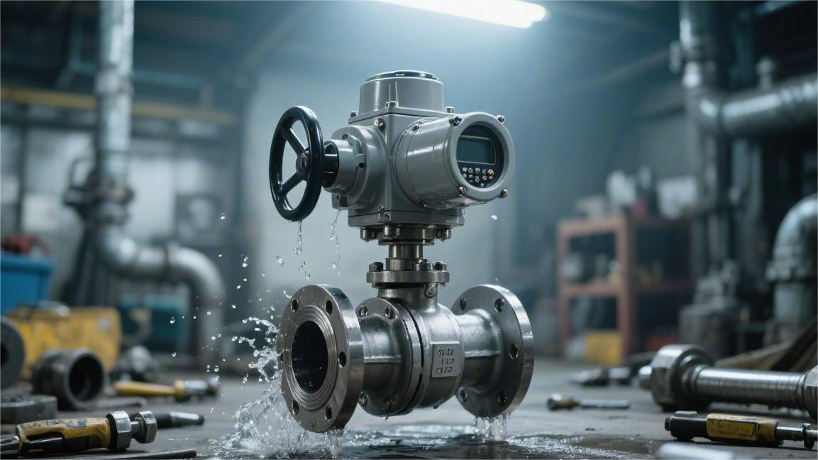
Evaluating the metal valve body is only one part of the selection process. The component that actually blocks the high-pressure fluid inside a flanged ball valve is the polymer soft seat wrapped around the ball. The metal body may still retain its shape at 400°C, but the non-metallic seat may already have softened or failed thermally.
Virgin PTFE is a basic sealing material for pipeline service. Once the operating temperature exceeds 150°C under a media thrust of 100 psi, PTFE undergoes irreversible cold flow. The ball loses proper support, shifts out of position, and high-pressure fluid penetrates the seat clearance.
By blending 15% to 25% glass fiber or carbon fiber into PTFE, manufacturers produce reinforced PTFE (RPTFE). This raises the usable temperature limit to 200°C. At the same test temperature, RPTFE offers about 40% higher compressive strength than virgin PTFE.
In oil and gas water-injection lines operating around 3000 psi static pressure, even glass-filled PTFE cannot resist the physical crushing force of the ball. Under those service conditions, the specification requires switching to PEEK (polyether ether ketone).
PEEK maintains compressive strength above 10,000 psi at 260°C. Its surface hardness approaches that of soft metal, so every opening and closing cycle requires a pneumatic actuator with higher output torque.
For large trunnion-mounted ball valves, API 6D recommends Devlon V-API specialty nylon. This material can withstand thermal conditions up to 190°C and resists the heavy impact of Class 1500 pressure service (about 3705 psi).
- Virgin PTFE: working temperature limit 150°C
- RPTFE (glass-filled): working temperature limit 200°C
- Devlon V-API: working temperature limit 190°C, high impact resistance
- PEEK: working temperature limit 260°C, high hardness
- Metal-seated components: working temperature limit above 500°C
Pressure-temperature derating is the combined physical effect of both the valve body and the sealing components. At high temperatures, the metal body loses strength and the soft seat becomes softer. When reading a P-T curve, both derating effects must be considered together, and the lower of the two values defines the safe operating limit.
Take a Class 300 stainless steel ball valve fitted with RPTFE soft seats and installed in a 200°C pipeline. Under ASME B16.34, the stainless steel body is rated for 430 psi at that temperature. But if the seat supplier’s bench test shows that RPTFE ruptures at 300 psi at 200°C, the valve’s maximum working pressure is effectively capped at 300 psi.
When the actual temperature of a hot thermal-oil line reaches 250°C, all polymer soft-seat systems lose practical engineering value. The sealing faces must be converted to metal seats surfaced with tungsten carbide or Stellite.
When two rough metal surfaces rub against each other, they generate significant mechanical resistance. A 4-inch Class 300 soft-seated ball valve may have an operating torque of 150 N·m. With metal seats installed, the required torque can rise above 400 N·m.
| Seat Sealing Material | Bench Pressure Performance at 200°C | Suitable Pipeline Media | Operating Torque Factor |
|---|---|---|---|
| RPTFE composite | Deforms once pressure exceeds 300 psi | Low-pressure steam, industrial hot water | 1.0 (baseline) |
| PEEK thermoplastic | Withstands 3000 psi without yielding | High-pressure, high-temperature mixed gases | 1.8 |
| Tungsten carbide surfaced seat | Withstands 5000 psi while maintaining zero leakage | Thermal oil above 250°C | 2.5 to 3.0 |
In a boiler room running a 120°C low-pressure steam condensate return system, abnormal conditions are not uncommon. If a pressure-reducing valve fails mechanically, 180°C superheated steam can suddenly flood the line.
Even if the heat spike lasts only five minutes, a virgin PTFE seat selected for a 150°C limit can develop visible charred cracks. When the steam temperature drops back to 120°C, internal leakage has already started.
API 607 fire testing provides the mandatory response to high-temperature disaster scenarios. The ball valve is exposed to open flame at 760°C to 980°C for 30 minutes. The polymer soft seats melt and burn away completely, and the lip on the metal body contacts the metal ball to form a secondary hard seal.
During the fire test, a Class 150 ball valve is subjected to 30 psi internal water pressure. External leakage must remain extremely limited. The packing box is pre-fitted with flexible graphite sealing rings. A standard NBR O-ring would carbonize and crumble completely at 200°C.
- Equipped with flexible graphite anti-leak packing
- Fire-safe lip design with metal secondary sealing surface
- Built-in anti-static spring device to discharge frictional charge
The maximum allowable working pressure (MAWP) marked on the drawing is not the same as the highest measured pressure in the pipeline. Valve selection calculations should add a 15% engineering margin above the peak line pressure.
When flow changes direction at elbows or pumps start and stop suddenly, severe water hammer can develop in the piping system. The resulting pressure spike can reach three to four times the normal static pressure. Without a 15% safety margin, a single water hammer event can tear a polymer seat out of its metal retaining groove.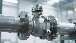
API 598 Factory Testing
API 598 requires every flanged ball valve to go onto a hydrostatic test bench before shipment. Take a carbon steel Class 300 ball valve as an example. Its nameplate shows a room-temperature working pressure of 740 psi. The test pump fills the body with clean water mixed with rust inhibitor and raises the gauge to 1125 psi, which is 1.5 times the valve’s allowable working pressure at ambient temperature.
Hydraulic test clamps lock the blind flanges tightly onto both ends. The filling process removes all free air from the cavity, and the hold timer begins. For a 4-inch ball valve, the shell hydrostatic test must be maintained for 60 seconds. At 10 inches, the mandatory hold time increases to 120 seconds.
When testing an austenitic stainless steel valve made from ASTM A351 CF8M, the water injected into the body must be purified. The chloride content is strictly limited to below 50 ppm, because residual chloride after testing can easily trigger intergranular corrosion.
The inspector uses a strong flashlight to check around the body casting and stem packing area. If even a single droplet appears on the metal surface during the 60-second hold, or if moisture is visible at the edge of the packing box, the entire valve is rejected for rework. The shell test pass criterion is absolute zero leakage.
Once the body passes the 1.5x pressure shell test, the procedure moves to low-pressure seat air testing. After the high-pressure water is drained, an air compressor introduces 60 to 100 psi (4 to 7 bar) of dry air into one side of the closed ball valve. The other side is connected to a transparent cup filled with water so the tester can watch for bubbles.
Compared with hydrostatic pressure in the thousands of psi, this relatively low air pressure is a more demanding test for PTFE soft seats. At low pressure, the ball does not receive enough fluid thrust to force it against the seat. Sealing depends entirely on the assembly preload built into the valve.
For a 2-inch soft-seated flanged ball valve, the low-pressure air test is held for 15 seconds. The tester watches the outlet tube in the water cup closely. Under API 598, if a single bubble appears during the hold period, the seat seal is considered a failure.
| Test Parameter | Low-Pressure Air Tightness Requirement |
|---|---|
| Test medium | Compressed dry air or high-purity nitrogen |
| Line air pressure | 60 psi to 100 psi |
| 2-inch hold time | Mandatory observation for 15 seconds |
| 8-inch hold time | Mandatory observation for 60 seconds |
After the valve passes the low-pressure gas test, the test bench fills the cavity with water again for the high-pressure seat test. This round is conducted at 1.1 times the maximum working pressure at ambient temperature. For the Class 300 carbon steel ball valve above, the high-pressure seat test is set at 814 psi.
High-pressure water enters from one side of the valve and strikes the ball in the closed position. The 814 psi hydrostatic thrust pushes the ball slightly toward the downstream PTFE soft seat. The downstream flange passage is left open, and the inspector checks the unpressurized side for any sign of water droplets.
For a 6-inch pipeline ball valve, the high-pressure seat test hold time is set at 60 seconds. For soft-seated valves, the pass standard remains zero visible leakage. When metal seats with tungsten carbide surfacing are used, the acceptance criteria change.
The mechanical friction of a metal-seated sealing surface allows an extremely small amount of seepage. API defines this tolerance quantitatively. In liquid testing, the allowable leakage is 2 drops per minute per inch of nominal pipe size (2 drops/min/NPS).
For a 4-inch metal-seated ball valve, leakage of 8 drops in one minute is still acceptable. When the test medium is gas, the tolerance is measured in bubbles. The standard allows 24 bubbles per minute per inch of nominal size (24 bubbles/min/NPS).
Trunnion-mounted ball valves in pipeline service are often designed with Double Block and Bleed (DBB), which adds an independent verification step. Water at 1125 psi is introduced from both flange ends separately, and the drain plug at the bottom of the body is manually opened by the inspector.
- Both flange ends are pressurized to 1.1 times the working pressure
- The drain valve at the bottom of the center cavity is opened to check for leakage
- For soft-seated valves, the drain outlet must show zero dripping
This verifies whether the two independent spring-energized seats are physically blocking high-pressure fluid from entering the center cavity. If the PEEK seal ring on either side deforms under pressure, high-pressure water will discharge through the drain port. After the center cavity is drained, a 5-minute hold with no activity at the drain outlet is considered a pass.
Once all pressure tests are complete, the hydraulic fixtures release the flange connections. The assembler then operates the handle or gearbox through three full open-close cycles. On valves fitted with pneumatic actuators, an 80 psi plant air supply is connected to test the response delay of the solenoid valve under a 24V DC signal.
Flange Standard
Flange matching in industrial piping comes down to three hard dimensions: bolt circle diameter (BCD), flange outside diameter, and the number of bolt holes.
Under ASME B16.5, an NPS 2 Class 150 ball valve has a BCD of 120.7 mm with four 5/8-inch holes, while a Class 300 version increases the BCD to 127 mm and changes the hole count to eight.
If a DN50 PN16 valve under DIN EN 1092-1 (BCD 125 mm, four M16 holes) is connected to ASME piping, the bolts will not pass through.
A mismatch in flange standards that creates even a 1 mm spacing deviation can make installation impossible. Forcing the assembly together will load the sealing face unevenly and cause leakage.
Three Major International Flange Parameter Systems
In North American petrochemical plants, ASME B16.5 is the standard reference. On an NPS 8 pipeline drawing, the flange outside diameter for Class 150 is marked as 343 mm. Measure the bolt spacing, and the BCD comes out to 298.5 mm.
The flange has eight evenly spaced 22.2 mm bolt holes and uses 3/4-inch bolts for fastening. Switch to a Class 300 ball valve, and all of the physical parameters change.
On the same NPS 8 pipeline, the flange OD expands to 381 mm, and the thickness increases from 28.6 mm to 41.3 mm. The BCD grows to 330.2 mm, the hole count doubles to 12, and the original 3/4-inch bolts must be replaced with 7/8-inch bolts passing through 25.4 mm holes.
For sizes above NPS 24, ASME B16.47 takes over large-diameter line-pipe dimensions. It splits into two parallel branches: Series A and Series B. Take an NPS 36 Class 600 block valve as an example.
In Series A, the flange OD reaches 1314 mm and the BCD is 1194 mm. Twenty-eight massive 2-1/2-inch bolts are tightened on site with hydraulic tools. Switch to the Series B drawing, and the dimensions change again.
The flange OD for the same size drops to 1226 mm, and the BCD shrinks to 1130 mm. The bolt count increases sharply to 36, while the required bolt size is reduced to 2 inches. If the purchase order omits the A or B suffix, the delivered metal parts will not mate on site.
At higher pressure service, such as Class 1500, a 10-inch steel ball valve flange reaches 108 mm in thickness. The OD extends to 584 mm, and the BCD expands to 483 mm.
This flange, weighing several hundred kilograms, is drilled with twelve 35 mm holes and uses 1-1/4-inch high-strength alloy studs together with a metal octagonal gasket on an RTJ face.
Now shift to a fine chemical plant in Munich, where the drawings use DN instead of NPS. EN 1092-1 governs the piping dimensions, and pressure classes are marked in PN.
Measure a DN150 PN16 carbon steel ball valve, and the flange OD is 285 mm. The BCD measured by caliper is exactly 240 mm. The disc has eight 22 mm holes for M20 metric bolts.
Upgrade the line pressure to PN40, and the flange OD increases to 300 mm. The BCD expands by 10 mm to 250 mm. The number of bolt holes stays at eight, but the hole size increases to 26 mm so workers can apply torque with larger M24 bolts.
In Europe, engineers often also verify the flange back-face type. Type 01 means a plate flange, while Type 11 is a weld neck flange. If the purchase order specifies DN50 PN16 Type 11 but a Type 01 valve is delivered, the welder cannot connect it to a 2.9 mm wall seamless steel pipe.
In the North American system, an NPS 6 Class 150 flange has an OD of 279.4 mm, a BCD of 241.3 mm, and eight 22.2 mm holes.
In the European system, a DN150 PN16 flange has an OD of 285 mm, a BCD of 240 mm, and eight 22 mm holes. The OD differs by 5.6 mm and the BCD by 1.3 mm.
To the naked eye, the two flanges look almost identical, and the bolts may seem to fit. But once the nuts are forced tight, eccentric loading develops and the flange faces tilt slightly. Under 10 bar steam pressure, white high-temperature vapor will blow out through the gap.
| Nominal Pipe Size | Standard / Rating | Flange OD (mm) | BCD (mm) | Number of Bolt Holes | Bolt Hole Diameter (mm) | Flange Thickness (mm) |
|---|---|---|---|---|---|---|
| NPS 4 | ASME Class 150 | 228.6 | 190.5 | 8 | 19.1 | 23.9 |
| DN100 | EN PN16 | 220.0 | 180.0 | 8 | 18.0 | 20.0 |
| 100A | JIS 10K | 210.0 | 175.0 | 8 | 19.0 | 18.0 |
| NPS 4 | ASME Class 300 | 254.0 | 200.0 | 8 | 22.2 | 31.8 |
| DN100 | EN PN40 | 235.0 | 190.0 | 8 | 22.0 | 24.0 |
The third row in the table shows 100A, a designation familiar to workers in Yokohama shipyards under JIS B2220. Dimensions use the suffix “A,” while pressure ratings are marked with numbers ending in “K.”
A 100A 10K marine ball valve has an OD of 210 mm and a BCD of 175 mm. It is visibly smaller than a North American NPS 4 flange, and if you try to fit a North American gasket into it, the edges will stick out noticeably.
If the marine piping is upgraded to 20K, the same 100A flange grows to an OD of 225 mm and a BCD of 185 mm. Thickness increases from 18 mm to 24 mm, the bolt count remains eight, and the hole size expands to 23 mm to accept M20 bolts.
JIS flanges also have a less obvious feature in small sizes. On a 50A drawing, roughly equivalent to NPS 2, a 10K flange has an OD of 155 mm and a BCD of 120 mm.
Four 19 mm holes are spaced evenly around the flange. Move up to 20K, and the 50A flange keeps the exact same 155 mm OD and 120 mm BCD.
The outer geometry stays the same, but the number of holes changes. The 10K version has four holes, while the 20K drawing shows eight. Thickness increases from 16 mm to 18 mm. If the wrong valve is installed using only four bolts, the hydro test will trigger a pressure-drop alarm.
At lower pressure, JIS 5K gives still lighter dimensions. A 150A flange is reduced to 18 mm thickness, with an OD of only 265 mm and a BCD of 230 mm. Compare that with the ASME Class 150 NPS 6 flange used for similarly low-pressure service.
The ASME flange is 25.4 mm thick, and the OD is 279.4 mm—14.4 mm larger. If long bolts are used to pull two flanges of different thickness together, the weaker 5K flange edge will visibly bend inward.
That bending disturbs face flatness, and the non-metallic rubber gasket compressed between the flanges ends up loaded unevenly. One side is crushed paper-thin, while the other side is left with a 2 to 3 mm gap. If the line contains corrosive hydrochloric acid, leakage can reach the plant floor in less than half an hour.
Four Key Measurements
At a refinery in Houston, a pipefitter who receives a ball valve will immediately reach for a vernier caliper. If the drawing specifies ASME B16.5, the first thing to measure is the diameter of the imaginary circle passing through the centers of all bolt holes—what the industry calls the BCD.
Take an NPS 6 pipeline. A Class 150 ball valve has a BCD of 241.3 mm. Switch to Class 300, and the caliper reading has to jump to 269.7 mm. That 28.4 mm difference is enough to make the bolts impossible to insert.
With drawings under EN 1092-1, the whole data set changes. A DN150 PN16 valve has a BCD of 240 mm—only 1.3 mm different from the ASME size above. To the naked eye, that tiny mismatch is almost impossible to detect.
But if workers force-fit that 1.3 mm error by hammering the bolts into place, once 150 psi high-pressure steam is introduced, the two metal flanges will tilt under load. The graphite spiral-wound gasket inside will be squeezed thicker on one side and thinner on the other, and high-temperature fluid will immediately blow out.
When measuring BCD, experienced field technicians follow a standard routine:
- Place the caliper jaws against the inner edges of two opposite bolt holes.
- Read the inside dimension and add the measured diameter of one bolt hole.
- Check the result against the drawing tolerance, usually within ±1.5 mm.
- Mark the measured value on the flange side with an industrial marker.
Once the bolt positions are confirmed, the technician must count exactly how many holes are in the flange. Hole counts are always even numbers. An NPS 2 Class 150 ball valve has four holes, so four sets of nuts and washers are enough.
Raise the pressure requirement to Class 600 while keeping the same NPS 2 size, and the flange is drilled with eight holes. If four bolts are missing, the flange clamping force drops dramatically and the assembly will not survive a 1440 psi hydrostatic test.
Even when the hole count is right, the caliper jaws still need to go inside the holes and measure their diameter. An NPS 8 Class 150 flange has eight evenly spaced 22.2 mm holes. If the order is mistakenly placed for Class 300, the hole count rises to 12 and the hole diameter increases to 25.4 mm.
A valve with 22.2 mm holes is designed for 3/4-inch carbon steel studs. Once the hole size changes to 25.4 mm, workers must retrieve thicker 7/8-inch bolts from the warehouse. If undersized bolts are forced into oversized holes, the valve can shift laterally on a vibrating pipeline.
The large clearance between thin bolts and oversized holes allows the flanges to slip relative to each other under water hammer. The resulting shear force can instantly tear the PTFE gasket clamped in between.
In North American material lists, hole sizes and bolt sizes follow fixed assembly pairings:
- 15.9 mm hole for 1/2-inch bolts
- 19.1 mm hole for 5/8-inch bolts
- 22.2 mm hole for 3/4-inch bolts
- 25.4 mm hole for 7/8-inch bolts
- 28.6 mm hole for 1-inch bolts
Once all bolts are inserted and the nuts are tightened, the last physical limit is the flange outside diameter. It determines how wide the solid metal disc actually is. An NPS 10 Class 150 flange has an OD of 406.4 mm.
Upgrade the drawing to Class 300, and the flange OD expands outward to 444.5 mm. That extra 38.1 mm of metal takes up more operating space. If the piping runs close to a reactor vessel, the larger flange may interfere with the concrete base.
Limited working space creates a chain of problems. If the outer edge of the flange is too close to nearby equipment, the large socket of a pneumatic torque wrench cannot fit over the nut. The fitter is forced to tighten it little by little with a manual wrench.
Manual tightening cannot deliver uniform preload. Compare an ASME flange with a JIS 100A 10K valve: the JIS flange OD is 210 mm, much smaller than the North American NPS 4 equivalent.
Once the flange OD becomes smaller, the thickness usually becomes thinner as well. A JIS 10K 100A flange is only 18 mm thick, while the ASME NPS 4 Class 150 drawing shows a thickness of 23.9 mm.
If two flanges with a thickness difference of 5.9 mm are bolted together and the same torque is applied with a hydraulic wrench, the thinner JIS flange will bend inward at the edge under a load of 300 N·m.
When dealing with large-diameter main pipelines, site conditions place strict limits on flange OD:
- The centerline spacing between adjacent pipelines must leave enough room for flange clearance.
- The concrete trench must be wide enough to accommodate the valve with the largest outside diameter.
- After adding 50 mm of insulation, the assembly must not rub against angle-iron supports.
Only after these four basic geometric dimensions are measured and matched can the flange connection be considered physically acceptable. Even if the pressure designation on the drawing is perfectly clear, a missing bolt hole or a 1 mm offset is enough to make the valve impossible to install into the existing piping system.
Sealing Face Types
At a chemical plant in Texas, workers are replacing an NPS 8 line valve. A pipefitter shines a flashlight onto the old pipeline flange face. Past the eight bolt holes on the outer ring, his eyes stop on a slightly raised metal land at the inner ring. The drawing references ASME B16.5, and the material list is marked with the suffix RF.
To the touch, an RF flange has a circular serrated finish machined by a lathe. Looking up the dimension tables for Class 150 and Class 300, the height of this raised metal face is fixed at 1.6 mm. When the system moves up to Class 600 at the same NPS 8 size, the raised-face height jumps to 6.4 mm.
If a ball valve with a 1.6 mm raised face is forced onto a pipeline flange with a 6.4 mm raised face using a 4.5 mm thick 304 stainless steel spiral-wound gasket, the moment a hydraulic wrench applies 200 N·m of torque, the unequal metal faces will bend the gasket’s outer ring.
When machining an RF face, the lathe leaves serrated grooves. ASME limits this surface finish to 125 to 250 microinches (Ra 3.2-6.3 microns). If the surface is too smooth, the gasket cannot bite into the metal. If it is too rough, the process fluid will leak out along the micro-grooves.
Now move to a low-pressure water-treatment system using ASTM A126 cast iron. At the pump outlet is an NPS 6 Class 125 cast iron ball valve. Its flange face is completely flat from the outer edge to the bore, and the drawing is marked FF.
A flat-face flange requires a full-face PTFE gasket 279 mm in diameter and 3.2 mm thick. The gasket covers the entire flange face, and the bolts pass through matching holes in the gasket. If a carbon steel RF flange with a 1.6 mm raised face is forced against a fully flat FF cast iron flange, the problem starts immediately.
The raised face on the carbon steel flange bears against the center of the flat cast iron flange. As the bolts are tightened around the outer ring, the unsupported edge of the cast iron flange is subjected to severe shear stress. Once the pneumatic wrench output exceeds 300 N·m, the brittle cast iron flange can split from the neck with a sharp crack, leaving a 2 mm wide fracture.
When joining flat-face flanges made from cast iron or bronze, operators follow a separate set of rules:
- The gasket must be a soft EPDM rubber with a Shore A hardness of 60-70.
- Nuts must be tightened in a cross pattern over three stages.
- The first stage is limited to 30% of the design torque, and the second stage rises to 60%.
Now climb onto a North Sea offshore drilling platform, where the natural gas line pressure gauge reads 2160 psi. On the drawings, the flange suffix is no longer RF or FF—it is RTJ. The NPS 4 Class 1500 high-pressure ball valve brought on site has neither a flat face nor a raised face. Instead, the end face contains an 11 mm deep trapezoidal groove.
Insert a vernier caliper into the groove and you will measure a 23-degree side angle. The operator takes an octagonal R39 solid iron ring gasket from the box and places it into the groove.
For high-pressure steam lines above 427°C, rubber and graphite gaskets carbonize. An RTJ face uses the tensile force of high-strength bolts to force a solid iron ring into a 23-degree groove, relying on the plastic deformation of the metal itself to block the high-pressure gas.
The hardness of the pure iron gasket on the purchase order is limited to 120 HB or less, while the flange hardness itself measures 160 HB. The metal ring gasket must be at least 40 HB softer than the flange. If a 316 stainless steel ring gasket with a hardness of 170 HB is forced into place, the part that deforms will be the valve body itself, which may cost tens of thousands of dollars.
At the same NPS 4 size, a Class 900 line uses an R39 ring gasket. Raise the line to Class 1500, and the groove becomes wider, requiring an R44 metal ring with an outside diameter of 162 mm. If an R39 gasket is dropped into an R44 groove, there will be a 3 mm gap all around.
When assembling this kind of trapezoidal ring groove, mechanics carry out several checks:
- The 23-degree groove must be completely free of scratches. Any visible damage deeper than 0.1 mm is rejected immediately.
- A thin layer of molybdenum disulfide anti-seize compound is applied to the contact face of the octagonal ring gasket.
- Twelve 1-1/8-inch B7 alloy bolts are tensioned simultaneously to more than 800 N·m.
Under the European EN 1092-1 system, you will not see RF or FF designations on the drawings. A DN100 PN40 flange face is обозначated as Type B1, with a uniform raised face height of 2 mm. The matching graphite gasket is typically 2.0 mm thick.
Older European drawings may be marked Type A, which corresponds to a flat face. With Type C and Type D tongue-and-groove faces, one flange is machined with a 4.5 mm deep recess and the other with a 4 mm high tongue. The male and female faces fit together, with a 3 mm thick jacketed gasket filling the gap and providing excellent lateral shear resistance.
Valve Material
The material specification for industrial flanged ball valves is divided into three categories: the pressure-bearing body, the internal shutoff components, and the sealing elements.
ASTM A216 WCB carbon steel is suitable for standard service from -29°C to 425°C. CF8M (316 stainless steel), with 2-3% molybdenum, provides resistance to chloride pitting.
For sour natural gas service, metal materials must comply with NACE MR0175 / ISO 15156 requirements for sulfide stress cracking resistance.
Pure PTFE sealing elements can handle a thermodynamic limit of 200°C and a 1000 psi pressure differential. Beyond those temperature and pressure limits, selection must move to PEEK or metal hard seats surfaced with tungsten carbide.
Pressure-Bearing Metal Shell
Choosing the body means choosing both pressure resistance and temperature range. Refineries in Houston, Texas often purchase ball valves in ASTM A216 WCB cast carbon steel in large quantities. WCB can handle standard service conditions from -29°C to 425°C. In chemical plants, buyers watch the carbon equivalent (CE) value closely.
The standard limits CE to no more than 0.43%, and engineers in Texas often tighten their acceptance limit further to 0.38%. If carbon content goes too high, the metal around a full-penetration field weld becomes hard and brittle, leaving invisible cold cracks.
In extremely cold environments, carbon steel needs a different formulation. On natural gas lines in Alberta, Canada, winter temperatures can drop below -45°C. Standard carbon steel becomes brittle there, so field crews specify ASTM A352 LCC low-temperature carbon steel.
When producing LCC steel, the mill must reduce sulfur and phosphorus to below 0.02%. Before shipment, the material must pass a Charpy V-notch impact test. A 10×10×55 mm LCC specimen is struck in a -46°C bath, and if the absorbed energy is below 20 joules, the entire batch is rejected for remelting.
For a more intuitive field reference, here are the basic parameters of four materials commonly used by U.S. engineers:
| Metallurgical Code | Common Name | Yield Strength (MPa) | Applicable Temperature Range | Common Process Media |
|---|---|---|---|---|
| ASTM A216 WCB | Carbon Steel | 250 | -29°C to 425°C | Low-pressure steam, standard oil products |
| ASTM A352 LCC | Low-Temperature Carbon Steel | 275 | -46°C to 340°C | Polar cold-service pipelines |
| ASTM A351 CF8M | 316 Stainless Steel | 205 | -196°C to 537°C | Corrosive chemical process media |
| ASTM A890 4A | 2205 Duplex Steel | 450 | -50°C to 280°C | High-chloride service, seawater |
When handling corrosive fluids, many U.S. chemical plants use ASTM A351 CF8M, or 316 stainless steel, for the valve body. CF8M contains two especially useful alloying elements: 16.0% to 18.0% chromium and 2.0% to 3.0% molybdenum. When exposed to air or water, molybdenum helps form a dense protective film only a few nanometers thick on the metal surface, shielding it from acid and alkali attack.
Conventional stainless steel cannot hold up in highly saline service. On offshore platforms in the Norwegian North Sea, the equipment is constantly exposed to salt-laden sea air. There, engineers typically skip 316 and specify ASTM A890 4A duplex stainless steel.
The Pitting Resistance Equivalent Number (PREN) of 4A duplex steel reaches 34, making it especially effective against chloride attack in seawater. Its ferrite and austenite phases are balanced roughly fifty-fifty, and its yield strength reaches 450 MPa—roughly double that of 316 stainless steel—which gives it excellent pressure resistance.
Whatever metal is selected, the shell itself also has to be thick enough. ASME B16.34 fixes the minimum wall thickness for each pressure class. For a 2-inch Class 300 ball valve, if ultrasonic thickness measurement at its thinnest point shows less than 6.4 mm, that valve must never be installed in the line.
Castings often contain internal shrinkage cavities and porosity that cannot be seen by eye. Before shipment, the entire body must be scanned by X-ray or ultrasonic testing. API 608 is extremely strict: if any blowhole exceeds 10% of the wall thickness in depth or is greater than 1.5 mm, the part is immediately scrapped.
In highly toxic sour-gas service, the shell requirements become especially severe. Deepwater oil and gas in the Gulf of Mexico often contains large amounts of hydrogen sulfide (H2S). Sour gas attacks high-hardness metals first, so all pressure-bearing parts must be qualified to NACE MR0175 / ISO 15156.
Quality inspectors measure the Rockwell hardness (HRC) of each pressure-bearing metal component, and the maximum reading is capped at 22. If the hardness exceeds that level, the valve may develop sulfide stress cracking (SSC) after only a few days in a 15.0 MPa high-pressure line, causing the shell to fail like glass.
Low-temperature gas service is equally demanding. At Ras Laffan Port in Qatar, liquefied natural gas (LNG) is loaded onto tankers at around -162°C. Ordinary metals become brittle at that temperature and can shatter under impact. The piping system relies on ASTM A351 CF8 austenitic stainless steel.
Before assembly, all parts including the body are soaked in liquid nitrogen at -196°C for 8 hours. This cryogenic treatment stabilizes internal structures that would otherwise deform. After assembly, a trace amount of high-pressure helium is introduced into the cavity, and if the external detector records leakage above 1.0×10^-4 mbar·L/s, the entire batch is reworked.
Seat Polymers
Virgin PTFE is the baseline seat material for flow-blocking service in pipelines. Engineering manuals list its friction coefficient at only 0.04. But once internal fluid temperature rises to 150°C under a 1.0 MPa differential pressure, virgin PTFE seats begin to creep visibly.
Ambient-temperature water circulation lines in chemical plants in Louisiana commonly use virgin PTFE. But once those lines are tied into a Class 150 low-pressure steam system, the polymer deforms rapidly under the heat. Manufacturers then blend micro-scale glass fiber into PTFE powder to produce reinforced PTFE (RTFE).
Adding 15% to 25% glass fiber raises the polymer’s compressive strength by about one quarter.
- RTFE with 15% glass fiber: suitable for industrial acids and alkalis at 200°C, with hardness increased to Shore D60.
- PTFE with 25% carbon fill: significantly improved dry-friction wear resistance, suitable for 1.5 MPa steam systems.
- PTFE with 50% stainless steel powder fill: capable of handling the rated differential pressure of Class 300 flanges, with a temperature limit near 220°C.
Ultra-high-pressure gas transmission lines across Alaska face a different kind of mechanical loading. Differential pressure in the line remains at 15.3 MPa (Class 900) to 25.5 MPa (Class 1500). RTFE tears under that gas thrust, so field engineers specify Devlon V-API polyamide for the seats.
The water absorption of Devlon is held below 0.1%. During the rapid depressurization of high-pressure natural gas, gas molecules that have penetrated the seat material expand suddenly. Devlon’s high density withstands this explosive force and passes anti-explosive decompression (AED) testing.
In the high-pressure ethylene cracking units of Texas refineries, operating temperatures approach 250°C. Engineers abandon all PTFE variants and move to PEEK. The crystalline structure of PEEK gives it tensile strength above 100 MPa—four times that of standard Teflon materials.
PEEK has a true melting point of 343°C. Even after long-term immersion in ultra-high-temperature, high-pressure steam at 260°C, dimensional deformation stays below 0.5%. PEEK can also withstand gamma radiation up to 10^9 rads in secondary-loop cooling systems of nuclear power plants.
- Virgin PEEK: handles 260°C and intense nuclear radiation with no harmful outgassing.
- PEEK with 30% carbon fiber fill: hardness approaches Rockwell R125 and is suited to 20.0 MPa high-temperature gas service.
- PTFE-blended PEEK: lowers dry-friction resistance and fits heavy-duty valves with strict operating torque requirements.
In cryogenic LNG service at Ras Laffan Port in Qatar, polymers face the opposite problem: extreme temperature drop. Liquid methane at -162°C flows through the flange cavity, and standard high-temperature plastics become brittle fragments that shatter on contact.
PCTFE maintains excellent compression recovery even in liquid nitrogen at -196°C. A 1-inch-thick PCTFE seat ring can reach a compressive strength of 200 MPa at these subzero temperatures.
A 12-inch Class 600 flanged ball valve fitted with PCTFE seats can achieve zero-bubble leakage on a 10.0 MPa cryogenic test bench. The material’s zero water absorption eliminates the risk of freezing moisture expanding and cracking the seat.
- TFM-1600 modified PTFE: rated down to -100°C and widely used in propane and LPG lines.
- PCTFE: designed for -196°C service and widely used in shutoff valves on LNG loading arms.
- Vespel SP-1 polyimide: usable down to -240°C and suited to aerospace-grade liquid hydrogen fueling lines.
CNC machining of polymer seats follows extremely tight tolerance drawings. The inner spherical sealing surface that contacts the metal ball must be machined to a surface roughness of Ra 0.4 microns. If the finish exceeds that limit even slightly, microscopic plastic burrs can be washed away by high-pressure fluid, leaving a 0.1 mm leakage path.
To compensate for the fatigue limits of a single polymer layer, buyers often add an FKM O-ring behind Devlon or PEEK seats. In 20.0 MPa sour natural gas service, the seat is forced tightly against the ball, while the rubber ring behind it provides an additional 5 mm of mechanical compensation travel.
Third-party laboratories perform NACE TM0297 explosive decompression testing on all types of polymer seats. Seats with rubber back seals are held in a 15 MPa mixed-gas vessel for 72 hours. The operator then evacuates the vessel to vacuum within 15 minutes and inspects the seat cross-section under magnification for bubble cracks larger than 1 mm.
Internal Shutoff Components
ASTM A182 F316 forgings are the most common base material for balls in normal-pressure service. After the CNC lathe machines the forging into a sphere, the external surface roughness is strictly controlled to Ra 0.4 microns or better. If the finish deteriorates to Ra 0.8 microns, just a few hundred cycles in a 1.5 MPa pipeline can gouge visible pits into a soft polymer seat.
If a standard carbon steel ball is placed in a pipeline carrying water and fine sand, rust pits can appear across the surface in just half a month. Field engineers therefore specify ENP (electroless nickel plating) on ASTM A105 forged steel balls. The coating thickness is fixed at 75 microns in the purchase contract.
Inside the plating bath, sodium hypophosphite is reduced at a constant 90°C. A dense nickel-phosphorus alloy layer bonds tightly to the metal substrate, and surface hardness jumps to 500 to 700 HV. That hard shell is enough to resist continuous erosion from 30-micron quartz sand in normal water service.
Oil sands slurry lines in Alberta, Canada are far more severe. The fluid carries large quantities of highly abrasive silica particles at a flow velocity above 5 m/s. ENP coatings cannot survive even one week in this service. Maintenance supervisors there only approve tungsten carbide hardened surfaces on replacement orders.
Valve manufacturers use HVOF equipment to propel micron-scale tungsten carbide particles at around 800 m/s onto the surface of a 316L ball. The coating is typically 0.2 to 0.3 mm thick, with bond strength above 70 MPa and hardness readings above 1200 HV.
- HVOF tungsten carbide: 0.25 mm thick, bond strength above 70 MPa, porosity below 1%, ideal for sand-laden fluids at high velocity and severe wear.
- Plasma-sprayed alumina: a thick ceramic coating resistant to oxidation at ultra-high temperatures, though its thermal shock resistance is weaker and sudden temperature changes above 150°C can crack the surface.
- Laser-clad alloy surfacing: a high-energy laser fuses alloy powder directly into the metal substrate to a depth of 1.5 mm, creating a very strong metallurgical bond suitable for 30.0 MPa high-pressure pulverized-coal gasification lines.
In FCC units in Texas chemical plants, line temperatures often stay around 550°C. High-temperature fluid carrying catalyst particles quickly oxidizes tungsten carbide coatings. In that service, both the shutoff ball and the metal seat are upgraded to Stellite cobalt-based alloy.
Using plasma transferred arc (PTA), welders build up a Stellite 6 layer precisely on the surface of an austenitic stainless steel ball. The alloy contains 28% chromium and 4.5% tungsten, and is usually deposited to a thickness of 1.6 mm. Even at 600°C, its surface hardness remains above 380 HV.
If two unlubricated high-hardness metal surfaces are forced together and rotated under 15.0 MPa line pressure, galling can occur easily. The lattice structure of Stellite provides natural anti-galling properties, preventing the ball from seizing in the hard seat.
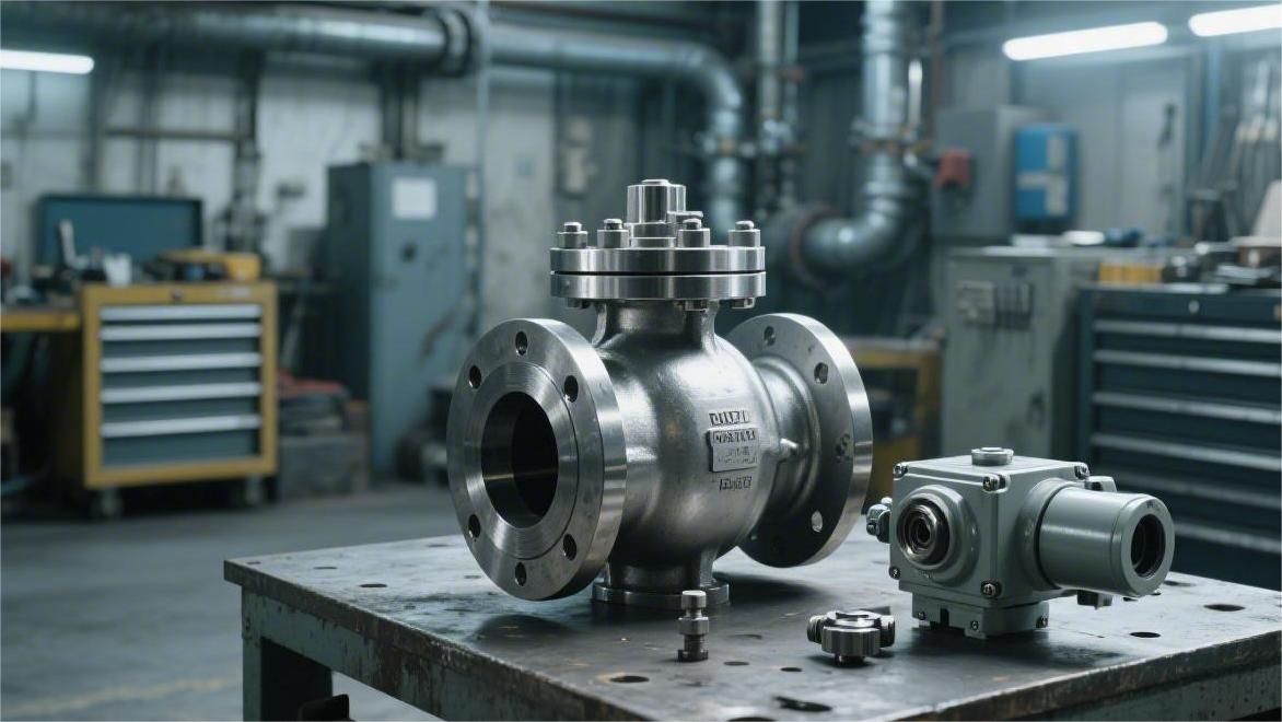
The stem that transmits external torque is subjected to heavy torsional stress. Opening a 10-inch Class 1500 heavy-duty ball valve under full pressure can impose more than 8000 N·m of torque on the metal stem from the pneumatic actuator above.
Conventional 316 stainless steel stems can twist permanently under that kind of extreme pressure. On high-pressure water injection lines in deepwater drilling platforms in the Gulf of Mexico, stem material is upgraded to 17-4PH precipitation-hardening stainless steel. After H1150D double aging heat treatment, its yield strength reaches 725 MPa.
- 17-4PH precipitation-hardening steel: very high tensile strength, suitable for Class 600 to Class 1500 high-pressure systems transmitting very high torque, with excellent resistance to twisting and deformation.
- Inconel 718 nickel alloy: over 50% nickel, highly resistant to H2S corrosion, with yield strength above 1000 MPa, making it standard in deepwater sour oil and gas wells.
- Nitronic 50 stainless steel: nitrogen-strengthened austenitic steel with pitting resistance far beyond 316, and excellent fatigue strength even at -196°C.
At a pressure differential of 20.0 MPa, the gas inside the cavity will try to eject the stem like a bullet. A CNC lathe machines a blow-out-proof shoulder 3 to 5 mm larger in diameter at the bottom of the stem.
During assembly, the worker inserts the stem upward through the body from inside the ball cavity. The higher the internal pressure, the more tightly that metal shoulder is forced upward against the body. Above the shoulder sits a 2 mm thick PTFE or PEEK thrust washer. The shoulder and body clamp the polymer washer tightly between them, blocking the path for high-pressure fluid to leak out along the stem clearance.
Under ISO 15848-1 fugitive emission testing, a suction probe is held directly against the outside of the stem packing box. With 10.0 MPa high-purity helium in the pipeline, the valve is cycled 100,000 times, and leakage is strictly limited to Class B (≤10^-4 mg·s^-1·m^-1).
The blow-out-proof shoulder at the bottom blocks the primary internal pressure, while the V-ring packing in the external stuffing box stops the residual leakage. Under API 607 fire testing, the entire valve is exposed to 760°C flame for 30 minutes. By that point all soft plastics have burned away, leaving only flexible graphite packing outside the stem to seal the gap.
The graphite rings are specified at more than 98% carbon purity, with very low sulfur content to prevent long-term stem corrosion. Maintenance personnel tighten the external gland nuts to 80 N·m with a torque wrench. The multiple graphite layers are compressed by 20% and grip the high-hardness stem, whose surface roughness is only Ra 0.2 microns.

")