
To extend the lifespan of API 6D ball valves, Inconel 625 weld overlay materials should be selected for highly corrosive conditions.
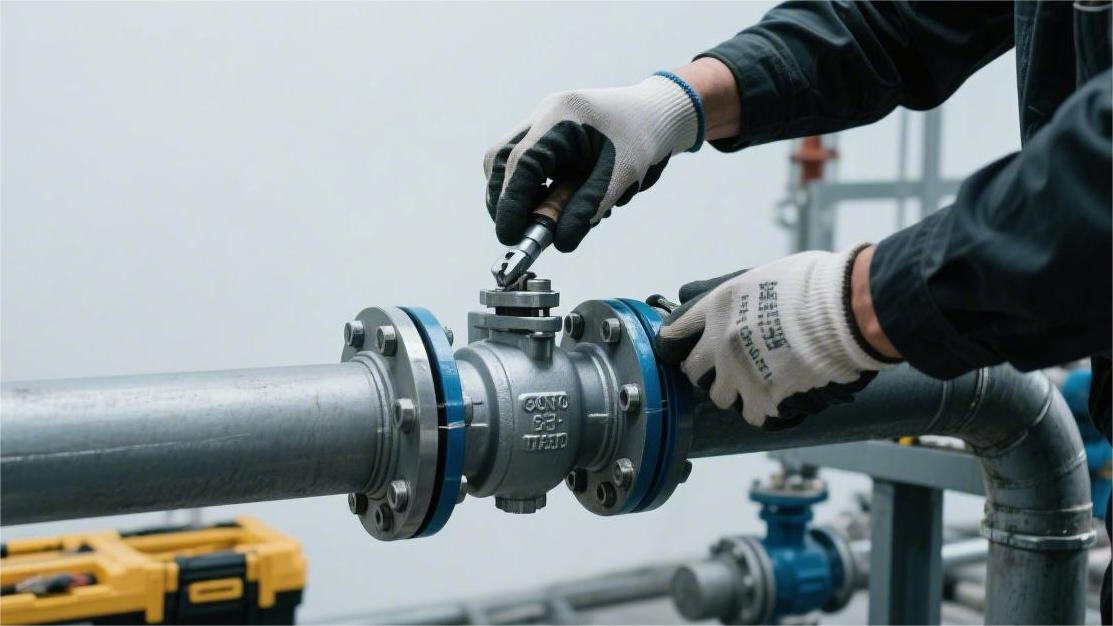
Routine maintenance must strictly execute ultrasonic thickness measurements and grease injection every 6 months.
They must be kept in a fully open or fully closed state; it is strictly prohibited to open them slightly for use as throttling valves, to prevent pipeline fluids from directly scouring and damaging the sealing rings at high speeds exceeding 5 m/s.
Proper Material
Configuring proper materials for API 6D ball valves can extend their service life from 3 years to over 20 years.
The main pressure-bearing metal must match the temperature and media data: standard pipelines use A105/WCB carbon steel (withstanding 285 to 6000 psi pressure), while environments containing H₂S must comply with the NACE MR0175 standard, utilizing duplex stainless steel (PREN value > 35) to prevent cracking.
Internal seals below 150°C predominantly use Devlon or PTFE, switching to PEEK for high temperatures up to 260°C; when facing media containing solid particles, it is mandatory to apply High-Velocity Oxygen Fuel (HVOF) tungsten carbide coating on the ball surface to achieve a metal-to-metal hard seal of HRC 68-72.
Paired with Anti-Explosive Decompression (AED) O-rings, this directly blocks physical wear and chemical corrosion.
Valve Shell
The external pressure-bearing metal wall thickness calculation for API 6D ball valves follows the ASME B16.34 standard. The wall thickness formula considers the nominal fluid pressure and pipe diameter. For 24-inch natural gas pipelines in the Class 600 pressure rating, the minimum valve body wall thickness is specified as 38.1 mm. Engineering designs usually add an extra 3.2 mm corrosion allowance.
To meet the set wall thickness requirements, there are two main forming processes: casting and forging. The forging process heats the metal to 1200°C and applies thousands of tons of mechanical pressure to eliminate internal porosity. The casting process pours molten steel into sand molds, forming complex flow channels upon cooling. For high-pressure pipelines of Class 1500 and above, the API 6D specification mandates the use of forgings like ASTM A105 or A694.
The commonly used cast steel grade for conventional oil and gas pipelines is ASTM A216 WCB, where the Carbon Equivalent (CE) must be controlled below 0.43%. The tensile strength of A105 forged steel ranges from 70,000 to 95,000 psi, with a minimum yield strength of 36,000 psi. Both WCB and A105 grades are suitable for fluid environments from -29°C to 425°C.
| Manufacturing Process | Common Carbon Steel Grade | Yield Strength (psi) | Tensile Strength (psi) | Carbon Equivalent (CE) Limit |
|---|---|---|---|---|
| Sand Casting | ASTM A216 WCB | 36,000 | 70,000 – 95,000 | 0.43% |
| Open-Die/Closed-Die Forging | ASTM A105 | 36,000 | 70,000 – 95,000 | 0.40% |
| Sand Casting | ASTM A352 LCC | 40,000 | 70,000 – 95,000 | 0.45% |
| Open-Die/Closed-Die Forging | ASTM A350 LF2 | 36,000 | 70,000 – 95,000 | 0.42% |
In Canadian oil and gas fields where ambient temperatures fall below -29°C, the Charpy V-notch impact toughness of standard carbon steel drops significantly. Engineers must select low-temperature steels such as ASTM A350 LF2 or ASTM A352 LCC. According to the ASTM A370 standard, low-temperature steel tested at -46°C must have an absorbed energy greater than 27 Joules.
After external metal forming, non-destructive examination (NDE) as specified by ASME BPVC Section V is required. Casting surfaces undergo Magnetic Particle Testing (MT) per ASTM E709, and internal structures are examined using Radiographic Testing (RT). Forgings undergo Penetrant Testing (PT) per ASTM E165 and are scanned with Ultrasonic Testing (UT) for transverse and longitudinal defects. The defect acceptance level is usually set at Level 2.
- Radiographic Testing (RT): According to ASME B16.34 Appendix I, the rating level for porosity and slag inclusions must not exceed Class 2 of ASTM E446.
- Ultrasonic Testing (UT): According to ASTM A388, any defect causing an echo amplitude exceeding the reference hole (3.2 mm flat-bottom hole) will be rejected.
- Magnetic Particle Testing (MT): No linear indications longer than 6.4 mm are permitted on the surface of steel castings.
When transporting fluids with high concentrations of chloride ions on North Sea offshore drilling platforms, carbon steel will experience rapid pitting corrosion. The pressure-bearing shell material must be upgraded to duplex stainless steel (such as ASTM A890 4A or ASTM A182 F51). The F51 material consists of 50% ferrite and 50% austenite, achieving a yield strength of 65,000 psi, and its Pitting Resistance Equivalent Number (PREN) must be greater than 34.
High-sulfur natural gas pipelines contain hydrogen sulfide (H₂S). According to NACE MR0175/ISO 15156 Part 3, metal components are subject to hardness and composition limits in addition to strength metrics. The maximum Rockwell hardness (HRC) limit for the material is set at 22. Post-Weld Heat Treatment (PWHT) must be executed during manufacturing to eliminate internal residual stress.
The flange connection dimensions at both ends of the pressure-bearing metal comply with the ASME B16.5 specification. Class 150 to Class 600 typically use Raised Face (RF) flanges, with a surface roughness requirement between 125 and 250 microinches (Ra). High-pressure conditions of Class 900 and above utilize Ring Type Joint (RTJ) flanges machined with trapezoidal octagonal gasket grooves.
| Pressure Class | Applicable Flange Type | Flange Face Roughness (Ra) | Matching Gasket Type | Pressure Test Multiple |
|---|---|---|---|---|
| Class 150 | Raised Face (RF) | 125 – 250 µin | Spiral Wound Gasket (CG/CGI) | 1.5x Nominal Pressure |
| Class 600 | Raised Face (RF) | 125 – 250 µin | Spiral Wound Gasket (CG/CGI) | 1.5x Nominal Pressure |
| Class 900 | Ring Type Joint (RTJ) | < 63 µin | Octagonal/Oval Metal Ring Gasket | 1.5x Nominal Pressure |
| Class 2500 | Ring Type Joint (RTJ) | < 63 µin | Octagonal Metal Ring Gasket | 1.5x Nominal Pressure |
The shells of three-piece or two-piece pipeline ball valves are secured by bolts and nuts. The bolt material uses ASTM A193 B7 alloy steel, with a minimum tensile strength of 125,000 psi. Nuts use ASTM A194 2H high-carbon steel, with a hardness between HRC 24 and 35. For environments below -46°C, ASTM A320 L7 bolts are substituted to ensure low-temperature toughness.
The assembled valve shell undergoes a hydrostatic shell test in accordance with the API 6D specification. The test fluid is mostly pure water containing rust inhibitors, with a chloride ion content below 50 ppm. It is pressurized to 1.5 times the nominal cold working pressure. For pipeline ball valves over 20 inches, the holding time requires a minimum of 15 minutes, during which no visible leakage is allowed on the shell surface.
Valve Seat Seals
API 6D ball valves internally rely on the tight fit between the seat ring and the ball surface to cut off fluid. Inconel X-750 wave springs are assembled behind the seats to provide initial mechanical preload. The thrust of each spring group is often set between 150 and 300 pounds-force.
When the fluid pressure in the pipeline fluctuates between 150 psi and 6000 psi, the fluid thrust presses the seat against the ball. Clean natural gas pipelines are often equipped with non-metallic soft sealing inserts. PTFE (Polytetrafluoroethylene) has a friction coefficient of only 0.04, resulting in extremely low valve operating torque.
Pure PTFE will suffer cold-flow deformation when the temperature exceeds 120°C or the pressure is higher than Class 600. Factories will blend 15% to 25% glass fiber or carbon fiber into the resin for reinforcement. The pressure limit of RPTFE (Reinforced PTFE) is elevated to Class 900.
Entering ultra-high-pressure natural gas mainlines of Class 1500 to Class 2500, the anti-creep capabilities of RPTFE fall short. Engineering pipelines universally switch to Devlon V-API high-molecular nylon materials. Devlon’s water absorption is controlled below 0.1%, and its pressure limit exceeds 4000 psi.
When fluid temperatures climb above 200°C, Devlon will soften and fail. High-temperature hydrocarbon fluids in refineries must be equipped with PEEK (Polyetheretherketone) seats. PEEK has a glass transition temperature of 143°C and still maintains extremely high mechanical compressive strength at high temperatures of 260°C.
For cryogenic LNG (Liquefied Natural Gas) transportation pipelines below -46°C, standard polymer materials will completely embrittle. Engineering specifications mandate switching to specific cryogenic materials.
- PCTFE (Polychlorotrifluoroethylene): Minimum temperature resistance reaches -196°C.
- Mechanical Strength: Yield strength parameters are required to reach 4,500 psi.
- Tensile Testing: Maintains 5,500 psi under extreme cold testing.
- Dimensional Shrinkage: Machining dimensional tolerances must compensate for a low-temperature cold shrinkage rate of about 2%.
A groove is machined behind the polymer seals, embedded with an elastomeric O-ring to block back-pressure leakage. Fluoroelastomers (FKM / Viton) provide excellent resilience at normal ambient temperatures (-20°C to 200°C). The Shore A hardness is set to 90 to resist high-pressure extrusion.
Sour gas pipelines containing over 5% hydrogen sulfide will corrode standard fluoroelastomers. Oil and gas field operations employ HNBR (Hydrogenated Nitrile Butadiene Rubber) or Aflas (Tetrafluoroethylene Propylene Rubber). The elastomer formulation must pass the NORSOK M-710 Revision 3 standard test.
- Test Gas Mixture: 10% H₂S plus 90% CH₄.
- Upper Ambient Temperature Limit: The test chamber temperature is set up to 150°C.
- Exposure Time Standard: Elastomers must be continuously immersed for 28 days.
- Physical Degradation Redline: The drop in tensile strength must not exceed 50%.
When long-haul pipelines experience Emergency Shutdown (ESD) blowdowns, the pipeline pressure drops abruptly from 1000 psi to atmospheric pressure within minutes. High-pressure gas dissolved inside the O-rings expands rapidly. Standard rubber will undergo Anti-Explosive Decompression (AED) phenomena, developing dense surface cracks and shattering.
Rapid Gas Decompression (RGD) O-rings are manufactured through high-density cross-linking processes. Some ultra-high-pressure or ultra-low-temperature applications completely abandon rubber, opting for U-shaped Lip Seals. The outer jacket is turned from PTFE or Teflon, with an Elgiloy cobalt-nickel alloy spring pre-installed inside.
Associated gas from crude oil often entrains quartz sand, rock cuttings, and metallic weld slag. Solids-laden fluids reaching velocities of 10 meters per second generate intense physical scouring the moment the valve opens. Soft sealing inserts will be gouged with grooves over 1 mm deep within hours.
Metal-to-Metal hard sealing has replaced polymer seats in abrasive media. The seat substrate typically uses ASTM A182 F316L or 17-4PH precipitation-hardening stainless steel. The contact surface is sprayed with a hardened layer 0.15 to 0.2 mm thick.
The spraying process heavily relies on High-Velocity Oxygen Fuel (HVOF) technology. Tungsten Carbide powder impacts the metal surface at a speed of 800 m/s under extreme high temperatures of 2500°C. The Rockwell hardness (HRC) of the coating stabilizes between 68 and 72.
Tungsten carbide coatings undergo severe oxidation in high-temperature steam or catalytic cracking units exceeding 400°C. Engineering specifications mandate replacing the coating material with Chromium Carbide. The oxidation temperature limit of Chromium Carbide reaches up to 815°C.
Hard-sealed seats require a high-precision spherical lapping process. CNC machines, paired with 1200-grit diamond lapping paste, match-lap the ball and seat for over 8 hours. The surface roughness (Ra) is reduced to below 4 microinches (0.1 micrometers).
The leakage rate of the lapped metal mating surfaces complies with the ANSI/FCI 70-2 standard. The Class V standard allows a leakage of 0.0005 ml of water per minute per inch of pipe diameter. Class VI uses nitrogen testing, placing stricter limits on the number and volume of bubbles.
Seat structures for high-pressure pipelines are also divided into Single Piston Effect (SPE) and Double Piston Effect (DPE). When the body cavity pressure exceeds the pipeline pressure by approximately 200 psi, an SPE seat will compress the springs and automatically relieve pressure toward the pipeline side.
Ball Surface Coating
Under the API 6D specification, the sealing performance of pipeline ball valves not only depends on the previously mentioned soft and hard seats, but the surface condition of the internal metal ball mating against them is constrained with equal strictness. For untreated ASTM A105 or A350 LF2 carbon steel balls in natural gas pipelines containing more than 0.5% free water, the outer wall will develop a loose iron oxide (Fe₂O₃) rust layer within 72 hours.
Engineering pipelines mandate that the ball possesses the dual attributes of corrosion resistance and mechanical scratch resistance. Carbon steel or low-alloy steel substrates must have an external protective layer added via electrochemical deposition or high-energy thermal spraying processes, with specific thickness and hardness metrics defined by ASME B16.34 and NACE MR0175 standards.
Electroless Nickel Plating (ENP) is the most widespread foundational surface treatment process in Class 150 to Class 600 conventional pressure rating long-haul pipelines. Processing facilities fully submerge the entire metal ball in a chemical reduction plating bath containing sodium hypophosphite, maintaining a constant bath temperature between 85°C and 92°C.
According to the ASTM B733 testing standard, the ENP coating thickness on the surface of API 6D ball valves is precisely limited to 75 micrometers (0.003 inches), with an allowable upper and lower tolerance of only 5 micrometers. The phosphorus mass fraction in the coating must reach 10% to 14%, causing the crystal structure to present an amorphous state to sever corrosion pathways.
The initial Rockwell hardness (HRC) measurement of high-phosphorus ENP coatings without Post-Weld Heat Treatment is between 48 and 52. By placing the finished nickel-plated ball in a heating furnace at 350°C to 400°C and holding the temperature for 1.5 to 2.0 hours, Ni₃P hardening phases precipitate inside the coating, and the overall hardness climbs to HRC 65 to 68.
- Passing the ASTM B117 neutral salt spray test specification, a 75-micrometer thick high-phosphorus ENP ball can resist over 1000 hours of continuous 5% NaCl salt spray without any red rust spots visible to the naked eye.
- In the pin-on-disk friction and wear test conducted according to ASTM D2714, the ENP surface operates in contact with a polytetrafluoroethylene (PTFE) soft seat, and the relative sliding friction coefficient remains stably between 0.12 and 0.15 over the long term.
- The deposition rate of industrial electroless plating baths is typically 15 to 25 micrometers per hour. Processing a large ball for a 24-inch pipeline ball valve requires continuous immersion and high-speed fluid circulation for about 4 to 5 hours.
In the development of sour gas fields in North America and the Middle East, when the H₂S concentration in the fluid exceeds 500 ppm, a single ENP coating is prone to microporous gas permeation under medium to high pressures. Engineers will first use the TIG process to weld a 3 mm thick Inconel 625 nickel-based alloy overlay onto the surface of the A105 carbon steel ball, followed by precision OD turning.
Facing oil gathering pipelines laden with hard solid particles like quartz sand and iron shavings, abrasive media flowing at speeds up to 15 m/s will instantly scratch through a 75-micrometer ENP coating. For conditions above Class 900, the engineering sector universally pivots to employing High-Velocity Oxygen Fuel (HVOF) technology to adhere hard alloy materials.
HVOF processing equipment burns high-purity kerosene or propane gas, combined with high-pressure oxygen, to generate an ultra-high-temperature jet of 2500°C to 3000°C inside the spray gun’s combustion chamber. Metal powder particles containing a specific ratio of binder are accelerated to 800 to 1000 m/s (about 2.5 to 3 times the speed of sound) to impact the ball’s outer wall.
The immense kinetic energy of the high-speed flying powder translates into massive plastic deformation, as fine particles form dense, flat “pancake” layers overlapping on the ball substrate. The internal porosity of the formed coating is strictly suppressed to below 1%, drastically reducing the probability of fluid penetrating and corroding the underlying substrate.
For severely abrasive pipelines operating below 400°C, 86WC-10Co-4Cr (Tungsten Carbide-Cobalt-Chromium) is the most common powder formulation for HVOF spraying. Here, 86% of the tungsten carbide phase provides extremely high physical wear resistance, 10% cobalt acts as the metallic binder phase, and 4% chromium element enhances external corrosion resistance.
- The nominal thickness after tungsten carbide coating spraying is typically set between 150 and 250 micrometers (0.006 to 0.010 inches); exceeding 250 micrometers easily triggers coating spalling due to internal stress.
- According to the coating tensile test conducted per the ASTM C633 standard, the mechanical bond strength between the tungsten carbide hardened layer and the ball substrate must be greater than 10,000 psi (approximately 70 MPa).
- Measuring the coating cross-section with a microhardness tester, Vickers hardness (HV0.3) readings cluster between 1100 and 1300, equivalent to a Rockwell hardness of HRC 68 to 72.
Immediately after high-velocity tungsten carbide spraying is completed, the outer surface of the ball is extremely rough, with a roughness Ra typically greater than 5 micrometers, and must be transferred to a CNC ball grinder for high-precision polishing. Operators use a resin-bonded diamond grinding wheel at speeds of 300 to 500 RPM to perform dozens of continuous lapping passes on the surface.
The surface roughness of the finely ground ball must be strictly reduced to Ra 0.1 to 0.2 micrometers (4 to 8 microinches). If the pipeline is assembled with metal-to-metal hard seal seats, the surface of the ball and the matching seat must be coated with 800-grit to 1200-grit boron carbide or diamond lapping paste, undergoing gapless match-lapping on dedicated machine tools for 8 to 12 hours.
In Canadian oil sands extraction pipelines or heavy oil catalytic cracking units in refineries, media temperatures frequently break past 500°C, with some vent pipelines even reaching 800°C. Conventional tungsten carbide materials will suffer severe oxidation at high temperatures above 400°C, forming structurally loose tungsten oxide (WO₃), ultimately leading to large-scale peeling and failure of the outer coating.
Pipeline engineers replace high-temperature spray powders with 75Cr₃C₂-25NiCr (Chromium Carbide-Nickel Chromium). Chromium carbide materials maintain a stable physical structure under extreme high-temperature environments of 815°C. Its overall coating hardness is slightly lower than tungsten carbide, with Vickers hardness readings between HV0.3 800 and 900 (roughly equivalent to HRC 60 to 65).
In special pipelines with extremely high temperatures accompanied by strong acidic corrosion, an HVOF coating thickness of less than 0.3 mm cannot provide physical protection for a multi-decade life cycle. Valve manufacturers employ Plasma Transferred Arc (PTA) welding processes to clad Stellite 6 alloy onto the ball’s pressure-bearing surface.
The arc temperature generated by PTA heat source cladding reaches up to 10,000°C, resulting in deep metallurgical bonding between the Stellite 6 alloy powder and the underlying metal substrate. The thickness of the cooled single-layer weld overlay typically reaches 1.5 to 3.0 mm. This material formulation contains about 27% chromium and 4% tungsten, with an overall cobalt metal matrix.
- The Rockwell hardness of the Stellite 6 weld overlay at a normal room temperature of 20°C usually falls within the HRC 38 to 45 range.
- In simulated 600°C high-temperature pipeline fluid tests, the Stellite 6 surface still maintains red hardness above HRC 30, resisting continuous physical scouring from high-temperature sand-laden fluids.
- Due to the massive welding heat input, large balls over 24 inches in diameter must enter a 600°C large annealing furnace for residual stress relief heat treatment after PTA processing, preventing the formation of reticular micro-cracks on the outer surface.
Long-haul mainlines of different operating pressure ratings have an extremely low tolerance for surface defects on metal coatings. In ultra-high-pressure natural gas vent systems above Class 1500, a minute pinhole of just 0.05 mm on the ball surface will cause fluids to generate a high-frequency “wire-drawing” cutting effect under extreme pressure differentials.
The coating quality inspection phase utilizes Fluorescent Penetrant Inspection (FPI) technology in accordance with the ASTM E165 industry standard. Inspectors apply highly penetrant fluorescent liquid to the ground ball surface, let it dwell for 20 to 30 minutes, wash it off with a solvent, and inspect under an ultraviolet black light at a wavelength of 365 nm to check for the presence of any linear cracks or circular porosity glowing indications.
Regular Inspection
Operate the drain valve every 6 months to empty the valve cavity, measure the volume of media flowing out within 10 minutes, and compare it against the ISO 5208 standard to evaluate the DBB/DIB sealing class.
Execute a Partial Stroke Test (PST) quarterly, rotating the ball by 10% to 20%, while simultaneously recording the actuator’s air supply pressure and Breakout Torque.
When the measured breakout torque exceeds the baseline value by more than 15%, a specialized cleaning fluid must be injected. Pairing this with an ultrasonic acoustic emission tester to detect the decibel level of seat leakage can extend the major overhaul cycle from 3 years to 5 years.
External Inspection
When executing the external physical inspection of API 6D pipeline ball valves, the first step is to quantify the degradation rate of the valve body’s anti-corrosion coating. In the high salt spray exposure environments of offshore platforms in the Gulf of Mexico, engineers strictly evaluate the coating according to the ISO 12944 C5-M standard. A digital Dry Film Thickness (DFT) gauge is used to take 5 sample measurement points each on the carbon steel bonnet, mid-body ball shell, and flange necks on both sides. If the readings fall below 80% of the original nominal value of 300 micrometers (µm) (i.e., 240 micrometers), the maintenance log must list an independent entry for coating degradation speed.
Upon completing thickness measurements, a DC Holiday Detector is used to scan the microscopic integrity of the coating. According to the NACE SP0188 anti-corrosion specification, the instrument’s output voltage is set at 4000 volts per millimeter of coating thickness. A brass brush probe is swept over the epoxy resin surface at a uniform speed; if a high-frequency beep accompanied by an electrical arc is triggered, it indicates the presence of pinhole defects smaller than 0.5 mm in diameter. Field personnel use white chalk to circle the leak points, and it is stipulated that polyurethane topcoat must be brushed over them within 24 hours to prevent free chloride ions from penetrating the primer and corroding the ASTM A105 forged steel substrate.
With the coating inspection completed, attention shifts to the mechanical bolted connection areas of the pressure-bearing shell. The bonnet and body of high-pressure gas pipeline valves are typically fastened with ASTM A193 Grade B7 alloy steel high-strength bolts, which long endure alternating tensile stresses brought on by 1440 psi operating pressure. An Ultrasonic Bolt Tensioner with an accuracy of 0.01 mm is used to collect the current residual elongation of each bolt individually. Once the measured elongation deviates from the initial installation baseline by 0.05 mm, it indicates the bolt body has entered an irreversible phase of plastic deformation.
- Verify the exposed thread length outside the hex nuts; specifications require maintaining 2 to 3 full pitches.
- Insert a 0.05 mm precision feeler gauge into the outer gap of the flange sealing face to quantify the deformation of the metal gasket.
- Use a brass wire brush to clean iron oxide powder from the surface of the ASTM A194 2H nuts, and apply a zinc-based anti-seize compound.
- Connect a hydraulic torque wrench to execute a retightening operation applying 100% of the original baseline torque in a diagonal star pattern.
After verifying flange tightness, move upward to the upright stem neck area at the top of the valve. The stem packing box is the first physical barrier blocking volatile organic compound (VOC) emissions into the atmosphere. Engineers hold a portable Photoionization Detector (PID), moving the sampling probe in a circle close to 1 cm from the edge of the packing gland. Referencing the US EPA Method 21 specification, if the VOC reading displayed on the instrument screen continuously exceeds 500 ppm (parts per million) for 5 seconds, immediate intervention is required to adjust the gland nuts.
The tightening operation of the gland nuts must be performed in symmetrical left-right pairs. Use a digital vernier caliper to measure the vertical clearance between the bottom surface of the gland flange and the top surface of the valve body. The absolute difference between the actual readings from the vernier calipers on both sides must never be greater than 0.15 mm, preventing the gland from tilting and unevenly wearing the rotating stem. During this process, if longitudinal mechanical scratches deeper than 0.1 mm are visually spotted on the exposed surface of the stem, it forewarns that the internal polytetrafluoroethylene (PTFE) braided packing rings have been cut.
The outer perimeter of the stem features an annular distribution of high-pressure grease injection ports and a lower drain valve, all utilizing tapered threaded connections. Check the internal hex safety plug at the 3/4-inch NPT threaded interface to confirm the threads have not slipped or slightly loosened. Remove the dust cap from the Button Head Fitting; the surface of the Inconel 625 alloy check valve steel ball inside should reflect metallic luster. Under the strong light of a flashlight, if the steel ball is found to be jammed by hardened, caked molybdenum disulfide grease, a manual grease gun must be used to press in synthetic Valve Cleaner at 1500 psi pressure to dissolve it.
- Unscrew the metal dust cap of the drain valve at the bottom end and observe for 1 minute whether there is frost formation or liquid dripping from pipeline media.
- Use a 1/2-inch open-end wrench to gently apply clockwise force to twist the grease fitting to check the physical tightness of the thread engagement.
- Connect a high-pressure hydraulic grease pump and record the decay curve of the pressure gauge pointer within 30 seconds when injecting 2 ounces of cleaning fluid.
- Use fine wire to clean micro-sediment accumulations deposited at the outlet of the seat Relief Valve.
Once the physical condition inspection of the accessory interfaces meets standards, sightlines extend upward to inspect the support transition pieces between the pneumatic Actuator and the valve body. The metal Mounting Bracket, following ISO 5211 standards, must withstand thousands of Newtons of reactive torque when the pneumatic cylinder executes instantaneous open/close actions. A magnetic dial indicator base is fixed to the side plate of the bracket, and an open command is issued while the pipeline internal pressure is maintained at 1000 psi. If the dial indicator probe jumps by more than 0.5 mm, it exposes micro-cracks in the bottom weld seams of the bracket or yielded, loose connection bolts.
After the bracket deformation test concludes, begin measuring the instrumentation stainless steel Tubing external to the pneumatic control loop. Using 316L seamless stainless steel tubing with a 3/8-inch OD and 0.035-inch wall thickness, regulations stipulate that a vibration-damping tube clamp with rubber pads must be equipped for every 50 cm of line extension. Use calipers to measure all tubing bend radii; sharp bends where the measured value is less than 3 times the tube OD (i.e., 1.125 inches) will cause internal air supply throttling and pressure drops. Spray a neutral liquid foaming agent over all Swagelok compression fittings on the pneumatic loop, wait 1 minute, and observe whether bubbles larger than 1 mm in diameter are continuously blown out from the nut gaps.
- Lightly tap the polycarbonate bowl at the bottom of the Air Filter Regulator (AFR) to drain 20 ml of accumulated condensate inside.
- Measure the physical gap between the Limit Switch metal actuating lever and the valve position pointer dial, maintaining it within 2 mm.
- Verify the intactness of the metal Bug Screen at the actuator cylinder exhaust port; the mesh hole size is limited to 1.5 mm.
With all physical troubleshooting procedures terminated, export the 15 sets of parameters recorded by the dry film thickness gauge, PID detector, and ultrasonic bolt tensioner to the CMMS (Computerized Maintenance Management System). Generate line charts by comparing them against the 4000-volt holiday test results, the 0.01 mm initial bolt elongation, and the 500 ppm VOC concentration baseline retained in historical work orders. If the latest data shows the epoxy coating consumption rate spiking from 15 micrometers to 40 micrometers per year, field personnel must enter a command into the system to forcibly shorten the next cycle of external physical measurements from 12 months to 6 months.
Internal Sealing Test
Entering the internal sealing test phase for API 6D pipeline ball valves, the primary step is establishing a pressure differential compliant with ASME B16.34 standards. Engineers at a gas gathering station in the Eagle Ford shale play, Texas, close a 24-inch Class 600 mainline ball valve. With natural gas pressure inside the line maintained at 1250 psi, operators cut off the upstream compressor via the SCADA system. Field personnel turn the 1-inch NPT drain valve at the bottom of the body counter-clockwise, routing the cavity gas to a flare for incineration.
The cavity pressure gauge pointer must drop from 1250 psi to 0 psi within 5 minutes; if the pointer stalls above 150 psi, it indicates the upstream seat’s polytetrafluoroethylene (PTFE) primary seal ring has suffered extensive tearing.
Confirming the pressure has zeroed, connect a 1/4-inch OD polyurethane transparent hose to the drain valve outlet, and submerge the other end of the hose into a graduated beaker containing 500 ml of deionized water. Start a stopwatch and execute a continuous 15-minute DBB internal leak measurement. Natural gas penetrating the upstream sealing face into the middle cavity will convert into bubbles approximately 2 mm in diameter beneath the beaker’s liquid surface. Referencing the ISO 5208 Rate D standard, the allowable upper limit for gas leakage for a valve of this size is 2400 ml per minute.
- Use a micro flow meter instead of a beaker to capture faint airflows with velocities below 10 ml/min.
- Record data across 3 consecutive 5-minute time windows; comparative fluctuation variances must not exceed 5% of the total leakage volume.
- If the site ambient temperature exceeds 40 degrees Celsius, a 2% gas expansion correction factor must be appended to the flow readings.
After 15 minutes of testing, if the flow meter displays an actual upstream leak rate of 350 ml per minute, it complies with the safe tolerance range of the API 6D Factory Acceptance Test (FAT). Subsequently, a reverse pressure test of the downstream seat is conducted. Field operators blow down and depressurize the upstream pipeline, and connect external high-pressure nitrogen cylinders through the vent valve at the top of the middle cavity. Slowly inject pure 99.9% dry nitrogen into the cavity until the internal pressure climbs and holds at 1375 psi, which is 1.25 times the design working pressure.
A thermal mass flow meter with a range of 0 to 1000 sccm is connected to the downstream pipeline’s vent interface. After stabilizing the pressure for 10 minutes, read the digits on the screen; if the value continuously fluctuates between 150 sccm and 180 sccm, it indicates wear in the downstream O-ring fluoroelastomer (FKM) auxiliary seal. If the reading breaches the 3000 sccm per minute mark, the site must intervene and execute a high-pressure grease injection sealing procedure.
Faced with readings exceeding standards, the engineering team must pump in synthetic sealing material according to established procedures.
The drive air supply pressure for the pneumatic grease pump is set to 100 psi, and its built-in 100:1 booster motor will elevate the injection pressure to an output of 10,000 psi.
Operators remove the dust cap from the seat grease fitting and attach a stainless steel braided hose equipped with a 15,000 psi high-pressure gauge. Select a heavy-duty synthetic valve sealant containing PTFE particulates, and pump it through the grease pump at a constant rate of 1 ounce per minute into the annular distribution groove at the back of the seat. Each pump stroke is accompanied by a pulse peak of about 500 psi; pause mechanical pumping when the dial reading steadily rises to 1.5 times the pipeline pressure, which is 1875 psi.
Let the sealant sit for 20 minutes, allowing it to fully spread and cure within the approximately 0.5 mm thick gap between the metal valve ball and the soft sealing seat. Read the value on the downstream thermal flow meter again; if the reading drops precipitously from 3000 sccm to 45 sccm, it proves the grease injection operation repaired the microscopic wire-drawing grooves. Unload the grease injection line, apply molybdenum disulfide rust-preventive grease compliant with the NLGI Grade 2 standard, and tighten the metal blind plug.
The DIB-1 test in the API 6D specification requires applying pressure simultaneously to both bi-directional seats. Engineers charge 1250 psi of natural gas into both the upstream and downstream pipelines simultaneously, with the valve kept fully closed. Open the drain valve at the bottom of the cavity and connect it to an explosion-proof glass graduated cylinder with an accuracy of 0.1 ml. Leakage from either side will accumulate as liquid condensate or free water in the graduated cylinder.
The measurement standard for liquid leakage has a vastly lower fault tolerance compared to gas testing.
- Maintain the dual-sided pressure differential for a full 30 minutes, and use vernier calipers to measure the absolute millimeters of liquid level rise in the graduated cylinder.
- According to the ISO 5208 Rate A class, the allowable metric for liquid leakage must be an absolute 0 drops/minute.
- If 2 ml of pale yellow condensate is collected at the bottom of the graduated cylinder after 30 minutes, the DIB function test is judged as failed.
Engineers start a portable ultrasonic flaw detector to scan the exterior of the valve body. Apply an angle probe with the frequency set to 2.25 MHz near the bonnet flange face, smear industrial couplant, and slowly slide it circumferentially. If the A-scan waveform on the screen shows a reflection echo amplitude exceeding 80% of full scale at a depth of 150 mm, it reveals that the internal spring has suffered fatigue fracture and cannot provide the initial 500-pound preload.
Monitoring & Testing
In the Athabasca oil sands pipeline network in Alberta, Canada, operators installed an Emerson Fisher DVC6200 smart valve positioner on a 36-inch API 6D ball valve. This device transmits underlying physical parameters in real-time to the DeltaV Distributed Control System via the 4-20mA HART 7 communication protocol.
Once the control system takes over the data, the first task is to quantify the valve’s Breakout Torque. The positioner’s pressure sensor continuously reads the air supply pressure inside the cylinder of the pneumatic actuator.
It translates a standard 85 psi instrument air pressure input into the 150,000 inch-pounds (in-lbf) of mechanical torque required to drive the ball’s rotation.
When the sensor captures the breakout air pressure breaching the 85 psi baseline to reach 95.2 psi, it triggers a 12% torque deviation alarm. The rising 10.2 psi pressure differential exposes increasing friction at the support bearings. A yellow maintenance instruction will pop up on the screen in the control room.
To prevent the ball and the polytetrafluoroethylene (PTFE) seats from locking up due to long-term stagnation, field technicians write a Partial Stroke Test (PST) program into the system. Upon receiving the command, the valve precisely rotates 15 degrees toward the closed position from the 100% fully open position, then immediately returns to the original fully open position.
This 15-degree mechanical displacement must be completed within a strict 4.5 seconds. The servers in the control room record the timestamp for the entire stroke, with resolution precise to the 10-millisecond level.
- Trigger frequency: Automatically executed once after the pipeline has been running idle continuously for a full 720 hours (i.e., 30 days).
- Time deviation tolerance: Actual elapsed time must not exceed the +0.5 second upper limit of the 4.5-second baseline.
- Limit override protection: The ball rotation angle is mechanically locked to within 18 degrees to prevent interfering with the pipeline’s daily flow rate of 5,000 barrels.
Once the test duration hits 5.1 seconds, exceeding the 0.5-second deviation upper limit, the system generates a field survey work order. Maintenance personnel in the Permian Basin, Texas, carry a portable ultrasonic Acoustic Emission (AE) detector to the site. The probe is magnetically attached to the mid-section of the carbon steel valve body.
The instrument is set to capture high-frequency stress waves in the 40 kHz to 80 kHz band. Against the background of normal pipeline flow, the noise floor displayed on the instrument screen remains at 25 decibels (dB). When microscopic physical friction occurs between the 316L stainless steel ball surface and the seat, a sharp spike signal of up to 65 decibels abruptly emerges on the acoustic spectrogram.
This transient difference of up to 40 decibels confirms that high-hardness quartz sand particles inside the pipeline have embedded into the soft sealing rings. Technicians save the amplitude and duration (in milliseconds) of the spike signal to a portable terminal. While capturing the acoustic spectrum, another parameter—the dynamic Error Band of the valve stem—is synchronously extracted.
A Linear Variable Differential Transformer (LVDT) mounted on the bracket compares the control signal against the actual physical position of the valve stem with an accuracy of 0.1 mm.
| Measurement Parameter | Normal Baseline Value | Warning Threshold | Action Command |
|---|---|---|---|
| Set Point Error | < 1.5% | > 3.0% | Calibrate positioner feedback linkage |
| Dead Time | 0.4 seconds | > 1.0 seconds | Inspect actuator exhaust valve |
| Stem Step Response | Stabilizes within 2.5 sec | Exceeds 4.0 seconds | Replace pneumatic booster relay |
When the LVDT sensor records the dead time extending to 1.2 seconds, the system determines there is a physical blockage at the pneumatic exhaust port. Maintenance personnel use a wrench to remove the 1/4-inch diameter sintered bronze muffler at the exhaust port. The 40-micrometer micropores on the muffler’s surface are frequently sealed off by lubricating oil films leaking from air compressors.
After swapping in a brand new muffler costing $15, the valve stem’s dead time instantly returns to the normal level of 0.4 seconds. Routine online measurements maintain system health status. During the annual plant shutdown turnaround, the Full Stroke Test (FST) replaces partial testing to verify the extreme response capabilities of the Emergency Shutdown Valve (ESDV).
The API 598 specification mandates that a 24-inch ESDV must complete a full action from 100% open to 0% closed while under a maximum applied working pressure of 1440 psi. The entire 90-degree valve closing rotation is strictly restricted to under 12 seconds.
A Yokogawa digital oscilloscope is spliced into the 24V DC solenoid valve control loop. The oscilloscope captures the power-off signal, and the voltage drops to zero within 15 milliseconds. 200 milliseconds later, the rack-and-pinion mechanism inside the actuator begins pushing the valve stem to produce mechanical displacement.
The remaining 11.8 seconds rely entirely on the physical thrust of the pre-compressed springs inside the actuator. If the final recorded closing time reaches 13.5 seconds, the valve will lose its Safety Integrity Level (SIL) 3 certification. Facing elapsed time data that exceeds standards, the maintenance crew must disassemble the cylinder.
A laser caliper is used to measure the free length of the internal alloy coil springs. If the measured length is 5 mm shorter than the factory nominal of 600 mm, it confirms that the spring steel has suffered irreversible metal fatigue. Fatigued springs cause the end closing torque to degrade from 80,000 Nm to 72,000 Nm.
A purchase order for new springs coiled from ASTM A313 stainless steel wire is immediately generated. All 4-20mA logs, acoustic decibel charts, and millisecond-level stroke data collected on-site are packaged and integrated. Via a 5G industrial router, the data packets are uploaded to cloud servers running the SAP PM module.
Correct Operation
Taking the operating data of the Alaskan crude oil pipeline as an example, leaving a nominal 24-inch, Class 600 ball valve in a 45-degree half-open state for a long period will cause flow velocities as high as 25 m/s to completely cut away the PTFE soft seat within 72 hours.
Furthermore, forcibly opening it under a pressure differential up to 1480 psi requires applying over 12,000 N·m of torque. This exceeds the output upper limit of conventional handwheels or gearboxes and will directly result in stem twisting or shear failure.
Understanding and executing standard operating procedures can extend the actual service life of valves by 3 to 5 times.
Defining the Isolation Valve
The engineering definition of a ball valve in the API 6D specification is extremely strict; it is a purely binary state device. In the fully open state, the internal cylindrical passage is perfectly aligned with the pipeline’s inner diameter, the flow resistance coefficient stays below 0.1, and media flow is unobstructed. When in the 0% closed state, the ball completely physically isolates upstream and downstream fluids.
When operators leave the equipment parked in a 30-degree to 60-degree half-open position, the internal geometry undergoes drastic changes. The non-metallic seat rings, originally shielded by metal, are exposed to the fluid. As fluid passes through the crescent-shaped gap formed between the edge of the ball and the seat, the flow area sharply constricts. According to Bernoulli’s principle of fluid mechanics, the physical reduction in cross-sectional area leads to a sudden surge in localized fluid velocity.
In a natural gas gathering pipeline in the Permian Basin, Texas, the normal gas flow velocity inside the pipe is 15 m/s. A 24-inch Class 600 ball valve was once set to operate at a 45-degree opening. Computational fluid dynamics simulation software showed that the gas flow velocity at the crescent gap soared to 0.8 times the speed of sound, peaking at 270 m/s.
Fine quartz sand particles entrained in the natural gas continuously bombard the exposed PEEK seat at speeds approaching 300 m/s. This phenomenon is known in engineering as “Wire Drawing”. The tensile strength of macromolecular polymer materials is generally around 100 MPa, incapable of enduring continuous high-speed micro-cutting. In less than 72 hours, physical grooves 3 to 5 mm deep will be scoured out on the seat surface.
Non-fully open operation in liquid pipelines will trigger the highly destructive physical phenomenon of Cavitation. In the water injection systems of North Sea offshore platforms, pipeline operating pressures reach as high as 3000 psi. When a 16-inch Class 1500 ball valve operates at a 20% opening, the static pressure of the media passing through the narrow gap will drop below the liquid’s saturated vapor pressure.
This localized pressure drop causes water to vaporize, instantaneously generating millions of micro-bubbles. When the fluid leaves the throttling zone and enters the wider downstream pipe, pressure recovers, and the bubbles collapse within a millionth of a second. The micro-jet impact force generated by bubble collapse exceeds 1000 MPa, far surpassing the 70 to 80 HRC hardness upper limit of standard Tungsten Carbide surface coatings.
Continuous micro-jet impacts will spall off large numbers of minute metal pits, 0.1 to 0.5 mm in diameter, on the surface of the ball. The mirror-finish ball, originally at Ra 0.1 roughness, becomes as rough as sandpaper. When an operator subsequently adjusts the valve to the 0% position, the rough metal surface tears the soft seat rings, causing irreversible fluid leakage.
Lingering in a half-open position long-term will destroy multiple mechanical components of the valve on a physical level:
- O-rings suffer high-molecular material fatigue fracture due to high-frequency vibration
- Belleville springs behind the spring-loaded seats lose their capacity for elastic deformation
- Sealing face grease ports are deformed by high-pressure fluid scouring, blocking chemical lubricant injection channels
- Keyways at the joint between the stem and the ball suffer localized plastic deformation under unbalanced fluid thrust
According to Saudi Aramco’s maintenance database records, for a 36-inch mainline ball valve that experienced cavitation damage, its required operating torque leapt from a factory-tested 8500 N·m to 22,000 N·m. This value exceeded the safe output limit of standard electric actuators (1.5 times the rated torque).
When the actuator attempted to close the damaged equipment, the motor overloaded and tripped. The internal bronze worm gear reduction mechanism suffered physical shear spalling because the tooth surface stress exceeded the allowable contact stress of 250 MPa. The control room operator panel would only display a “Travel Not Reached” alarm signal, and the site lost physical control over the pipeline media flow.
Some pipelines transport high-temperature media, such as Steam Assisted Gravity Drainage (SAGD) lines in Canadian oil sands projects, where operating temperatures hit 250°C. High-speed vortices generated by half-open operations induce uneven internal temperature distribution. The metal temperature differential between the upstream and downstream sides of the ball can reach 40°C. Differences in thermal expansion and contraction cause the ball to undergo a minor physical shift of 0.2 to 0.5 mm inside the valve cavity.
This tiny displacement destroys the mechanical concentricity between the ball and the seats. Contact stress on the offset side multiplies. In a 250°C physical environment, the hardness of the Stellite 6 alloy on the metal seat surface drops. The dry friction coefficient rises from a normal 0.15 to over 0.4. Turning the handwheel generates high-frequency physical noise due to high-pressure friction on the metal surfaces.
Field engineers can judge whether equipment has been damaged by non-fully open operations through specific physical indicators:
- An ultrasonic detector probe on the outside of the valve body measures continuous high-frequency vibration noise exceeding 80 decibels
- When upstream and downstream pressure gauge data show the valve is under a fully closed command, the pressure differential drops more than 2% within 5 minutes
- The Drain Valve at the bottom of the body continuously expels liquid media containing fragments of polymer sealing material
The ASME B31.8 Gas Transmission and Distribution Piping Systems specification recommends that dedicated sleeve valves or eccentric rotary valves must be installed for physical pipe segments requiring flow regulation. The trim material of dedicated regulating valves (like precipitation hardening stainless steel 17-4PH), along with internal labyrinth-style multi-stage pressure reduction physical structures, are specifically designed to handle high pressure drop and cavitation scenarios.
Under a binary fully open or fully closed operating logic, a 48-inch device using Devlon V-API material seats can sustain over 10,000 mechanical open/close cycles under standard conditions of -46°C to 121°C. If used to regulate flow velocity, its mechanical life will be exhausted within 50 cycles.
Managing Pressure Differential
When an API 6D pipeline ball valve is subjected to high single-sided unidirectional pressure, upstream fluids will generate immense hydrostatic fluid thrust along the pipeline’s axial direction. For a nominal 36-inch Class 900 ball valve, when the upstream pipeline pressure reaches 2160 psi while downstream is 0 psi, the cross-section of the ball (approximately 1017 square inches in area) bears over 2,190,000 pounds (about 993 tons) of hydrostatic thrust. This thrust presses the 4.5-ton metal ball tightly against the downstream polymer seat, causing extreme physical squeezing.
Under this dry, high-pressure contact state, the coefficient of static friction climbs from a normal 0.08 to over 0.35. The 0.005-inch thick Tungsten Carbide sprayed coating on the ball surface is highly prone to microscopic brittle fracturing under extreme friction. Forcibly starting the pneumatic actuator requires a torque output reaching 3 to 4 times the baseline test value. Torsional stress applied to the valve stem instantaneously exceeds 85,000 psi, causing the 17-4PH stainless steel stem to undergo permanent twisting deformation.
Below is a set of actual measured opening torque data based on a 24-inch Class 1500 trunnion mounted ball valve under different pressure differential conditions.
| Upstream Pressure (psi) | Downstream Pressure (psi) | Differential Pressure ΔP (psi) | Measured Opening Torque (N·m) | Seat Static Friction Coefficient |
|---|---|---|---|---|
| 2160 | 0 | 2160 | 32,500 | 0.38 |
| 2160 | 1800 | 360 | 8,400 | 0.15 |
| 2160 | 2110 | 50 | 2,150 | 0.08 |
A bypass balancing system is composed of 2-inch to 4-inch diameter pipelines and high-pressure globe valves, connected in parallel across the main ball valve’s two flanges. Before opening the main valve, operators must rotate the bypass globe valve handwheel counter-clockwise 15 to 20 turns. Approximately 300 gallons of high-pressure fluid per minute are allowed to flow downstream through the bypass line, causing the readings on both pressure gauges to gradually approach each other. When the upstream and downstream pressure differential narrows to within 50 psi, the main valve’s opening torque drops sharply by over 80%.
Standard operating procedures require executing pressure differential management steps according to a specific timeline.
- Read the values from upstream PT-101 and downstream PT-102 pressure transmitters to confirm the pressure differential exceeds the 75 psi limit.
- Rotate the 2-inch bypass valve handwheel 15 turns; keep the main ball valve in an absolute 0% closed state.
- Continuously monitor for 3 to 5 minutes until the downstream reading reaches over 95% of the upstream value.
- Start the main valve actuator and complete the 90-degree stroke within 60 seconds, subsequently closing the bypass system.
If a ball under a 1400 psi pressure differential rotates even 2 to 3 degrees, high-pressure natural gas jets out from the tiny gap at speeds exceeding Mach 0.8. High-speed jets carry 50-micrometer-level iron sulfide particles lingering in the pipe, deeply scouring the PEEK soft seat. Just 1.5 seconds of localized cutting leaves grooves up to 0.02 inches deep in the seat sealing band, subsequently generating an internal leak of over 400 ml per minute.
Forcibly opening under high pressure differentials not only damages sealing faces but also drastically shortens the service cycle of Gas-over-Oil Actuators.
- Pressure inside the gas-hydraulic tanks spikes instantaneously to the 3000 psi upper limit, accelerating hydraulic oil degradation.
- NBR O-rings in hydraulic cylinders generate heat under extreme friction, shedding 15% of their lifespan with every forced start.
- Trunnion mounted ball valve support bearings bear excessive lateral shear force, causing the PTFE liner coating to peel off under pressure.
In pipeline Blowdown operations, the physical phenomenon of reverse pressure differential damage also exists. When a 20-mile-long upstream pipeline is emergency vented through a flare system, pressure plummets from 1000 psi to atmospheric within 15 minutes. If the downstream is still holding pressure at 900 psi at this time, the reverse pressure differential pushes the downstream Single Piston Effect (SPE) seat away from the ball surface. Fluid flows backward into the valve body cavity, instantly washing up to 150 pounds of grease into the upstream pipeline system.
The API 6D specification requires ball valves to feature automatic Cavity Relief. When a valve is in an absolute fully closed state and exposed to direct sunlight, the residual liquid hydrocarbons in the middle cavity rise in temperature from 60 degrees Fahrenheit to 120 degrees Fahrenheit. Thermal expansion of fluid inside the sealed cavity causes pressure to climb at a rate of 40 psi per degree Fahrenheit, quickly far exceeding the pipeline flange’s rated pressure. Double Piston Effect (DPE) seat configurations require the extra deployment of an external safety relief valve to discharge cavity fluids exceeding 1.33 times the rated pressure.
Valve Data Sheets provided during the procurement phase clearly mark the maximum allowable working differential pressure. A 12-inch Class 600 ball valve standard-equipped with a gearbox has a nominal differential pressure of 1480 psi, yet the manual indicates routine operations should be controlled within 200 psi. Operating manually under a 300 psi differential pressure requires two operators to simultaneously apply over 60 pounds of thrust on the handwheel. Human intervention exceeding design limits increases the probability of eccentric wear, causing graphite rings in the stem packing box to undergo axial displacements greater than 0.01 inches.
An anti-blockage physical inspection of the bypass line must be conducted every 30 days. Maintenance personnel verify that the stem threads of the 2-inch globe valve are coated with molybdenum disulfide grease compliant with the NLGI Grade 2 standard. Before opening, calibrate the two pressure gauges with a range of 0 to 3000 psi located at the upstream and downstream flanges of the main valve. Ensure the instruments have undergone annual calibration and the pointers accurately return to zero in a depressurized state, ensuring error in the read pressure differential values remains within ±0.5%.
Controlling Opening/Closing Speeds
Taking a 36-inch diameter, 50-mile-long crude oil pipeline as an example, when crude flows at a velocity of 12 feet per second, the total mass of the moving liquid within the pipeline exceeds 28,000 tons. If the API 6D ball valve at the end of the pipeline is forcibly fully closed by a pneumatic actuator within 3 seconds, the kinetic energy of 28,000 tons of fluid is instantaneously converted into destructive static pressure energy, generating an extremely high Surge Pressure peak.
This physical fluid transient phenomenon is called Water Hammer. Pressure waves propagate rapidly backward along the 36-inch steel pipe at about 3,500 feet per second (the speed of sound). The working pressure, originally stable at 600 psi, spikes to over 1,800 psi in 0.5 seconds. This value more than doubles the 740 psi rated working pressure limit for ANSI Class 300 pipeline flanges.
The massive transient pressure peaks impact the internal components of the ball valve first. Fluid momentum impacts the surface of the fully closed ball, generating an axial thrust exceeding 850,000 pounds. The upper and lower Trunnions supporting the ball bear extreme shear loads. The PTFE-metal composite bearings outside the trunnions crush and shatter under localized contact stresses as high as 45,000 psi.
Soft sealing seats similarly cannot withstand the high-frequency impacts of water hammer. Pressure waves reflect back and forth between the closed valve body chamber and the upstream piping at frequencies up to 40 times per second. Nylon 12 or Devlon seat inserts rapidly undergo fatigue degradation under high-frequency alternating stress. After experiencing only 5 to 8 severe water hammer impacts, radial tear cracks up to 0.05 inches deep appear on the surface of the soft seal rings.
According to the ASME B31.4 Pipeline Transportation Systems for Liquids and Slurries specification, fluid transient overpressure must not exceed 110% of the pipe’s internal design pressure.
Compliance with engineering specifications requires field operators to strictly set the valve actuator’s Stroke Time. The field typically adopts the engineering rule of thumb of “no less than 1 second per inch of nominal pipe size”. For operating a 24-inch Class 600 crude pipeline ball valve, the stroke time from 100% fully open to 0% fully closed is set between 24 and 30 seconds. The kinetic energy of the moving fluid is smoothly released through a slowly decreasing flow cross-section.
Due to gas compressibility, gas pipelines do not easily generate severe water hammer, but overly fast opening/closing speeds are accompanied by severe physical damage. High-pressure natural gas generates an intense Joule-Thomson Effect (throttling expansion) the instant a valve quick-opens. If natural gas at a transport pressure of 1,200 psi passes through a 16-inch ball valve that is rapidly opened to a 30% position within 2 seconds, localized temperatures inside the valve body will plummet to minus 40 degrees Fahrenheit within 5 seconds.
The drastic drop in temperature causes non-metallic seals to instantly lose elasticity. Viton O-rings in a glass state cannot conform to the micro-contours on the ball surface, causing high-pressure gas leaks. The low temperature prompts natural gas containing free water to form hard hydrate ice crystals in the seat spring area. Ice accumulation prevents the springs from providing the initial 150-pound-per-square-inch preload, triggering seal failure.
Pneumatic or Gas-over-Oil Actuators rely on flow control valves in their control loops to regulate opening/closing speeds.
- Rotate the flow control valve knob clockwise to decrease the cross-sectional area of the pneumatic motor’s exhaust port.
- Limit exhaust flow to under 50 Standard Cubic Feet per Minute (SCFM).
- Use a stopwatch to test and record the time it takes for the actuator to complete a 90-degree rotation in a depressurized state.
- Ensure the error margin for opening time and closing time is controlled within ±2 seconds of the set value.
A 480V three-phase electric actuator fitted for a 30-inch ball valve is equipped with a Variable Frequency Drive (VFD). The VFD smoothly adjusts the motor’s operating frequency from 60 Hz down to 15 Hz. The valve closes rapidly at 2 degrees per second for the first 80% of its stroke, slowing down to 0.5 degrees per second for the final 20% to seat slowly.
Adopting a Two-Stage Closure curve can reduce the peak pressure generated by pipeline water hammer by approximately 65%.
Every 90 days, the maintenance team performs physical calibration of the actuator’s speed control modules. They check whether the pneumatic circuit’s exhaust silencer is blocked by environmental dust or freezing condensate. If a silencer with a 0.5-square-inch exhaust area is blocked by 70%, the actual closing time of a 14-inch ball valve rated for a 20-second closure will be extended to over 85 seconds, triggering destructive throttling.
Leaks of ISO 32 anti-wear hydraulic oil inside the Hydraulic Damper of a hydraulic actuator will also alter speed. The damping force set to provide buffering in the final 10 degrees of stroke plummets from 8,000 pounds to under 500 pounds. Driven by pneumatic thrust, the ball violently crashes into mechanical limit stops at an extremely high angular velocity. Impact torque up to 15,000 N·m will shear off the fixed limit bolts, causing the ball to overshoot by 5 to 8 degrees.
In severely cold environments, the kinematic viscosity of hydraulic oil spikes drastically from 32 cSt (at 100 degrees Fahrenheit) to over 150 cSt (at 0 degrees Fahrenheit). The increased viscosity greatly magnifies the fluid’s resistance passing through restrictor orifices. The opening time of a 20-inch ball valve in a minus 10-degree Fahrenheit environment automatically extends from the set 20 seconds to over 45 seconds. Operators must change the hydraulic oil to aviation-grade low-temperature red oil compliant with the MIL-PRF-5606 standard before winter.
Whether operated manually or controlled automatically, maintaining a steady angular velocity is fundamental to extending equipment service life. An operator using a worm gear box with a 75-to-1 reduction ratio manually closes a 10-inch ball valve. The operator must turn an 18-inch OD handwheel at a uniform speed for 75 revolutions. If the operator suddenly accelerates the rotation speed in the final 10 turns, transient pressure fluctuations up to 150 psi will be excited in localized pipe sections.
For transnational natural gas pipelines up to 500 miles long, the DCS system monitors the open/closed status of over 50 block valve stations along the route. The system is configured so that main ball valves in two adjacent pipe sections cannot receive closing commands at the same time (with a difference of less than 60 seconds). This prevents superimposed pressure waves generated by the simultaneous rapid closure of multiple valves from forming resonance within the pipeline network. Pressure transmitters collect data 10 times per second; if an ascending pressure rate exceeding 50 psi per second is detected, valve actions are immediately aborted.

")