
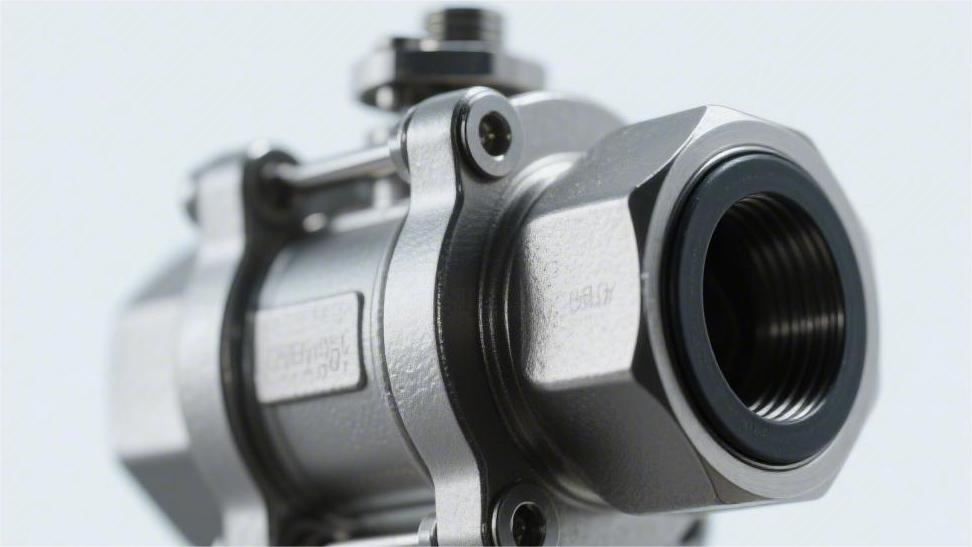
The sphere surface needs to be sprayed with tungsten carbide to a thickness of 0.05 mm, achieving a hardness exceeding 68 HRC to resist wear;
The seal adopts a dual PEEK and metal structure, requiring regular maintenance by injecting grease through the injection valve;
Under highly corrosive conditions, core internal components should be directly replaced with Duplex Steel 2205 or Inconel alloy.
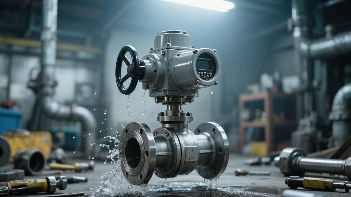
Surface Treatment
The engineering industry typically uses HVOF (High Velocity Oxygen Fuel) spraying to deposit a 150 to 250-micrometer thick tungsten carbide layer, achieving a surface hardness of 1000 to 1400 HV0.3 and controlling porosity below 1%.
For NACE MR0175 sour service conditions containing hydrogen sulfide (H2S), a 75-micrometer thick Electroless Nickel Plating (ENP) layer with 10-12% phosphorus content is often applied to block media erosion.
For high-temperature fluids above 500°C, a Stellite cobalt-based alloy thicker than 3 millimeters is applied via Plasma Transferred Arc (PTA) welding to maintain metal red hardness.
HVOF Supersonic Spraying
The pressure inside the combustion chamber is usually maintained between 0.6 and 1.0 MPa. The mixed gas expands and accelerates through a Laval nozzle. The final exit velocity of the airflow can exceed Mach 2.0, reaching 1500 to 2000 meters per second.
Powder particles carried in the supersonic airflow are heated to a semi-molten state between 1600°C and 2500°C within milliseconds. Upon high-speed impact with the substrate surface, the kinetic energy of a single tungsten carbide powder particle usually exceeds 1.5 microjoules. The semi-molten particles undergo severe plastic deformation at the moment of impact.
Engineers usually select 15 to 45-micrometer or 20 to 53-micrometer spherical agglomerated sintered powders. The tungsten carbide grain size within the powder needs to be controlled between 0.2 and 1.0 micrometers. Finer primary grains provide higher microhardness and reduce microscopic brittle spalling when subjected to solid particle impacts in the fluid.
- Gun traverse speed: 500 – 800 mm/s
- Spraying standoff distance: 200 – 380 mm
- Powder feed rate: 40 – 80 g/min
- High-pressure oxygen flow: 800 – 1000 slpm
- Fuel gas injection pressure: 0.4 – 0.7 MPa
An excessively high feed rate causes uneven particle heating, increasing internal porosity to over 2%. API 6D ball valve standards require porosity to be strictly controlled within 0.5% to 1.0%. Extremely low porosity cuts off the physical path for fluid media to penetrate into the 316 or 17-4PH stainless steel substrate.
Commonly used coating formulations fall into two major camps: tungsten carbide and chromium carbide. In sand-containing crude oil pipelines below 400°C, 86WC-10Co-4Cr is the most common formulation. The 10% cobalt provides toughness, and the 4% chromium enhances resistance to chloride ion erosion. When the system operating temperature rises to the 400°C to 850°C range, tungsten carbide undergoes a decarburization reaction, generating a brittle W2C phase.
High-temperature environments exceeding 400°C require switching the coating material to a 75Cr3C2-25NiCr formulation. Chromium carbide-nickel chromium coatings exhibit an extremely low oxidation weight gain rate in 800°C thermal cycling tests. Substrate surface pretreatment is also a standardized operation. Prior to spraying, dry sandblasting using 24 to 60 mesh aluminum oxide grit must be performed.
The surface roughness of the sphere after sandblasting needs to reach Ra 3.0 to 6.0 micrometers, providing sufficient anchor profile depth for subsequent mechanical interlocking. The spraying operation is usually completed in multiple passes, with a single-pass coating thickness controlled between 15 and 25 micrometers. The total accumulated thickness ranges from 150 to 250 micrometers. A coating thickness exceeding 300 micrometers causes a sharp increase in internal residual compressive stress, inducing macroscopic cracking.
- Tensile test fracture strength: > 70 MPa (ASTM C633)
- Coating cross-section microhardness: 1000 – 1400 HV0.3 (ASTM E384)
- Metallographic image porosity: < 1.0% (ASTM E2109)
- Neutral salt spray corrosion resistance: > 1000 hours (ASTM B117)
- Rubber wheel dry sand wear: Volume wear < 5 mm³ (ASTM G65)
The surface of a freshly sprayed sphere is very rough and cannot meet Class V or Class VI leakage rate standards. Subsequent precision grinding taking hours to dozens of hours is required. Spherical external cylindrical grinding is performed using a 400 to 1000 grit diamond grinding wheel. After removing approximately 50 micrometers of allowance, the sphere dimensions return to the design tolerance range.
After grinding, diamond lapping paste must be used to lap the sphere against a matching metal seat. The lapping process eliminates macroscopic waviness, creating a 100% perfect contact band on the sealing surface. The final sealing surface roughness Ra reaches 0.05 to 0.1 micrometers, achieving mirror-level optical flatness.
In the Alberta oil sands projects in Canada, the medium contains up to 15% quartz sand particles. The local fluid velocity passing through a reduced-bore ball valve can reach 15 m/s. Untreated A105 carbon steel ball valves suffer severe internal leakage due to erosion grooving after just 300 hours of operation. Ball valves utilizing a 200-micrometer 86WC-10Co-4Cr coating operate fault-free for over 8000 hours under the exact same conditions.
When high-speed solid particles strike the coating surface at angles of 30 to 90 degrees, the hard tungsten carbide grains resist micro-cutting forces. The cobalt-chromium alloy matrix acting as a binder absorbs the impact kinetic energy, delaying the propagation of fatigue cracks. ASTM G76 erosion wear test data indicates that under a 90-degree angle impact, the erosion rate of this coating is only 0.02 mm³/g.
ENP Electroless Nickel Plating
The autocatalytic deposition reaction using sodium hypophosphite as a reducing agent takes place in a weak acidic aqueous solution at 85°C to 92°C. The pH value of the bath is strictly controlled between 4.5 and 5.0. Nickel ions are continuously reduced without applying electrical current and uniformly cover the geometric surface of the carbon steel or low-alloy steel sphere.
Complex topographies such as the root of flanges, the inner wall of the sphere flow passage, and the undercut of the fixed trunnion all achieve an coating of equal thickness. The deposition rate is usually maintained at 10 to 15 micrometers per hour. The edge thickening phenomenon caused by the Faraday electroplating effect is eliminated, and the profile tolerance of the sphere’s outer diameter can be controlled within ±2 micrometers.
Industrial valves commonly use a high-phosphorus formulation with a phosphorus mass fraction of 10% to 14%. After the liquid metal deposition cools, it presents an amorphous microstructure without grain boundaries. Physical channels for intergranular corrosion are blocked, and the chloride ion permeation rate is less than 0.01 mm/year under a 50 MPa differential pressure.
According to the ASTM B733 standard specification, a high-phosphorus coating is considered to be in a pore-free state when the deposition thickness exceeds 25 micrometers, with a porosity lower than 0.1 pores/square centimeter.
Conventional salt spray exposure conditions on North Sea offshore platforms require a minimum thickness guarantee of 25 micrometers. Gas gathering station networks in Texas containing 5% carbon dioxide elevate the design thickness to 50 micrometers. NACE MR0175 sour gas pipelines in the Middle East containing high concentrations of hydrogen sulfide mandate 75 micrometers.
After coating deposition, it must enter a temperature-controlled heating furnace within 2 to 4 hours. For ASTM A105 forged steel substrates, the baking temperature is set in the range of 190°C to 210°C. Maintaining a constant temperature for 4 to 8 hours effectively expels free hydrogen atoms trapped in the crystal lattice, avoiding hydrogen-induced cracking.
- Initial coating microhardness: 500 – 600 HV0.1
- Static friction coefficient: 0.13 – 0.15 (non-lubricated state)
- Dynamic friction coefficient: 0.08 – 0.12 (grease-containing conditions)
- Operating torque reduction: Decreased by 15% – 20% compared to a bare carbon steel surface
- Abrasive wear volume: < 15 mg (Taber wear test CS-10 wheel, 1000 cycles)
If the baking temperature is raised to 400°C and held for 1 hour, the amorphous structure will precipitate Ni3P intermetallic compounds possessing hard spot characteristics. The surface microhardness consequently climbs to 900 to 1000 HV. The crystallization process is accompanied by a volumetric shrinkage of 0.5% to 1.0%, generating microcracks within the coating.
Microcracks destroy the natural anti-corrosion barrier of the high-phosphorus coating. Sulfur-containing media will penetrate along the micron-scale crack channels to the A350 LF2 low-temperature carbon steel substrate, triggering pitting corrosion. For valve internals handling corrosive fluids, engineers strictly prohibit heat treatment operations exceeding 250°C.
In a boiling water test containing 3.5% sodium chloride lasting 1000 hours, the surface pitting depth of a 75-micrometer coating treated at 200°C did not exceed 0.5 micrometers.
The operating temperature of gas transmission pipelines in Siberia, Russia, frequently remains in extreme cold environments of -46°C to -60°C year-round. The toughness of high-phosphorus coatings does not diminish at low temperatures, and the Charpy impact energy at -50°C is maintained at over 95% of the substrate. After a PTFE soft seat undergoes 5000 opening and closing cycles of reciprocating friction against the coating surface, the coating wear is less than 2 micrometers.
For concentrated sulfuric acid media with a mass concentration up to 98%, the static corrosion rate of the high-phosphorus surface at room temperature is 0.02 mm/year. The 10% hydrochloric acid commonly used in pipeline pickling operations will erode the nickel alloy layer at a rate of 1.5 mm per year. The valve must be kept in the fully open position before pipeline acid pickling to protect the sealing surface.
- Bath filtration accuracy: 1 – 5 micrometers continuous circulation filtration
- Metal turnover cycles: A maximum of 6 cycles of solution replenishment are allowed
- Phosphite accumulation limit: Not to exceed 120 g/L to prevent solution decomposition
- Substrate loading ratio: 0.5 – 2.5 square decimeters/liter of bath volume
- Deposition stress state: Maintain near-zero internal stress of -10 to +10 MPa
Hot alkaline solution with a concentration of 12% to 15% is used to remove cutting oils and rust-preventive greases. It is subsequently immersed in hydrochloric acid at a concentration of 5% to 10% at room temperature for 15 to 30 seconds to strip off the micron-level oxide film invisible to the naked eye.
After rinsing with deionized water, the silver-gray carbon steel parts must be submerged in the 90°C plating bath within 60 seconds. Coating adhesion is tested via a bending test according to the ASTM B571 standard. The specimen is bent 180 degrees around a cylinder with 4 times the thickness. Observed under 4x magnification, no metal peeling or flaking occurs at the interface.
The 24-inch Class 600 trunnion mounted ball valves at a Canadian LNG receiving terminal utilize a 50-micrometer thickness treatment scheme. The stem operating torque measured under a full differential pressure of 10 MPa is 12,500 Nm. The opening torque of an untreated bare steel ball valve of the same specifications under the same conditions reaches 14,800 Nm.
Alloy Hardfacing
In high-temperature pipelines of Fluid Catalytic Cracking (FCC) units in refineries, the media operating temperature is maintained between 540°C and 710°C for long periods. Conventional tungsten carbide sprayed coatings undergo oxidative decarburization when exceeding 400°C, leading to a sudden drop in surface hardness of over 40%. Engineers typically use the Plasma Transferred Arc (PTA) welding process to overlay a 3.0 to 5.0-millimeter thick cobalt-based hard alloy onto the surface of an ASTM A105 or F316 stainless steel sphere.
The PTA process uses a high-frequency arc to ionize argon gas into a plasma beam reaching temperatures up to 10,000°C. The high-energy plasma beam instantaneously melts Stellite 6 alloy powder fed through a 1.2 mm input orifice, forming a metallurgical bond with the substrate surface. The dilution rate is strictly controlled between 5% and 8% to prevent the iron element in the substrate from overly diluting the anti-corrosion performance of the cobalt-based alloy.
Skipping a buffer layer and directly hardfacing onto a carbon steel substrate generates tremendous thermal stress, leading to macroscopic cracks visible to the naked eye during the cooling phase. Welders must first lay down a buffer layer of ER309L stainless steel or Inconel 625 nickel-based alloy with a thickness of 1.5 to 2.0 millimeters using Tungsten Inert Gas (TIG) welding. The buffer layer provides a thermal expansion coefficient transition of 15.0 µm/m·°C.
This smooth transition in thermal expansion coefficient eliminates residual tensile stresses as high as 350 MPa at the sealing surface. The most commonly used hardfacing material is Stellite 6 cobalt-chromium-tungsten alloy, which maintains extremely high physical stability under extreme temperatures:
- Carbon content: 0.9% – 1.4%
- Chromium content: 27.0% – 31.0%
- Tungsten content: 3.5% – 5.5%
- Room temperature hardness: 38 – 45 HRC
- 600°C microhardness: > 300 HV
High-hardness M7C3 type chromium carbide particles are dispersedly distributed within the cobalt-based solid solution. When 50 to 200-micrometer catalyst powders entrained in the fluid scour the sphere surface at 25 m/s, the carbide skeleton provides exceptionally strong resistance to micro-cutting. Tests show that the volume wear of Stellite 6 at 600°C is only one-twentieth that of carbon steel.
High-temperature and high-pressure steam systems (such as a main steam line at a pressure of 15.0 MPa and a temperature of 560°C) impose extremely high demands on the anti-galling ability of valve sealing surfaces. The ball and metal seat open and close frequently under a high torque of 2000 N·m, making them highly susceptible to metal galling. The naturally low friction coefficient and anti-adhesion characteristics of cobalt-based alloys prevent tearing of the sealing surfaces.
Different hardfacing materials have strict distinctions regarding their physical limits and applicable working conditions. Engineers will select the corresponding alloy grade based on the hydrogen sulfide content, chloride ion concentration, and peak temperature in the fluid:
| Alloy Grade | Overlay Thickness (mm) | Iron Content Limit | Typical Application Environment | Max Withstand Temp |
|---|---|---|---|---|
| Stellite 6 | 3.0 – 5.0 | 3.0% | High temp abrasive wear, steam | 800°C |
| Inconel 625 | 2.5 – 4.0 | 5.0% | Seawater, high concentration chlorides | 982°C |
| Hastelloy C276 | 2.0 – 4.0 | 7.0% | Strong acids, wet hydrogen sulfide | 1093°C |
For A105 carbon steel substrates, the furnace temperature needs to rise to 620°C at a rate of 50°C per hour, hold for 2 to 4 hours, and then cool with the furnace to below 300°C. The annealing process releases over 80% of the welding thermal stress and restores the impact toughness of the heat-affected zone (HAZ).
Quality inspectors use Penetrant Testing (PT) compliant with ASME Section V to check for surface microcracks and Ultrasonic Testing (UT) to scan for lack-of-fusion defects at the bonding interface. The API 6D standard stipulates that isolated pores or slag inclusions exceeding 1.5 millimeters in diameter are not permitted on the surface of the hardfaced layer.
Spheres that pass flaw detection are sent into a CNC vertical lathe for rough machining, removing a machining allowance of 1.0 to 1.5 millimeters. Turning Stellite 6 requires the use of PCBN (Polycrystalline Cubic Boron Nitride) tools, with the cutting speed controlled at 30 to 50 m/min and a feed rate of 0.1 mm/rev. An excessively high cutting speed will cause the insert to chip due to thermal wear within 10 minutes.
The precision-machined sphere must undergo matched lapping with the corresponding 316 stainless steel or Inconel 718 metal seat. Operators apply 400 grit silicon carbide lapping paste and perform eccentric rotational lapping for 8 to 12 hours on a dedicated sphere lapping machine. The contact band width of the lapped sealing surface must be uniformly distributed between 3.0 and 5.0 millimeters.
At the gas injection wellheads in Saudi Arabia’s Ghawar Field, gases with pressures up to 69.0 MPa and containing 8% hydrogen sulfide require valves to achieve an ISO 5208 Rate B leakage rate. A composite structure ball valve featuring Inconel 625 internal cladding with a secondary Stellite 6 overlay on the sealing surface area still maintains a sealing metric of less than 10 bubbles per minute after undergoing 500 pressurized full-differential open/close cycles.
Sealing Technology
In Class 1500 (25.5 MPa) high-pressure pipelines, conventional PTFE is prone to cold flow deformation at 120°C; using Devlon V-API or PEEK thermoplastics can increase the yield strength to over 130 MPa.
When handling media with solid phase particles, the Double Block and Bleed (DBB) structure under the API 6D specification, combined with tungsten carbide surface hardening (hardness > 70 HRC), can achieve the FCI 70-2 Class VI zero leakage standard.
The system relies on Inconel X-750 springs to provide an initial preload specific pressure of 0.5-1.5 MPa to compensate for material deformation between -46°C and 200°C.
Seat Material Selection
Non-metallic polymers exhibit cold flow deformation when continuously subjected to pressure. The physical structure of pure Polytetrafluoroethylene (PTFE) remains stable only up to 120°C and within the Class 150 (approx. 2.0 MPa) pressure range.
When pipeline system pressure reaches 2.5 MPa, the creep rate of pure PTFE will exceed 8% within 100 hours. Blending 15% to 25% glass fiber or carbon fiber by volume into PTFE creates Reinforced Polytetrafluoroethylene (RPTFE).
After adding fibers, the surface friction coefficient of RPTFE drops to 0.04. Coupled with changes in the microscopic molecular structure, its maximum withstand temperature increases to 200°C, and the applicable maximum pressure rating is raised to Class 300 (approx. 5.0 MPa).
Under -196°C Liquefied Natural Gas (LNG) receiving terminal conditions, the polymer chain segments of RPTFE will completely freeze and fracture. Polychlorotrifluoroethylene (PCTFE) possesses a unique molecular crystal structure, making it a replacement for leak-proof components in ultra-low temperature environments.
PCTFE can still maintain a compressive yield strength of 30 MPa at -196°C. According to ISO 5208 standard testing, it can strictly control the microscopic leakage rate of high-pressure helium below 1×10^-6 mbar L/s.
When transporting crude oil on offshore oil and gas platforms, high-pressure pipelines ranging from ASME Class 600 to Class 1500 require materials with higher mechanical limits. Devlon V-API is a proprietary cast polyamide nylon with a room temperature yield strength reaching 110 MPa.
The water absorption rate of Devlon V-API after soaking in water for 24 hours is only 0.5%. It does not experience volumetric expansion in wet gas flows, and machining dimensional tolerances can be maintained within ±0.02 mm across the -46°C to 190°C range.
Polymer Material Parameter Comparison for Low-Pressure Conditions
| Material Name | Tensile Strength (MPa) | Shore Hardness (Shore D) | Min Applicable Temp | Max Applicable Temp |
|---|---|---|---|---|
| PTFE | 25 | 55 | -50°C | 120°C |
| RPTFE | 35 | 65 | -50°C | 200°C |
| PCTFE | 45 | 80 | -196°C | 150°C |
| Devlon | 110 | 85 | -46°C | 190°C |
When the H2S concentration in sour gas field pipelines exceeds 5%, the molecular chains of Devlon are decomposed by high-concentration hydrogen sulfide. Polyetheretherketone (PEEK), as a specialty engineering thermoplastic, complies with NACE MR0175 anti-corrosion specifications.
PEEK has a tensile strength of 100 MPa and can operate continuously for long periods at a high temperature of 260°C. When rapid depressurization occurs in a Class 2500 (42 MPa) pipeline, PEEK’s highly dense structure prevents the material from undergoing explosive decompression tearing.
Multiphase flows containing solid phase particles can easily penetrate polymer surfaces. When fluids contain quartz sand or catalyst powders with a diameter greater than 50 micrometers, thermoplastic materials are instantly scratched, leading to fluid breakthrough.
Metal-to-metal structures utilize the exact same forging substrate as the sphere, typically ASTM A105 carbon steel or F51 duplex stainless steel. The High Velocity Oxygen Fuel (HVOF) spraying process adheres a layer of tungsten carbide (WC-Co) coating 0.2 mm to 0.5 mm thick onto the substrate surface.
The surface Rockwell hardness of the tungsten carbide coating after cooling reaches 70 to 74 HRC. The bond strength between the coating and the substrate metal is up to 70 MPa, ensuring it will not experience laminar flaking under the erosion of strongly abrasive media flowing at 30 m/s.
In high-temperature cracking units exceeding 400°C, the cobalt binder inside the tungsten carbide material begins to oxidize and lose weight. The Plasma Transferred Arc (PTA) welding process overlays Stellite 6 cobalt-chromium-tungsten alloy onto the substrate, typically to a thickness of 2.0 millimeters.
Stellite alloy maintains its red hardness of 35 to 45 HRC at 600°C. Under a physical contact specific pressure of 10 MPa, it possesses extremely high anti-galling ability when generating relative sliding against a metal sphere of equivalent hardness.
High-Pressure and Metal Material Parameter Comparison
| Material Name | Surface Hardness | Tensile Strength (MPa) | Max Applicable Temp | Friction Coefficient (Dynamic) |
|---|---|---|---|---|
| PEEK | 85 Shore D | 100 | 260°C | 0.35 |
| Tungsten Carbide | 72 HRC | Coating Adhesion 70 | 400°C | 0.20 |
| Stellite 6 | 42 HRC | Overlay Tensile 700 | 600°C | 0.25 |
The machining center uses diamond lapping paste with a grit size as small as 1 micrometer to perform matched reciprocal lapping on the sphere and seat surfaces, achieving a surface roughness of Ra 0.05.
The reciprocal lapping procedure ensures the contact faces on both ends reach a 100% spherical conformity rate. According to the FCI 70-2 leakage testing specification, the Class V standard allows a maximum leakage of 0.0005 milliliters of water per minute per inch of nominal pipe size per psi of differential pressure.
Spring Preload Compensation
In ASME B16.34 standard pipelines, when the pressure is below 0.5 MPa, hydrostatic pressure cannot generate sufficient thrust. The system relies on rear-mounted components to apply an initial mechanical specific pressure of 0.8 to 1.2 MPa to keep the sealing polymer firmly pressed against the sphere surface.
When fluid pressure fluctuates in the 0 to 0.5 MPa range, the sealing surface is in a low-pressure critical state. Physical thrust compensates for the lack of fluid differential pressure, maintaining bubble-tight zero leakage under the FCI 70-2 Class VI standard. As the internal pipeline pressure rises above 2.0 MPa, the piston effect begins to dominate the thrust.
The piston effect refers to the hydraulic force generated by fluid pressure acting on the difference between the inner and outer diameters of the valve seat. When internal pressure reaches Class 600 (approx. 10 MPa), the unidirectional fluid thrust can be 10 to 15 times the initial mechanical thrust. The back components shift to an auxiliary state, absorbing high-frequency micro-vibrations of the parts caused by severe differential pressure.
API 6D long-distance transmission pipelines undergo drastic temperature changes during their service lifecycle. When ambient and media temperatures alternate between -46°C and 200°C, there is a multiple-fold difference between the linear expansion coefficients of the valve body metal and the valve seat polymer. The rear-mounted mechanical components absorb the corresponding physical dimensional shifts through their own elastic compression.
- Cylindrical Helical Springs: Provide long displacement compensation of 3.0 to 5.0 millimeters, suitable for 2-inch to 12-inch sizes.
- Belleville Springs: Output a high load of 15,000 Newtons within an extremely short compression stroke of 1.5 millimeters.
- Wave Springs: Reduce footprint space by 50%, commonly used in space-constrained API 10K high-pressure wellhead equipment.
When thermal expansion causes the total seat thickness to increase by 0.2 to 0.5 millimeters, the elastic elements are compressed backward. The excess squeezing force is converted into elastic potential energy stored in the metal lattice. When a sudden temperature drop causes the polymer material to shrink and thin, the stored potential energy is instantly released, pushing the valve seat forward by about 0.3 millimeters to fill the gap.
A 2000-kilometer natural gas pipeline generates immense axial tensile and bending stress. When pipeline stress is transmitted to the flanges at both ends of the valve, 24-inch and larger sizes experience microscopic ovalization deformation of 0.05 to 0.15 millimeters inside the valve body. Adaptive expansion and contraction ensure the sealing surfaces do not lose contact.
A fully welded natural gas ball valve with a 36-inch size has an average of 30 to 48 cylindrical helical elements distributed evenly on the back of each seat. When calculating the spring constant, the total thrust must be equally distributed to each independent unit. The deviation load of a single material is controlled within ±5% to maintain an equal specific pressure around the entire sealing ring.
After undergoing 10,000 load-bearing open/close cycles with a 0.5 MPa differential pressure, the wear depth on the PEEK or RPTFE surface reaches 0.1 to 0.2 millimeters. Fixed structures lacking mechanical compensation would immediately experience micro-leakage at a rate of 50 milliliters per minute at this point.
The rear-mounted system continuously advances the seat in 0.01-millimeter increments, offsetting the 0.2-millimeter material loss in real-time. To prevent chloride ion stress corrosion cracking triggered by acidic gases containing H2S or CO2, the proportion of nickel in the material composition is significantly increased. Conventional 316 stainless steel has a lifespan of no more than 6 months under sulfur-containing conditions.
- Inconel X-750: Nickel content exceeds 70%, withstanding high temperatures of 540°C and high-concentration sour gas.
- Inconel 718: Yield strength of 1034 MPa, fatigue cycle endurance reaching millions of times.
- Nimonic 90: Cobalt content of 15% to 21%, maintaining high elasticity at extreme temperatures of 750°C.
- Elgiloy Cobalt Alloy: Extremely high corrosion resistance, used for harsh NACE MR0175 marine environments.
The NACE MR0175 specification dictates that Inconel X-750 wire must undergo solid solution treatment and two-stage precipitation hardening after forming. Holding at 1150°C for 2 hours followed by air cooling eliminates internal torsional stress residual from the winding and forming process. The treated material grain size reaches ASTM grain size number 5 or higher.
The precipitation hardening process precipitates extremely fine phase structures, raising the room temperature tensile strength of Inconel 718 to 1375 MPa. When continuously immersed under pressure in a 15 MPa high-pressure medium for 50,000 hours, the relaxation rate of the elastic component is strictly controlled to below 3% of the original load.
In process pipelines containing pulverized coal or high concentrations of catalyst powder, solid particles with diameters between 10 and 50 micrometers easily penetrate into the rear grooves. The continuous accumulation of fine particulate matter fills the metal compression stroke space. Once the mechanical components are jammed by particles, the compensation function immediately fails, triggering pipeline leakage.
To prevent solid particle deposition, heavy-wear conditions utilize wiper rings or flexible graphite seal rings to physically isolate the components from the main pipeline fluid. Some API 6D equipment employs a design featuring O-ring protective covers, enclosing the chamber into an independent dust-free space to block dust intrusion paths.
Anti-Explosive Decompression Sealing
Small molecule gases such as methane, carbon dioxide, and hydrogen sulfide will permeate the microscopic pores of rubber surfaces under Brownian motion. The gas molecular diameter (e.g., 0.33 nanometers for CO2) is far smaller than the free volume space between polymer macro-molecular chains.
When gas pressure reaches Class 900 (approx. 15 MPa) or above, the rate of gas permeation into the elastomer rises exponentially. After a pressurized saturation period of 72 to 120 hours, the microscopic pores inside the O-ring will be completely filled with high-pressure gas. At this time, the physical volume of the elastomer typically experiences a 3% to 5% expansion.
When a pipeline executes an Emergency Shutdown (ESD) or routine venting operation, the pressure within the valve cavity drops abruptly within an extremely short time. In the NORSOK M-710 standard test, the depressurization rate dropping from 15 MPa to atmospheric pressure can reach 2 MPa to 7 MPa per minute. The rapid disappearance of external air pressure breaks the pressure equilibrium inside and outside the O-ring.
The high-pressure gas trapped inside the rubber instantly expands violently, with the volumetric expansion rate exceeding 100 times within milliseconds. If the tensile tear strength of the polymer is lower than the expansion stress generated by the internal gas expansion, tiny bubbles will form on the surface and inside the O-ring.
Under rapid expansion, bubbles interconnect, forming internal cracks several millimeters long along stress concentration areas, ultimately leading to visible bursting or deep tearing phenomena on the seal surface.
Structural damage caused by abrupt physical depressurization is known as Explosive Decompression (ED) or Rapid Gas Decompression (RGD). After RGD occurs, the O-ring cross-section loses its original circular profile, and the compression set climbs to over 40%. The seal, having lost its elasticity, cannot maintain a 2.0 MPa contact specific pressure behind the valve stem or valve seat, resulting in fluid external leakage.
Conventional Nitrile Butadiene Rubber (NBR) or Fluoroelastomer (FKM) usually has a hardness between 70 and 80 Shore A. Their molecular cross-linking density is low, and internal free volume accounts for a large proportion, making them highly prone to blistering and bursting when encountering conditions with a pressure drop rate exceeding 1 MPa/min.
Anti-Explosive Decompression (AED) seals enhance the physical resistance of the polymer from the formulation source. By increasing vulcanization time and adjusting the cross-linking agent ratio, the macromolecular chains inside AED-grade rubber form a much denser three-dimensional network structure. This structure compresses the diameter of internal microscopic pores to below 0.1 nanometers, drastically reducing the gas permeability rate.
- The proportion of carbon black or white carbon black (silica) fillers is increased, bringing the Shore hardness to 90 to 95 Shore A.
- High cross-linking density raises the breaking tensile strength of the material to the 20 MPa to 25 MPa range.
- After being pressurized at 200°C for 72 hours, the compression set is controlled within 15%.
AED seals compliant with the NACE TM0297 specification primarily use Hydrogenated Nitrile Butadiene Rubber (HNBR) and specialty Fluoroelastomers (FKM) as base materials. In pipelines with a hydrogen sulfide concentration below 5% and a temperature not exceeding 150°C, 90 Shore A HNBR exhibits extremely high mechanical toughness, capable of withstanding mechanical extrusion up to 35 MPa.
Facing sour gas fields exceeding 150°C with H2S concentrations reaching over 10%, the carbon-carbon backbone of HNBR will undergo thermal degradation. High-fluorine-content AED-grade FKM can still maintain a tensile strength above 18 MPa in a 200°C environment.
Perfluoroelastomers (FFKM) possess a fluorine content of 73%. When enduring extreme pressures up to 42 MPa and high temperatures of 250°C, they still rely on robust carbon-fluorine bonds to block acid gas permeation.
Applying a closing pressure of 20 MPa inside a 180°C mold and holding for 15 to 20 minutes constitutes the primary vulcanization stage, ensuring a dense, pore-free internal structure. Subsequently, post-curing (secondary vulcanization) is performed in an oven at 200°C to 230°C for up to 16 to 24 hours to completely eliminate internal stresses.
High hardness causes AED O-rings to lack the flexibility of conventional rubber during installation. On valve assembly lines, workers need to use dedicated tapered nylon guide sleeves and apply a minimal amount of silicone-based grease to the groove edges.
Forceful overstretching will cause microcracks, imperceptible to the naked eye, on the surface of high-hardness rubber. Specifications require that the maximum stretching rate during installation must not exceed 5% of the inner diameter. For large-bore 36-inch valves, vulcanized splicing processes are typically used to manufacture oversized O-rings, and the tensile strength at the splice must reach over 90% of the parent material.
Compared to the 15% to 30% compression rate of conventional O-rings, the groove depth for AED seals is enlarged, strictly limiting its initial compression rate to between 10% and 15%.
- Reserving more groove space allows the rubber to have sufficient volumetric expansion leeway after absorbing high-pressure gas, with the fill rate controlled at 75% to 85%.
- The matching clearance between the valve stem and the stuffing box is reduced to 0.05 mm to 0.08 mm.
- Utilizing back-up rings made of PEEK or PTFE prevents the rubber on the 90-degree high-pressure side from being extruded into the assembly clearance.
In the NORSOK M-710 standard certification testing, the AED O-ring is placed inside a test autoclave. A gas mixture (typically 10% CO2 and 90% methane) is pressurized to 15 MPa at 100°C. After holding for 72 hours to achieve saturation, the gas inside the autoclave is instantaneously emptied at an extremely fast rate of 20 MPa/min under the control of a pressure reducing valve.
After depressurization is complete, the pressure inside the autoclave is raised back to 15 MPa, and ultra-fast depressurization is performed again. The entire test requires 8 to 10 consecutive cycles. After testing, the O-ring is cut open, and its cross-section is observed under a 10x microscope. It only passes certification if the internal crack length is less than 10% of the cross-sectional diameter and no traversing tears have occurred.
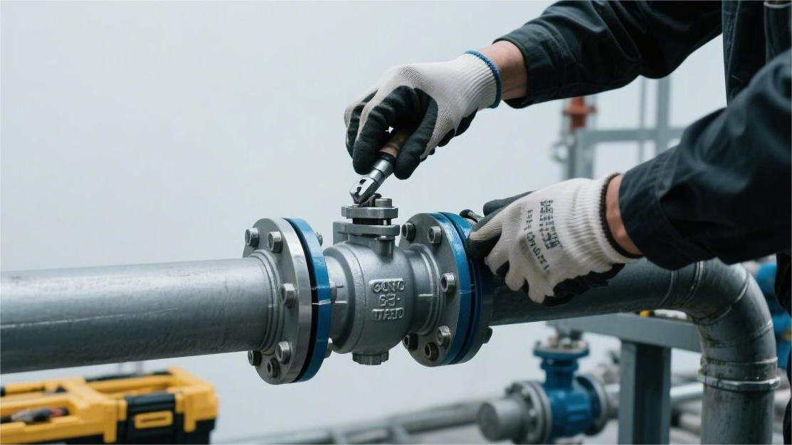
Alloy Materials
By selecting the right alloy substrate, the service life of a trunnion mounted ball valve can typically be extended 3 to 5 times.
Under conditions where the H₂S partial pressure exceeds 0.05 psi, conventional 316 stainless steel will rapidly develop stress cracking.
Using Super Duplex steel (such as UNS S32750) with a PREN (Pitting Resistance Equivalent Number) index greater than 40, or Inconel 718 with a yield strength of 120,000 psi, enables the valve to operate continuously for over 60 months in API 10,000 psi high-pressure and 200°C+ environments.
Anti-Sour and Anti-Corrosion
When the H₂S partial pressure exceeds 0.05 psi and the total pressure is greater than 65 psi, the NACE MR0175/ISO 15156 international standard is mandatorily enforced. The iron sulfide passivation film on ordinary carbon steel surfaces will detach under high flow velocities, triggering severe Hydrogen-Induced Cracking (HIC).
Engineers suppress Sulfide Stress Cracking (SSC) by controlling the material’s Rockwell Hardness. The hardness of carbon steel valve bodies (such as ASTM A350 LF2) for API 6D trunnion mounted ball valves is limited to below 22 HRC in sour environments. The upper hardness limit for austenitic stainless steel (such as 316L) is likewise 22 HRC, aiming to prevent hydrogen atoms from accumulating within the metal crystal lattice.
When the chloride ion (Cl-) concentration in the produced fluid reaches 50 ppm and the operating temperature exceeds 60°C, 316L stainless steel is extremely susceptible to Chloride Stress Corrosion Cracking (SCC). Engineering specifications require the selection of duplex stainless steels with higher PREN (Pitting Resistance Equivalent Number) values. The calculation of PREN is based on the mass percentages of chromium, molybdenum, and nitrogen.
2205 Duplex Stainless Steel (UNS S31803) is composed of nearly equal proportions of ferrite and austenite metallographic phases. Its chemical composition includes 22% chromium, 5% nickel, and 3% molybdenum, with a PREN value stabilizing around 35. It can withstand chloride solutions up to 150,000 mg/L and will not suffer pitting in conditions containing low concentrations of H₂S.
The lower yield strength limit of 2205 material is 450 MPa (65,000 psi), nearly twice that of conventional 316 stainless steel (205 MPa). High yield strength allows trunnion mounted ball valves to utilize thinner wall designs, reducing overall weight by approximately 15% in Class 1500 (approx. 250 Bar) pipeline systems.
- H₂S partial pressure upper limit: Maximum allowable is 1.5 psi.
- Maximum operating temperature: Does not exceed 232°C for long-term service.
- Minimum design temperature: Maintained above -50°C.
- Chloride tolerance: Below 150,000 mg/L.
Facing higher concentrations of corrosive media, Super Duplex stainless steel 2507 (UNS S32750) becomes the standard configuration. 2507 contains 25% chromium, 7% nickel, and 4% molybdenum, pushing the PREN index above 40. In strongly acidic brines with a pH below 3.5, the annual corrosion rate of 2507 is controlled below 0.01 mm, satisfying the 20-year design life for API 6D valves.
When the H₂S partial pressure breaks through 10 psi, or the working temperature exceeds 250°C, the ferrite phase of duplex stainless steel undergoes the “475°C embrittlement” phenomenon, experiencing a cliff-like drop in mechanical toughness. System design pivots to Nickel-Based Alloys, leveraging a high proportion of nickel to generate a dense nickel-rich oxide protective film on the metal surface.
Inconel 625 (UNS N06625) contains up to 58% nickel, 20-23% chromium, and 9% molybdenum. In wellhead equipment containing free sour gas with flow velocities reaching 25 m/s, alloy 625 completely resists high-speed erosive corrosion from the fluid. Its tensile strength reaches 827 MPa, displaying an extremely low creep rate in high-temperature, high-pressure sour media.
- Nickel content baseline: Maintained above 58%.
- H₂S partial pressure tolerance: Unlimited (per NACE specifications).
- Maximum withstand temperature: Can reach 538°C (1000°F).
- Tensile strength range: 827 MPa to 1034 MPa.
- Hardness control standard: Maximum 35 HRC in the annealed condition.
For moving internal components subjected to high shear forces and friction, such as the stem and support trunnions of a trunnion mounted ball valve, precipitation-hardening Inconel 718 (UNS N07718) is the premier choice. Through the addition of 5% niobium (Nb) and a small amount of titanium (Ti), the yield strength of the 718 alloy is elevated to over 120,000 psi after aging heat treatment.
Valves in API 10,000 psi ultra-high pressure systems must overcome high differential pressure torque the moment they open. The Inconel 718 stem withstands 120,000 psi of torsional stress while preventing brittle fracture induced by high-concentration H₂S. On North Sea High-Pressure High-Temperature (HPHT) platforms, this material greatly prolongs the stability of valve operational cycles.
In hydrofluoric acid (HF) alkylation units, stainless steels and most nickel-based alloys are rapidly dissolved. Monel 400 (UNS N04400) consists of 63% nickel and 28-34% copper. It exhibits chemical inertness with an extremely low corrosion rate in hydrofluoric acid at concentrations below 80% and temperatures below 150°C.
Commercially pure titanium (Titanium Grade 2) has a density of 4.51 g/cm³, half the weight of steel, and barely corrodes in flowing seawater. Even if seawater flow rates reach 30 m/s, the titanium dioxide (TiO₂) passivation film on the titanium alloy surface can self-heal within milliseconds of being damaged.
Driven by engineering budget considerations, large-bore Trunnion Mounted Ball Valves (TMBV) rarely use solid special alloys for integral casting or forging. Manufacturers adopt the Corrosion Resistant Alloy (CRA) Weld Overlay process, utilizing hot wire TIG welding technology to deposit a layer of Inconel 625 at least 3 mm thick onto all fluid-contacting surfaces inside an ASTM A105 forged carbon steel valve body.
Engineering specifications require that the iron content (Fe%) at a depth of 1.5 mm below the surface of the overlay layer must be controlled within 5% to 10%. Precise heat input parameters ensure the deposited layer retains the anti-corrosion chemical characteristics of the 625 alloy while leveraging the carbon steel substrate to withstand the physical pipeline stress of Class 2500 ratings (approx. 420 Bar).
Extreme Temperatures
When operating temperatures drop to -162°C (-260°F), pipeline system internal pressures are maintained at 1,440 psi (Class 600). When the temperature falls below -29°C, the Body-Centered Cubic (BCC) crystal structure of ordinary carbon steel (such as ASTM A105) deforms, losing its original physical flexibility.
The ability of the metal to absorb impact energy internally diminishes sharply as the environment gets colder, triggering a Ductile-to-Brittle Transition (DBTT). The ASME B31.3 pipeline specification requires that valve bodies serving at -46°C must use normalized ASTM A350 LF2 low-alloy steel. When pipeline metrics dive down to -101°C in ethylene plants, ASTM A350 LF3, containing 3.5% nickel element, becomes the mandatorily invoked engineering material.
The addition of nickel refines the ferrite grains, arresting the propagation of microscopic cracks. Before leaving the factory, all LF2 and LF3 forgings must undergo a Charpy V-notch impact test at their corresponding minimum design temperatures. The average absorbed energy of three standard specimens (10mm x 10mm x 55mm) must be greater than 27 Joules (20 ft-lbs), with no single specimen being lower than 20 Joules.
When the fluid is liquid nitrogen or LNG at -196°C, the toughness of low-alloy steel is completely lost. Engineers select 300 series austenitic stainless steels (such as ASTM A182 F304/F316) to manufacture valve bodies and internal components. Austenitic stainless steel has a Face-Centered Cubic (FCC) crystal structure, maintaining over 70% of its room temperature ductility in environments near absolute zero without suffering brittle fracture.
| Media Type | Minimum Design Temp | Valve Body/Trim Forging Material | Charpy Impact Test Temp | Min Absorbed Energy Requirement |
|---|---|---|---|---|
| Propane (LPG) | -46°C (-50°F) | ASTM A350 LF2 | -46°C | 27 J |
| Ethylene | -101°C (-150°F) | ASTM A350 LF3 | -101°C | 27 J |
| Liquefied Natural Gas | -196°C (-320°F) | ASTM A182 F316 | -196°C | Exempt for FCC structure |
| Liquid Hydrogen | -253°C (-423°F) | ASTM A182 F316L | -253°C | Carbon content must be <0.03% |
Shifting focus to the hydrocracking unit at the Jubail Refinery in Saudi Arabia, fluid parameters represent the opposite extreme. The temperature of the reactor effluent remains stable above 420°C year-round, and system pressure reaches as high as 2,500 psi. In high-heat physical environments, thermal motion of metal atoms intensifies, causing material yield strength to exhibit a linear downward trend.
Continuous high temperature and mechanical stress induce metal Creep, meaning the material slowly undergoes permanent plastic deformation under stress levels lower than its yield strength. To resist creep rupture, engineers utilize high-temperature alloy steels added with chromium (Cr) and molybdenum (Mo), such as ASTM A182 F11 (containing 1.25% chromium, 0.5% molybdenum) and F22 (containing 2.25% chromium, 1% molybdenum).
Molybdenum forms fine carbide precipitates in the steel’s ferrite matrix, hindering grain boundary sliding in high heat above 400°C. In the API 600 standard wall thickness calculation formula, the Allowable Stress for F22 material at 427°C (800°F) remains at 14,100 psi, which is 1.7 times that of ordinary carbon steel A105 (whose allowable stress drops to 8,200 psi).
When the superheated steam temperature of a Heat Recovery Steam Generator (HRSG) breaches 538°C (1000°F), the oxidation resistance of F22 hits its upper limit. ASTM A182 F91 forgings, containing 9% chromium and 1% molybdenum, take over for 600°C conditions. The chromium element generates a dense 1 to 2-micrometer thick chromium oxide (Cr₂O₃) thin film on the metal surface, stopping high-temperature oxidation scaling.
Catalytic reforming pipelines exceeding 600°C rule out all iron-based alloy steels. Incoloy 800H (UNS N08810), containing 30-35% nickel and 19-23% chromium, enters the procurement list. The carbon content of 800H is controlled between 0.05% and 0.10%, and it undergoes a solution annealing treatment at 1150°C to obtain an ASTM grain size of 5 or coarser.
- Creep limit: The 10,000-hour rupture strength of Incoloy 800H at 815°C reaches 45 MPa.
- Grain standard: Coarse grains (ASTM 5) reduce total grain boundary area, lowering the grain boundary sliding rate.
- Oxidation threshold: The addition of aluminum (0.15-0.60%) and titanium enhances carburization and nitridation resistance.
- Fatigue resistance: Adapts to heating and cooling cycles, preventing microscopic thermal cracks from forming inside the valve body.
The Coefficient of Thermal Expansion (CTE) of 316 stainless steel from 20°C to 400°C is approximately 16.2 µm/m·°C, whereas the CTE of A105 carbon steel is only 12.1 µm/m·°C. If a solid sphere made of 316 material is installed inside a carbon steel body of a trunnion mounted ball valve, the expanded volume of the sphere under high heat will be larger than the valve cavity.
The difference in volumetric expansion causes the sphere to instantly seize between the metal seats, and friction torque climbs exponentially. A micron-level thermal expansion gap is reserved during the machining stage. For a sphere with a nominal diameter of 24 inches (DN600), when the design temperature is 350°C, the machining tolerance of the sphere’s outer diameter must be additionally reduced by about 0.85 millimeters to compensate for the volume of material growth.
When temperatures exceed 400°C, the Cobalt Binder in tungsten carbide (WC-Co) coatings undergoes oxidative degradation, and hardness plummets from 1200 HV. In fluid pipelines above 500°C, coating materials are mandatorily switched to chromium carbide (Cr₃C₂-NiCr).
- Composition ratio: Utilizes a mix of 75% Cr₃C₂ and 25% NiCr alloy powder.
- Operating ceiling: Operates stably in oxidizing atmospheres up to 800°C (1470°F) without flaking.
- Porosity requirement: Porosity after HVOF spraying is limited to below 0.5%.
- Hardness testing: In a 600°C environment, microhardness is maintained above 850 HV0.3.
After HPHT (High-Pressure High-Temperature) valves are assembled, they must undergo PR2 performance qualification testing in accordance with API 6A Appendix F. The valve is placed in a programmable thermal cycling chamber; the chamber is filled with nitrogen gas and pressurized to 100% of the rated working pressure. The testing program covers ramping from room temperature to the maximum design temperature and consecutively completing 200 pressurized open/close cycles at the extreme temperature.
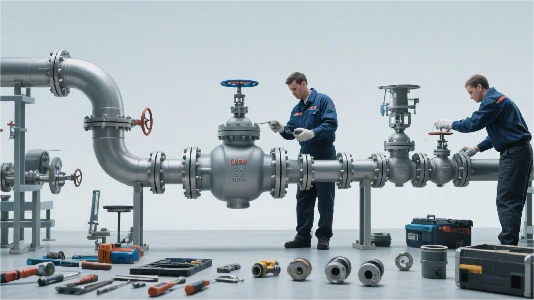
Internal Cladding/Overlay Process
The procurement unit price for pure nickel-based alloy (such as Solid Inconel 625) forgings typically exceeds 45 US dollars per kilogram.
Engineers employ the Corrosion Resistant Alloy (CRA) internal weld overlay process to balance engineering expenditures. Taking a fixed ball valve with a nominal diameter of 36 inches and a pressure rating of Class 900 as an example, using ASTM A350 LF2 carbon steel as the base material and overlaying Inconel 625 onto flow-wetted component surfaces slashes the material cost of a single valve by more than 60%.
Factories universally select Hot Wire Tungsten Inert Gas (Hot Wire TIG) technology for internal cavity cladding. Before feeding the wire into the weld pool, the system preheats the welding wire to 900°C to 1000°C via an independent power source. The preheating step elevates the weld deposition rate from 1.5 kg/h in traditional cold wire TIG to 3.5 kg/h.
A robotic arm extends into the valve cavity and deposits metal layer by layer according to set stepping parameters. The torch oscillation frequency is strictly set at 60 to 80 times/minute, and the welding travel speed is maintained at 150 to 250 mm/min.
In the molten state, iron (Fe) in the carbon steel base material permeates upwards into the high-nickel alloy overlay, causing iron element upward dilution fusion. A high proportion of iron destroys the original Face-Centered Cubic (FCC) crystal structure of Inconel 625, leading to a localized drop in the Pitting Resistance Equivalent Number (PREN).
API 6A and NACE MR0175 specifications mandate that the chemical composition at a depth of 1.5 mm below the metal layer surface must fully conform to the anti-corrosion standards of the pure special alloy material.
- Iron diffusion limit: At a depth of 1.5 mm from the machined surface, Fe content is controlled within 5% to 10%.
- Minimum effective cladding: After lathe precision machining and cutting, the retained physical thickness of the cladding must not be less than 3.0 mm.
- Weld bead overlap rate: The physical overlap area between adjacent weld beads must reach 50% to eliminate interpass lack-of-fusion defects.
- Shielding gas purity: Uses 99.995% high-purity argon gas, with gas flow maintained at 15 to 20 L/min.
Controlling Heat Input is the physical prerequisite to preventing base metal grain coarsening and embrittlement of the Heat-Affected Zone (HAZ). Welding voltage is maintained at 10 to 14 volts, and current is set at 180 to 250 amperes, restricting the total heat input to the 1.0 to 1.5 kJ/mm range.
After the cladding operation is complete, the carbon steel valve body with its metal layer is sent into a large annealing furnace to execute Post-Weld Heat Treatment (PWHT). The furnace temperature gently climbs to 620°C at a rate of 55°C per hour, and it is held for 2 to 4 hours depending on the base metal thickness (calculated at 1 hour per inch of thickness).
The heat treatment process releases residual tensile stresses exceeding 300 MPa generated when the weld pool solidified. The Rockwell Hardness of the carbon steel base material’s heat-affected zone smoothly drops from 28 HRC post-weld to below the 22 HRC allowed by NACE specifications, preventing sulfide stress cracking in sour environments.
Quality inspectors use Liquid Penetrant Testing (PT) to scan 100% of the metal surface; the developer exposes microscopic surface cracks or pores with widths as small as 0.01 mm and depths of 0.05 mm.
Targeting the bonding interface between the clad layer and the carbon steel base material, an Ultrasonic Testing (UT) probe emits sound waves at frequencies of 2 to 5 MHz. The echo waveforms on the instrument screen precisely pinpoint slag inclusions or lack of fusion defects larger than 1.6 mm in diameter on the bonding face.
A spectrometer is placed on the inner cavity surface of the finished valve to perform Positive Material Identification (PMI) testing. X-ray Fluorescence (XRF) technology reads element mass fractions within 3 seconds, ensuring the molybdenum (Mo) content on the metal face stabilizes in the 8.0% to 10.0% range, and the nickel (Ni) content is no less than 58.0%.
High-precision moving mechanical fit areas of fixed ball valves, such as the Seat Pocket and Stem Journal, pose extremely high demands on the machined surface roughness of the metal layer. Computer Numerical Control (CNC) machines utilize Polycrystalline Cubic Boron Nitride (PCBN) cutting tools to machine the sealing surface roughness (Ra) to below 0.4 µm.
The highly polished Inconel 625 surface effectively reduces the mechanical wear rate of O-rings or spring-energized seals subjected to pressure fluctuations. When the pressure inside the valve body cavity frequently jumps between 0 and 1,500 psi, the smooth interface blocks high-pressure fluid from escaping along microscopic grooves.

")