
The primary cause of gas leakage is the 15% plastic deformation of the sealing seat triggered by pressure surges.
A sealing ring with a hardness of Shore A 85 should be selected to prevent high-pressure permeation, but cold embrittlement failure at -20°C must be guarded against.
It is recommended to control the pressure drop within 0.5 MPa to mitigate cavitation, and to use an ultrasonic detector to monitor abnormal noises above 50 decibels, ensuring that zero-bubble sealing can still be achieved under 10% pressure fluctuations.
Pressure
When the system pressure exceeds the yield strength of the sealing seat material (for example, PTFE is approximately 15-22 MPa at 23°C), a plastic cold flow on the 0.1mm level will occur, resulting in permanent deformation of the sealing surface.
Conversely, if the pressure is below 0.3 Bar, the self-tightening sealing structure driven by the medium will fail to compensate for the microscopic surface roughness (typically Ra 0.8 or higher) due to insufficient preload, triggering bubble leakage outside the API 598 standard.
High Pressure Deformation
When the pipeline pressure is elevated to the Class 900 rating (approximately 15.3 MPa), the linear thrust exerted by the ball on the valve seat is converted into surface contact pressure. If this pressure exceeds the yield limit of the PTFE valve seat at 23°C, which is about 18 MPa, the material will undergo inelastic displacement.
This physical displacement manifests as the sealing seat being squeezed towards the valve body cavity, destroying the original flatness of the Ra 0.4 sealing surface. After a sustained high-pressure load for 48 hours, the edge of the sealing ring will experience an elongation of 0.2mm to 0.5mm. This phenomenon is known as “extrusion” in the valve maintenance industry. Once the material extrudes, the ball will shear off the protruding sealing surface when it rotates to open, resulting in the inability to form a continuous sealing ring during the next closure.
- RPTFE (15% glass fiber reinforced): Compressive resistance is improved by 30% compared to pure PTFE, but there is still a 2% deformation rate at 10 MPa pressure.
- PEEK (Polyether Ether Ketone): Suitable for extreme environments above 25 MPa, with a hardness of Rockwell M95, capable of effectively resisting geometric distortion under high pressure.
- Metal-to-Metal Seal: Utilizes Stellite 6 hard alloy overlay welding, maintaining micron-level deformation at 42 MPa pressure, suitable for high pressure differential shut-off.
When the pressure rises rapidly from 5 MPa to 20 MPa, the ball not only displaces horizontally but also compresses the thickness of the downstream sealing seat. This thickness reduction causes a slight offset in the central axis of the valve stem, typically between 0.05mm and 0.15mm. This axial offset compresses the upper packing set, subjecting the V-ring packing originally intended for gas sealing to uneven lateral forces, increasing the probability of gas leaking from the valve stem.
Because gas molecules have extremely strong penetrability, high-pressure deformation will generate microscopic cracks inside the valve seat. These cracks are usually under 10μm in diameter and are difficult to detect with the naked eye. According to the Class A test requirements of the EN 12266-1 standard, the bubble leakage rate should be zero. However, under the effect of high-pressure deformation, the effective contact width of the sealing pair will abnormally increase from 3mm to 5mm, which in turn reduces the specific sealing pressure per unit area.
- Sealing surface topology change: High pressure forces the ball to embed into the valve seat, changing the contact point from a “line” to a “band,” and the friction force simultaneously increases by 40%.
- Elastic modulus failure: When the ambient temperature rises to 150°C, the elastic modulus of PTFE decreases by 60%, and high-pressure deformation becomes irreversible.
- Packing load fluctuation: High pressure causes the valve body cavity to expand, and the connecting bolts stretch by about 0.02%, resulting in a decrease in pressure on the flange sealing surface.
- Ball offset risk: Under Class 2500 conditions, the total thrust generated by the pressure differential on the ball can reach several tons; if the support bearings deform, it will cause the valve to jam during opening and closing.
Within the pressure boundaries defined by the ASME B16.34 standard, the creep resistance of the material determines the degree of deformation. For hydrogen pipelines where the working pressure is maintained above 100 Bar year-round, Devlon V-API material is typically selected, as its water absorption rate is below 0.1% and it possesses extremely high dimensional stability. If ordinary engineering plastics are used, high pressure will cause molecular chain slippage, and after 500 closing cycles, the internal leakage rate of the valve will downgrade from Rate A to Rate D.
Because deformation increases the static friction coefficient between the ball and the valve seat (from 0.05 to over 0.15), the pneumatic actuator may not be able to overcome the starting torque under a 0.6 MPa air supply pressure. This torque surge caused by deformation is typically 1.5 times higher than the design calculation value, leaving the valve in a partially open/partially closed state, further exacerbating the physical damage caused by high-pressure gas scouring the sealing surface.
| Pressure Class | Working Pressure (PSI) | Recommended Sealing Material | Maximum Allowable Deformation Rate (%) |
|---|---|---|---|
| 150 | 285 | PTFE / NBR | < 5.0% |
| 600 | 1480 | RPTFE / NYLON | < 2.0% |
| 1500 | 3705 | PEEK / DEVLON | < 0.5% |
| 2500 | 6170 | Tungsten Carbide | < 0.01% |
Under frequent operating conditions of opening and closing once per minute, the sealing seat material will generate heat due to repeated compression and release, and the local temperature may be 20°C higher than the medium temperature.
Low Pressure Failure
The design standards for floating ball valves dictate that the ball must fit closely against the valve seat driven by downstream differential pressure. However, when the pipeline pressure falls below 0.3 Bar, the gas thrust cannot overcome the initial elastic resistance of the seat material. This insufficient thrust results in a micrometer-level physical gap between the ball and the valve seat.
According to the API 598 standard, low-pressure gas tightness testing is typically conducted at a pressure of 0.4 to 0.7 MPa. However, in actual operating conditions, the pressure of many systems during the startup phase is only 0.01 MPa. At this point, the gravitational force component generated by the ball’s own weight (for a 4-inch floating ball, its weight is approximately 3.5kg) may exceed the weak gas pressure thrust, causing the ball to shift within the valve cavity, and the sealing pair cannot form a continuous contact ring.
Experimental data indicates that when the specific pressure on the sealing surface is below 2.5 N/mm², helium molecules will permeate along the microscopic roughness texture of Ra 0.8 on the sealing seat surface. In a standard environment of 15°C, the rate of this low-pressure leakage can reach 0.1 standard cubic feet per hour (scfh). While not sufficient to cause a severe explosion, it will trigger gas concentration monitoring alarms.
- Insufficient Contact Stress: In a low-pressure environment, the compression of the PTFE valve seat is less than 0.02mm, which is unable to fill the machining tool marks on the sealing pair surface.
- Frictional Drag: The friction coefficient between the ball and the support ring (typically 0.12) will hinder the micro-displacement of the ball in a state of zero differential pressure.
- Gravitational Interference: In vertically installed pipelines, the ball drops due to gravity, resulting in a 20%-30% deviation between the upstream and downstream specific sealing pressures.
To compensate for the sealing force shortfall under low pressure, engineers typically install Wave Springs or Coil Springs behind the valve seat. According to the sealing level requirements of ISO 5208, these springs must provide an initial preload of at least 150N. If the springs undergo Sulfide Stress Cracking (SSC) in a sour gas environment and their elastic force decays by more than 15%, the valve’s leakage rate in the low-pressure range will increase exponentially.
The SPE (Single Piston Effect) logic of the valve seat design is fragile at low pressures. Because the effective pressure area (piston area difference) of the seat sealing ring generates insufficient axial force at low pressure to overcome the frictional resistance of the O-ring, the valve seat may get stuck in the retracted position. For a rubber ring with 90 Shore A hardness, its starting friction typically requires an initial pressure of 0.2 MPa to be counteracted.
- Material Hardness Matching: Low-pressure systems should use elastomers with a hardness of Shore A 70-80 rather than harder materials like PEEK.
- Sealing Surface Polish: Increasing the surface roughness of the ball to Ra 0.1 can reduce the minimum specific pressure required for sealing by about 45%.
- Bi-directional Seal Calibration: In low-pressure Double Block and Bleed (DBB) tests, it must be ensured that the spring load deviation of the sealing seats at both ends is less than 5%.
- Packing Preload Optimization: Reduce the compression force of the valve stem packing to a torque of 12 N/m to prevent the valve stem friction from interfering with the slight floating of the ball.
When the ambient temperature drops from 20°C to -10°C, the contraction of the sealing seat material causes further loss of preload. The linear expansion coefficient of PTFE is approximately 10 x 10⁻⁵ /°C; under the dual effects of low temperature and low pressure, the radial clearance of the sealing pair will increase by about 0.05mm.
Within the framework of ASME B16.34, low-pressure failure involves not only the primary seal but also the sealing stability of the bonnet gasket. If the bolt preload is calculated solely based on high-pressure conditions, the physical permeability of low-pressure gas will exploit the microscopic pores of the metal gasket. For Class 150 valves, if the bolt load is less than 30% of its yield strength, Fugitive Emissions at the gasket will still detect a methane concentration exceeding 100 ppm at 0.05 MPa.
For light gases like hydrogen, the risk of low-pressure failure is even higher. Because the kinetic diameter of a hydrogen molecule is only 0.289nm, its escape capability at low pressure is over 3 times that of air. Laboratory comparative tests show that at 0.02 MPa, the leakage amount of a ball valve using standard RPTFE seats is 500% higher than that of a valve utilizing a soft metal-clad elastomer structure.
- Leak Detection Point: Downstream vent port when the valve is in the closed position.
- Pressure Threshold: Bubble generation rate at < 0.5 PSI.
- Material Response: The resilience rate of NBR material at low pressure must remain above 95%.
- Mechanical Intervention: Manually rotate the valve stem 5-10 degrees and re-close it, then observe whether the leakage rate changes due to the ball resetting.
During a 10-minute stable pressure observation period, if an initial pressure of 0.1 MPa drops by more than 10%, it usually points to uneven spring loading or the presence of foreign matter on the sealing seat surface. This situation, where tiny impurities (like a 10μm iron filing) cannot be flattened due to insufficient pressure, might conversely achieve a “false seal” under high pressure due to forceful squeezing.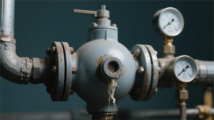
Rapid Gas Decompression Explosion
In a Class 1500 or higher pressure class environment, high-pressure gas molecules (such as carbon dioxide, hydrogen sulfide, or methane) will permeate into the interior of the floating ball valve’s elastomeric seals (like O-rings or seat inserts). Under a static pressure exceeding 15 MPa, these gas molecules occupy the free volume between the polymer chains of the elastomer. When the system pressure is reduced to atmospheric pressure within 2 minutes due to an Emergency Shut Down (ESD) or pipeline depressurization, the gas permeating the material does not have time to diffuse out, and its volume rapidly expands in milliseconds.
If the internal pressure generated by this volume expansion exceeds the tensile strength (typically 15-25 MPa) of the elastic material, structural fracturing will occur inside the material. This phenomenon is known as Rapid Gas Decompression (RGD) or Explosive Decompression (ED), manifesting as surface blistering, cracking, or the formation of internal radial cracks. Experimental data shows that at 20°C with a depressurization rate exceeding 70 Bar/min, conventional NBR (Nitrile Butadiene Rubber) sealing rings have an 85% probability of developing cracks visible to the naked eye.
- Gas Solubility Differences: The solubility of carbon dioxide in elastomers is 5-10 times higher than that of nitrogen; therefore, in systems injecting carbon dioxide, the frequency of RGD failures is far higher than in pneumatic systems.
- Cross-Sectional Diameter Impact: O-rings with a cross-sectional diameter greater than 5.33mm are more prone to RGD than thin-section seals because a larger cross-section increases the physical path length for gas to diffuse out of the material surface.
- Material Hardness Metrics: Soft materials with a hardness below Shore A 80 lack sufficient binding force during gas expansion, and the internal bubble growth rate is 3 times faster than in hard materials at Shore A 90.
| Gas Component | Typical Pressure (Bar) | Depressurization Rate (Bar/min) | RGD Risk Level | Recommended Seal Standard |
|---|---|---|---|---|
| Pure Methane (CH4) | 100 – 250 | > 50 | Medium | ISO 23936-2 |
| Carbon Dioxide (CO2) | 70 – 150 | > 20 | Extreme | NORSOK M-710 |
| Sour Gas (H2S) | 50 – 200 | > 30 | High | NACE MR0175 |
| Compressed Air | 10 – 40 | > 100 | Minimal | Standard NBR |
At the stem seal of a floating ball valve, this damage causes the leakage rate to soar from 0.1 mg/s to over 10 mg/s. Because RGD damage often begins inside the seal, early micro-cracks may not immediately cause external blowouts, but over the subsequent 50-100 pressure cycles, these internal cracks will propagate to the sealing surface, forming permanent physical channels. At an ambient temperature of -10°C, the brittleness of the elastomer increases, and the propagation rate of RGD-induced micro-cracks is 25% faster than at room temperature.
For Class 2500 pipeline systems, sealing materials must pass the NORSOK M-710 cyclic decompression test. This test requires experiencing 8 continuous “pressurize-hold-rapid depressurize” cycles in a 100°C environment. The material slices post-test are observed under a microscope at 10x magnification, and their crack Rating must achieve Level 0, 1, or 2 to be considered acceptable.
- Permeability Coefficient Control: Select highly polar elastomers (such as certain grades of FKM), whose gas molecule permeability coefficients are typically 2 orders of magnitude lower than VMQ (Silicone Rubber).
- Filler Reinforcement: Adding Carbon Black or specific proportions of fibers into the sealing material can enhance the tear resistance energy level of the polymer matrix, allowing the material to withstand internal expansion forces exceeding 12 MPa.
- Geometric Clearance Limitation: Control the metal extrusion gap of the O-ring groove to within 0.05mm to prevent the material, softened by RGD, from being nibbled under pressure pulses.
- Depressurization Rate Reduction Design: By installing a restriction orifice in the relief circuit, control the depressurization rate to below 5 Bar/min, providing sufficient diffusion time for the gas molecules.
If hard thermoplastics like NYLON 12 or DEVLON V-API are selected as valve seat inserts, although their RGD resistance is superior to rubber, under 150 Bar combined with a rapid temperature drop, the material will experience surface embrittlement due to the dual effects of thermal stress and gas expansion. This embrittlement manifests as fine “fish-scale patterns” on the sealing surface, causing abnormal wear on the valve seat by the ball during rotation, which subsequently increases the friction torque by approximately 25%.
In high differential pressure operating conditions such as underground natural gas storage facilities, to reduce the incidence rate of RGD, the valve design often utilizes a Double Piston Effect (DPE) valve seat combined with a Relief Valve. The relief valve is set to trigger when the cavity pressure is 1.5 MPa higher than the pipeline pressure, thereby avoiding severe permeation caused by pressure fluctuations of the cavity gas at the moment of valve closure.
| Material Category | Tensile Strength (MPa) | Recommended Max Working Pressure (MPa) | Depressurization Tolerance (Cycles) | Anti-RGD Rating Score |
|---|---|---|---|---|
| Standard FKM | 14 | 10 | < 2 | 2/10 |
| AED HNBR | 24 | 35 | > 50 | 9/10 |
| FFKM (Perfluor) | 18 | 42 | > 20 | 8/10 |
| PEEK (Hard) | 100 | 70 | > 500 | 10/10 |
When the system pressure suddenly drops from 20 MPa to 0.1 MPa, according to the Joule-Thomson effect, the local temperature may drop by 30°C to 50°C within seconds. This rapid cooling causes the seal to quickly drop below its Glass Transition Temperature (Tg), resulting in the material transitioning from an elastic state to a glassy state.
Sealing
Under high-pressure gas conditions, the sealing performance of floating ball valves is jointly determined by the Sealing Specific Pressure and Surface Roughness (Ra). For natural gas or industrial gases, the sealing pair must meet the ISO 15848-1 Class A or ANSI/FCI 70-2 Class VI (bubble-tight) standard. When the differential pressure exceeds 10MPa, the gas viscosity is extremely low, and micrometer-level sealing surface unevenness will lead to a leakage rate exceeding 10⁻⁴ mbar·l/s per minute.
Soft Seal vs Hard Seal
When evaluating the reliability of gas floating ball valves, the leakage class defined by the ANSI/FCI 70-2 standard is the primary metric distinguishing soft and hard seals. Soft seals are typically designed to Class VI, achieving bubble-tight shut-off at a test pressure of 0.35MPa, while hard seals mostly comply with Class V, allowing a liquid leakage rate of 0.0005ml per minute per inch of seat diameter.
RPTFE (Reinforced Polytetrafluoroethylene) is the most common choice among soft seals. By adding 15% glass fiber, its compressive strength at 25°C increases from 10MPa for virgin PTFE to 14MPa. This material can fill micrometer-level bumps on the metal spherical surface with a lower seating force, maintaining a gas molecular permeation rate below 1×10⁻⁸ mbar·l/s in low-pressure systems with a differential pressure of less than 2.0MPa.
- PTFE (Teflon): Upper temperature limit of 200°C, friction coefficient is only 0.05-0.1, suitable for frequent switching.
- PEEK (Polyetheretherketone): High Mohs hardness, can withstand continuous high temperatures of 260°C, and performs stably in ANSI Class 900 high-pressure applications.
- Devlon V-API: A polyamide specifically designed for the oil and gas industry, with a water absorption rate below 0.1%, maintaining dimensional stability even at 30MPa pressure.
- PCTFE: Maintains the toughness of molecular chain segments under cryogenic conditions of -196°C, making it the preferred choice for Liquefied Natural Gas (LNG) vaporization stations.
In contrast, hard seals (Metal-to-Metal) cope with extreme conditions by applying a hard coating to the ASTM A182 F316 stainless steel substrate. HVOF (High Velocity Oxygen Fuel) technology can blast Tungsten Carbide powder onto the spherical surface at a speed exceeding 1500m/s, forming a protective layer with a thickness of 0.15mm to 0.3mm and a hardness up to HRC 70, which is 3.5 times that of standard stainless steel.
| Performance Parameter | Soft Seat | Metal Seat |
|---|---|---|
| Sealing Standard | ISO 5208 Rate A (Zero Leakage) | ISO 5208 Rate D/E (Limited Leakage) |
| Working Pressure | Up to PN420 (Specific materials) | No theoretical limit, commonly used in Class 2500 |
| Particle Tolerance | Soft particles smaller than 50μm | Can cut through hard welding slag above 1mm |
| Operating Torque | Lower (Reference 50Nm) | Higher (Reference 120Nm) |
| Service Life | Approx. 10,000 cycles | Over 50,000 cycles |
When gas generates the Joule-Thomson effect through a throttling orifice, the local temperature drops at a ratio of about 0.5°C per 1MPa pressure drop. This rapid chilling shrinkage causes the soft seal ring to undergo a glass transition, losing its resilience. Hard seals, on the other hand, compensate for the 0.05mm level clearance changes caused by thermal expansion and contraction by installing Inconel 718 alloy Belleville springs behind the valve seat, providing a constant 200N to 500N preload.
In systems with small-molecule gases like hydrogen (H2), where the molecular diameter is only 0.289nm, the physical barrier challenge for hard seals is greater. Even after grinding, the Ra (arithmetic mean roughness) of metal sealing surfaces usually only reaches 0.2μm, which is far larger than the diameter of a hydrogen molecule. Therefore, in hydrogen floating ball valves, the hard sealing pair must pass a red lead powder lapping inspection to ensure that the contact band width is over 3mm and continuous without breaks.
High-velocity gas will drive scale within the pipeline to impact the valve seat at 30m/s. When a soft seal is subjected to this impact, scratches deeper than 0.1mm will appear on the sealing surface, causing permanent internal leakage. Hard-sealed valve seats are usually designed with a 15-degree scraper edge; when the ball rotates, this edge can act like scissors to cut off impurities attached to the spherical surface, protecting the primary sealing surface from being wedged open by foreign matter.
The design calculation of friction torque is another dimension differentiating the two. Dry friction exists between the ball and seat of soft seals, but due to the self-lubricating properties of polymers, the fluctuation of rotation torque is minimal. Hard seals, due to intermolecular attraction between metals, are prone to the “stiction” phenomenon after being stationary for a long time. Engineers typically reserve a safety factor of 2.0 to 2.5 times for hard-sealed valves when selecting actuators to prevent failure to start during Emergency Shut Down (ESD) conditions.
- Elastic Modulus Comparison: PTFE is 0.5 GPa, while hard alloys exceed 200 GPa, a 400-fold difference in deformation capability.
- Surface Roughness: Soft seal valve seats only require Ra 0.8μm, while hard seal balls must exceed Ra 0.1μm.
- Corrosion Allowance: The porosity of hard seal coatings must be below 1% to prevent sour gas (H2S) permeation and substrate corrosion.
For gas systems containing CO2, soft seals face Rapid Gas Decompression (RGD) risks. When pressure drops from 15MPa to atmospheric pressure within 10 seconds, the gas permeated inside the polymer cannot expel its expansion work, causing the seal ring to burst like popcorn. Selecting AED-grade (Anti-Explosive Decompression) rubber with a hardness above Shore A 90 or directly switching to a hard seal structure are the technical routes to avoid this physical damage.
In terms of maintenance costs, soft seals can restore performance simply by replacing the valve seat components, with spare parts costs accounting for only 5% – 10% of the total valve price. Repairing hard seals involves highly difficult on-site grinding or returning to the factory for recoating, presenting a high technical threshold. However, when processing gas wellheads containing more than 3% sand, the Mean Time Between Failures (MTBF) of hard seals is typically more than 4 times that of soft seals.
Seal Ring Failure
The diameter of a hydrogen molecule is about 0.289nm, and a methane molecule is about 0.38nm. In a high-pressure environment, these tiny particles rapidly diffuse into the free volume voids of the elastomer. When system pressure is maintained above 10MPa, the amount of gas dissolved within the seal increases linearly with rising pressure.
Typically, industrial codes require a static seal groove fill rate between 75% and 85%, leaving a 15% to 25% allowance to absorb thermal expansion and media swelling. If the gas medium causes the elastomer volume swelling rate to exceed 15%, the seal ring will be extruded into the sealing surface gap of merely 0.05mm, resulting in physical shear failure.
- RGD (Rapid Gas Decompression) Damage: When the system pressure drops by more than 2MPa within 1 minute, the expansion speed of the high-pressure gas accumulated inside the seal ring far exceeds the diffusion speed.
- Extrusion and Nibbling: Under a 20MPa differential pressure, if the seal ring hardness is below Shore A 85, its edges will be forced into the mating clearance, forming jagged damage.
- Compression Set: If the resilience rate of the elastomer drops below 20% after being continuously compressed at 150°C for 72 hours, it cannot compensate for the displacement caused by the valve stem swinging.
- Thermal Degradation: For every 10°C increase in temperature, the chemical reaction rate inside the rubber doubles, leading to excessive cross-link density. The material hardness soars from Shore A 70 to over 90 and becomes brittle.
| Failure Mode | Typical Phenomenon | Physical Quantitative Index |
|---|---|---|
| Popcorn Effect (RGD) | Surface exhibits internal cracks up to 1-3mm deep | Depressurization Rate > 1.5 MPa/min |
| Chemical Swelling | Seal ring diameter increases by more than 10% | Aromatic Hydrocarbon Concentration in Medium > 5% |
| Spiral Failure | Seal ring cross-section twisted and deformed | Dynamic Seal Reciprocating Stroke > 15 degrees |
| Overheat Hardening | Hardness increases by more than 15 Shore A | Continuous Working Temp > Rated Temp by 20°C |
The solubility of CO2 in elastomers is more than 10 times that of nitrogen, making the destructive force generated during pressure fluctuations increase exponentially. It is imperative to select anti-RGD materials complying with ISO 23936-2 or NORSOK M-710 standards, which typically possess extremely high hardness and low permeability coefficients.
If the lubricating grease is completely purged by the gas, the friction coefficient will rapidly rise from 0.1 to 0.6, generating localized high temperatures on the seal ring surface, with transient temperatures potentially exceeding 300°C. This frictional heat triggers polymer chain scission, leaving black wear powder on the sealing surface and causing the leakage rate to breach 10⁻³ mbar·l/s.
- HNBR (Hydrogenated Nitrile Butadiene Rubber): Tensile strength can reach 25MPa, performing better than standard nitrile rubber in conditions containing a 10% concentration of Hydrogen Sulfide (H2S).
- FKM (Fluororubber): Exhibits excellent high-temperature resistance (up to 200°C), but will suffer strong chemical cross-linking damage in low-concentration amine corrosion inhibitors.
- FFKM (Perfluoroelastomer): Possesses chemical stability close to PTFE, capable of withstanding high temperatures over 300°C, but the cost is typically 20-50 times that of regular FKM.
- Aflas (Tetrafluoroethylene Propylene): Particularly suitable for strong alkalis and high-concentration H2S environments; its steam resistance remains stable above 160°C.
At a room temperature of 20°C and a pressure of 15MPa, if the mating clearance is 0.2mm, a seal ring with a hardness of Shore A 90 must be used. If the hardness drops to Shore A 70, under the same pressure, the seal ring will extrude into the clearance by more than 0.5mm, causing the valve to fail completely in fewer than 100 cycles.
When high-pressure gas carrying trace amounts of condensate flows past the sealing point at a speed of 30m/s, the hydrodynamic pressure of the liquid exerts continuous pulse impacts on the elastomer surface. This micro-vibration, with a frequency up to thousands of Hertz, induces fatigue micro-cracks inside the elastomer. Once the cracks propagate to the surface, they form “pitting” craters.
In cryogenic gas applications (like the LNG vaporization process), seal rings face the challenge of the Glass Transition Temperature (Tg). Standard fluororubber becomes as brittle as glass at -20°C, losing all sealing compensation capability. At this point, the compression set of the seal ring instantly plummets from the designed 25% to 0%, causing large volumes of gas to leak through the 0.01mm gap created by contraction.
- Installation Over-compression: If the initial compression rate exceeds 30%, it will accelerate the stress relaxation of the material.
- Surface Finish Requirements: The metal surface contacting the seal ring must have an Ra better than 0.4μm, otherwise fine metal peaks will cut the rubber like a file.
- Shelf Life: After exceeding 5-7 years in a warehouse, nitrile rubber will develop natural cracks up to 0.5mm deep on the surface due to ozone influence.
To quantify the failure risk of seal rings, engineers typically refer to the Arrhenius Model to calculate expected life. For a seal ring with an expected lifespan of 10 years at 80°C, if it continuously operates in a 100°C environment, the time for its physical properties to degrade to the failure point will be shortened to approximately 2.5 years.
Gas Erosion & Impurities
When the system pressure reaches above 6.3MPa, even through a tiny throttling clearance, the exit velocity can easily exceed 300m/s. In this high-kinetic-energy environment, any minute solid particles carried by the gas flow transform into destructive projectiles, exerting continuous kinetic impact on the valve seat and spherical surfaces.
Impurities in pipelines have a wide range of sources, typically including molecular sieve dust between 10μm and 50μm in diameter, iron carbonate (FeCO3) flaking caused by CO2 corrosion, and 100μm-level welding slag left over from construction. When these particles, with a hardness reaching over Mohs 6, impact a 316 stainless steel valve seat alongside the gas flow, the local impact pressure instantly exceeds the material’s yield strength of 205MPa, leaving microscopic pits on the sealing surface.
- Molecular Sieve Dust: Particle size is typically between 5μm-20μm. Although small in volume, they are densely packed and produce a uniform erosive effect similar to sandpapering.
- Black Powder: Main component is Iron Sulfide (FeS), with an average diameter of about 2μm. Easily adsorbs onto sealing surface grease to form an abrasive.
- Metal Debris: Originates from the mechanical wear of upstream valves or pipeline construction. Diameters often exceed 0.5mm, causing severe scratches and grooves.
The erosion rate has a non-linear proportional relationship with gas velocity, typically following a power law of V^2.5 to V^3. Under ANSI Class 600 conditions, if the valve operates at a small opening of 5%, the supersonic airflow generated by the local differential pressure will, in less than 48 hours, scour a groove deeper than 1mm on the soft PTFE valve seat, rendering the valve completely incapable of shut-off.
“In fluid dynamics simulations, when the sand content of the gas reaches 10kg/h and the flow velocity is 50m/s, the volumetric loss rate of Stellite 6 alloy is about 0.02 mm³/kg, while the loss rate of standard stainless steel is 5 to 8 times higher.”
For ductile metals like 316 SS, maximum erosive damage occurs at an oblique impingement angle of 20 to 30 degrees, manifesting as micro-cutting failure. Conversely, for hard coatings like Tungsten Carbide (WC), the damage peak occurs at a 90-degree orthogonal impact, causing micro-cracks in the coating and ultimately leading to granular spalling.
In a high differential pressure environment, the Joule-Thomson effect causes the gas temperature to drop sharply as it flows through the sealing surface. Every 1MPa of pressure drop can reduce the temperature by approximately 0.5°C. At a 15MPa pressure differential, the local temperature might plummet below -20°C, plunging the initially resilient sealing material into its glass transition phase. Embrittled material is more prone to shattering rather than plastic deformation under particle impact.
| Parameter Type | Soft Seal Performance | Hard Seal Performance |
|---|---|---|
| Particle Embedment Depth | Particles easily embed completely, depth exceeding 0.5mm | Particles cannot embed, only causing surface scratches |
| Erosion Resistance | Low, significant loss occurs above 20m/s | High, can withstand continuous impact above 60m/s |
| Impurity Tolerance | Easily propped up by large particles causing internal leaks | Possesses shearing function, can cut impurities up to 1mm |
| Failure Mode | Complete tearing or “blowout” of the sealing surface | Coating spalling or micro-crack propagation |
Frequent small-angle fluctuations of floating ball valves during liquid level regulation easily induce the “wire-drawing” effect. This effect is particularly prominent at the gathering end of natural gas, where high-pressure gas entrained with condensate droplets and micro-sand cuts the valve trim in a manner similar to a high-pressure water jet. Even for Stellite hard alloys with a hardness of HRC 40, under this continuous pulse load, noticeable flow path erosion will appear within 500 operating hours.
To mitigate the impact of impurities on the seal, engineers frequently incorporate a Scraper Seat design. As the floating ball rotates, the sharp angle at the edge of the seat clears away dirt layers up to 0.1mm thick attached to the sphere’s surface. In addition, the spherical surface is coated with a 0.2mm thick Tungsten Carbide layer via the HVOF process. With a hardness reaching up to 1200 HV, it effectively defends against the impact of most industrial dust.
- Coating Porosity: High-quality erosion protection coatings must have a porosity below 1% to prevent gas from permeating the substrate and causing blistering.
- Hardness Matching: The hardness of the spherical surface should be at least HRC 10 higher than the valve seat to ensure impurities are absorbed by the seat or expelled rather than damaging the ball.
- Velocity Control: It is recommended to limit the internal regulation flow velocity of the valve to within 30m/s to reduce over 80% of kinetic erosion.
“In a teardown analysis of 30 failed floating ball valves at a specific gas field, it was found that over 70% of the leaks were due to pipeline welding slag embedding in the valve seat, causing a half-moon indentation with a radius of 2mm on the sealing surface when the ball closed.”
Gas flow erosion continuously strips away the passivation film on the metal surface, and the freshly exposed metal subsequently reacts with sour gases. This erosion-corrosion cycle accelerates material thinning 3 times faster than pure erosion. In this scenario, base materials like Inconel 625 or higher-grade nickel-based alloys must be selected to maintain the structural integrity of the sealing surface.
Downstream of drying towers where molecular sieve particles are abundant, the sealing pair of the floating ball valve usually requires mirror grinding. The sphericity tolerance of the ball must be controlled within 0.01mm, with a surface roughness of Ra 0.1μm. This extremely high finish makes it difficult for minute particles to find anchoring points, thereby reducing the probability of particles lingering on the sealing surface and being crushed by the ball to cause deep scratches.
Material Issues
In gas distribution networks with pressure classes from PN16 to PN64, material specifications directly dictate the ISO 5208 leakage class.
If standard carbon steel is mistakenly used in sulfur-containing (H2S) conditions, the corrosion rate can reach 0.5-1.0mm/y.
Statistically, about 40% of internal seat leaks originate from seals embrittling below -20°C, or due to odorants (THT) causing volumetric swelling exceeding 15%.
Selecting 316 Stainless Steel or FKM/PTFE combinations compliant with NACE MR0175 standards can extend the Mean Time Between Failures by more than 3 times.
Metal Failure
In gas pipe networks of ANSI Class 300 to Class 600 ratings, internal leakage caused by metal failure accounts for over 42% of total failure rates. When the partial pressure of CO2 in the pipeline exceeds 0.05 MPa, the uniform corrosion rate of standard carbon steel seats reaches 0.1mm/y. Utilizing A182 F316 stainless steel compliant with API 6D standards alongside ENP (Electroless Nickel Plating) treatment can elevate the Vickers hardness of the sealing surface to above 800 HV, effectively preventing particle scratching.
In the transmission of wet natural gas containing more than 0.5% moisture, the carbonic acid formed by the combination of CO2 and water causes severe pitting on carbon steel materials like ASTM A105. The depth of this localized corrosion can reach 0.2mm in a 720-hour salt spray test, degrading the spherical surface roughness from Ra 0.4 to Ra 1.6. This alteration in roughness destroys the microscopic fit between the metal and the soft seal, and at a 5.0 MPa differential pressure, the gas leakage will exceed 10 standard liters per hour. To combat such acidic environments, valve bodies often utilize 13% Cr martensitic stainless steel, leveraging the passivation film of chromium elements to block electrochemical ionic reactions.
For sour gas fields containing H2S (Hydrogen Sulfide), metal materials must meet the hardness limitations of the NACE MR0175 / ISO 15156 standards. If the Rockwell hardness of the valve stem or floating ball exceeds 22 HRC, Sulfide Stress Cracking (SSC) will occur under sulfide induction. Metal grain boundaries generate micro-cracks under high-pressure stress, and the propagation speed can penetrate a 5mm thick metal wall within 48 hours. Opting for 316L austenitic stainless steel with extremely low sulfur content (less than 0.01%) and undergoing solution treatment to eliminate residual stress is currently the mainstream avoidance strategy.
In hydrogen-blended natural gas distribution systems (with hydrogen proportions up to 10%-20%), hydrogen atoms permeate into the material interior through metal lattice interstitials. High-strength steel, upon absorbing hydrogen atoms, sees its reduction of area drop by over 25%, manifesting as significant hydrogen embrittlement. In a PN64 pressure environment, this embrittlement causes the floating ball linkage to fracture under the shear forces of frequent switching. Studies show that A182 F316 alloy enriched with 2%-3% molybdenum possesses a stronger resistance to trapping hydrogen atoms.
When the gas flow velocity hits 25 m/s and above, residual welding slag and rust particles in the pipeline will inflict impact wear on the valve seat. Because the hardness of standard stainless steel is only 150-200 HB, grooves rapidly form on the metal surface at a 30-degree impact angle. Once the groove depth exceeds 5 microns, ISO 5208 Rate A bubble-tight sealing cannot be sustained.
- Stellite 6 Overlay: Overlay welding 1.5mm thick cobalt-based alloy on the sealing pair surface, achieving a hardness of 40-45 HRC.
- Tungsten Carbide Spraying: Using the HVOF process to spray a 0.2mm Tungsten Carbide coating, with a hardness exceeding 70 HRC.
- Nitriding Treatment: Forming a 0.1mm nitrided layer on the surface through chemical heat treatment, which can reduce the friction coefficient to below 0.15.
When temperatures fluctuate drastically between -29 degrees Celsius and 120 degrees Celsius, differences in the linear expansion coefficients of various components induce seal failure. The expansion coefficient of 304 Stainless Steel is roughly 17.3 x 10^-6/K, while carbon steel is only 12.1 x 10^-6/K. Under extreme temperature differentials, the mating clearance between the floating ball and the valve body undergoes a deformation displacement of 0.05-0.15mm.
For cryogenic conditions (below -46 degrees Celsius) such as Liquefied Natural Gas or polar applications, standard carbon steel enters the brittle transition zone. The Charpy V-notch impact energy plummets to below 10 Joules at this temperature, making the valve body highly susceptible to instantaneous burst under pressure shocks. Such environments mandate the use of ASTM A352 LCC or LCB low-temperature steels, along with comprehensive Radiographic Testing (RT). The testing standards must strictly adhere to ASME B16.34 to ensure no internal casting defects like pores or slag inclusions exceeding 1mm in diameter exist.
| Failure Mode | Affected Material | Key Physical Metric | Alternative Suggestion |
|---|---|---|---|
| Pitting | A105 / 304 | PREN Value < 18 | Use 316L (PREN > 24) |
| Stress Cracking | High-hardness alloy steel | Hardness > 22 HRC | Control hardness and meet NACE standards |
| Abrasive Wear | Untreated stainless steel | Hardness < 200 HV | Surface coating Tungsten Carbide (TCC) |
| Low-Temp Brittle Fracture | Standard WCB | Impact Energy < 27J | Use A350 LF2 / LCC |
If sulfide inclusions (Type A) in steel exceed Level 1.5, they become starting points for stress concentration. In high-frequency vibration environments, these micro-inclusions evolve into fatigue cracks, ultimately leading to penetrative leakage in the valve body. High-end alloys produced via Vacuum Induction Melting (VIM) can control impurity content to below 50ppm, ensuring the valve endures a 20-year cycle without fatigue failure.
Soft Seal Degradation
In gas pipe networks with pressure ratings from PN16 to PN100, the reliability of soft sealing pairs largely depends on the physicochemical stability of the elastomer upon contact with the medium. When natural gas is injected with tetrahydrothiophene (THT) odorant at a concentration of 20mg/m³, incompatible Nitrile Butadiene Rubber (NBR) seal rings undergo volumetric swelling exceeding 15% within 72 hours. This swelling heightens the friction between the ball and seat, preventing the floating ball from smoothly resetting under low differential pressure conditions, resulting in persistent internal leakage exceeding 50ml per minute.
Failure caused by chemical incompatibility typically precedes mechanical wear.
- Volumetric Swelling Rate: According to ISO 1817 testing, after long-term immersion in gas containing aromatic hydrocarbons, if the volume change rate of rubber seals exceeds 10%, their hardness will decrease by 5-10 Shore A.
- Hardness Loss: After the hardness drops from 90 Shore A to 75 Shore A, the material’s extrusion resistance diminishes by 40%, making it easily extruded into the valve seat clearance under high differential pressure.
- Chemical Extraction: Components in the gas will extract the plasticizer inside the rubber, causing the seal to lose 3%-5% of its weight after 12 months of operation, and the material subsequently becomes hard and brittle.
In high differential pressure systems above 4.0 MPa, gas molecules permeate the micropores inside the elastomer. When pipeline pressure plunges to atmospheric within 2 minutes, the permeated molecules forcefully rupture the rubber matrix due to sudden volumetric expansion. This phenomenon is defined in the NORSOK M710 standard as Rapid Gas Decompression (RGD) burst. The damaged seal ring surface exhibits “fish-scale” cracks up to 1-2mm deep, completely losing its sealing dampening.
To counter such extreme differential pressure fluctuations, high-pressure floating ball valves commonly employ Hydrogenated Nitrile Butadiene Rubber (HNBR) or Fluororubber (FKM) with a hardness reaching 90-95 Shore A. These materials demonstrate stronger cohesive force during 15 MPa pressure cycle tests, and their RGD resistance ratings are usually required to reach Level 1 or Level 0.
The damage of thermal aging to soft seals is irreversible. When the ambient temperature persistently exceeds 80°C, the cross-linking bonds within the elastomer break or undergo over-crosslinking.
- Compression Set: Tested according to the ASTM D395 method, after being continuously compressed at 100°C for 22 hours, the permanent deformation rate of standard NBR may exceed 25%.
- Loss of Resilience: Once the deformation rate reaches 40%, the seal ring cannot recover its original geometric shape after the ball moves away, forming a physical gap approximately 0.05mm wide.
- Thermal Oxidative Embrittlement: The surface of seals exposed to high-temperature air forms a hard crust, its tensile strength dropping by over 30%, making it highly susceptible to crumbling when the valve actuates.
The performance of soft seals in low-temperature environments is constrained by their glass transition temperature (Tg). Standard fluororubber (Viton A) loses its elasticity below -15°C, becoming as hard as plastic. In this state, minute vibrations of the floating ball will cause cracks at the sealing interface. For gas transmission stations operating in -40°C environments, specially formulated low-temperature fluororubber (GLT type) or low-temperature NBR must be used to ensure they retain over 10% effective compression rate under extreme cold.
For higher pressure operating conditions, Polytetrafluoroethylene (PTFE) and its filled modified materials are the mainstream choices. PTFE possesses exceptional chemical inertness, resisting almost all gas components, including H2S, CO2, and strong oxidants. However, this material exhibits a pronounced “cold flow” characteristic, meaning slow plastic deformation occurs under sustained pressure.
- Creep Rate: The 24-hour deformation rate of pure PTFE at 23°C and 15 MPa pressure is about 10%-15%.
- Reinforced Filling: After adding 15% glass fiber or 5% Molybdenum Disulfide, its creep resistance can be improved by 2 times, while maintaining a friction coefficient of around 0.1.
- Sealing Surface Roughness: The spherical surface mating with PTFE must reach a mirror standard of Ra 0.2, otherwise hard particles will embed into the soft seat, turning the valve seat into a “miniature file”.
After 10,000 open-close cycles, if the lubricating grease is washed away by the gas, dry friction causes the valve seat wear depth to increase by 0.1mm. If the resulting powder accumulates at the floating ball linkage fulcrum, it increases the opening torque by 50%, causing the floating ball to fail to close as the liquid level rises. Modern designs favor using PEEK (Polyetheretherketone), which has self-lubricating properties, for high-pressure valve seats. With a compressive strength exceeding 100 MPa, it can withstand more violent fluid impacts.
| Sealing Material | Recommended Temp Range | Recommended Max Pressure | Chemical Resistance (THT/H2S) |
|---|---|---|---|
| NBR (Nitrile) | -29°C to 100°C | PN25 | Moderate |
| FKM (Fluororubber) | -15°C to 200°C | PN64 | Excellent |
| HNBR (Hydrogenated Nitrile) | -40°C to 150°C | PN100 | Good |
| PTFE (Polytetrafluoroethylene) | -196°C to 250°C | PN160 | Superior |
For an O-ring with a cross-sectional diameter of 3.53mm, its tolerance typically needs to be controlled within ±0.1mm. If the groove fill rate exceeds 85%, thermal expansion causes internal stress concentration in the rubber due to the lack of spatial displacement, thereby accelerating fatigue aging. By utilizing dedicated gas seals compliant with EN 549 standards and implementing mandatory replacements every 12-24 months, the majority of unplanned downtimes caused by material degradation can be circumvented.

")