
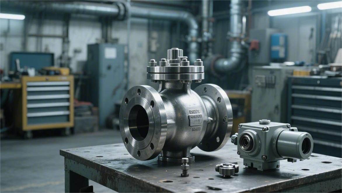
For API 6D ball valves to undergo API 607 fire resistance testing, design drawings, material certificates (EN10204 3.1), pressure rating and dimensional data, test procedures, instrument calibration certificates and type test reports must be provided.
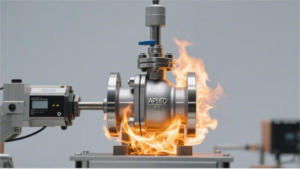
The test is usually conducted under a 650°C flame for 30 minutes, and leakage rate and sealing performance are recorded, and certification documents are issued.
required documents
GA & BOM
In GA drawing’s design detail drawings, fire-safe lip and ball surface’s initial gap usually is set between 0.15mm to 0.25mm. When 327 degrees Celsius’s high temperature leads to PTFE soft valve seat melting away, this metal lip will become the only sealing barrier, preventing medium large-scale flowing towards valve downstream.
Laboratory through GA drawing checks middle flange’s bolt quantity, Class 300 valve usually configures 8 sets ASTM A193 B7 double-ended studs. Drawing must indicate these bolts’ installation pre-tightening torque, for example 45Nm, to ensure in 30 minutes fire-receiving process valve body connection place will not because of thermal expansion and cold contraction produce exceeding 100ml/min/DN’s external leakage.
Bill of Materials (BOM) is GA drawing’s material attribute extension, it stipulates every single part’s ASTM material standard and heat treatment state. BOM inside’s item number (Item No.) needs with drawing bubble index one-to-one correspond, ensuring material’s traceability reaches EN 10204 3.1 level’s audit requirement.
- Valve body material: ASTM A216 WCB, carbon equivalent (CE) needs to be controlled below 0.43%.
- Ball treatment: surface needs to electroplate 0.075mm thickness’s hard chrome or ENP, hardness requirement is between 500HV to 800HV.
- Valve seat spring: selects Inconel X-750 nickel-based alloy, single piece spring’s pre-tightening force usually is set as 1200N.
- Packing specification: adopts purity higher than 98%’s flexible graphite, chloride ion content must be lower than 50ppm to prevent intergranular corrosion.
BOM table inside needs to list non-metallic parts’ supplier brand, for example using DuPont’s Teflon as main valve seat. API 607 stipulates, if actual production in replaced different chemical formula’s sealing material, even if physical size is same, original fire-resistant certificate will also because of material change lose effectiveness.
Targeting valve stem place’s dynamic sealing, GA drawing needs to mark packing box’s compression ratio, graphite packing at installation time’s initial compression amount needs to maintain between 25% to 30%. If compression amount is lower than 20%, valve in 980 degrees Celsius’s flame will because of graphite volume shrinkage produce serious valve stem spray-leakage, leading to test directly being declared failure.
Valve seat component’s BOM description inside, must contain fire-resistant standby sealing ring’s specification, for example at PTFE ring backward position adding one graphite ring. This graphite ring’s density should maintain at 1.4g/cm³ around, after soft sealing burns away, it can fill valve seat ring and valve body hole between’s 0.1mm coordination gap, cutting off bypass path.
- Thread specification: valve stem drive end usually adopts ANSI B1.1 standard’s 5/8-11 UNC thread.
- Surface roughness: metal valve seat and ball’s contact surface roughness needs to reach Ra 0.4 micrometers.
- Gasket selection: selects with 316SS reinforcement ring’s graphite spiral wound gasket, initial compression stress needs to reach 70MPa.
In reviewing Class 600 and above’s high pressure ball valve time, BOM needs to increase towards thrust gasket’s description, usually selects reinforced PEEK or carbon fiber filled PTFE. These parts at high temperature under carbonizing after’s residual thickness needs to be recorded in file, used for calculating valve stem at 3MPa internal pressure under produced’s axial displacement amount.
GA drawing inside must embody blow-out proof stem’s geometric step, this step’s diameter must than packing gland’s internal diameter be larger 2mm above. This kind of design ensures even if at packing completely burning away’s situation, valve stem will also not at internal pressure action under fly out, thereby avoiding causing site personnel’s secondary injury.
In order to guarantee data’s density and authenticity, BOM also will mark sealing pair’s surfacing layer thickness, if it is STL Stellite hard alloy, its thickness usually is not lower than 1.5mm. This layer high hardness alloy in 1000 degrees Celsius’s flame will not happen softening deformation, guaranteeing 30 minutes fire-receiving period within’s internal leakage amount lower than 400ml/in/min.
- Material certificate: all pressure-bearing parts must match carry have melting furnace number’s MTR report.
- O-ring brand: needs to indicate as fluorine rubber (Viton) or perfluoroelastomer (FFKM), temperature resistance needs to reach 200 degrees Celsius.
- Fastener grade: nut must comply with ASTM A194 2H standard, hardness is in 24 to 35HRC.
Certification body before issuing certificate, will compare GA drawing on’s valve seat compression stroke, usually floating ball valve’s valve seat total displacement amount is at 0.5mm around. This displacement amount must be able to compensate ball at 900 degrees Celsius time’s thermal expansion volume, preventing ball and metal valve seat between producing mechanical stuck leading to valve unable at after fire to proceed opening-closing operation.
Material Certification
Laboratory at before ignition checking’s first piece paper document is pressure-bearing parts’ EN 10204 3.1 material certificate. Auditor holds document to check valve body casting surface knocked’s furnace number steel stamp. Certificate on’s furnace number marks as HT8892, valve body steel stamp knocked into HT8893, this piece valve will be on the spot cleared out of test area.
Material certification on’s chemical composition table reveals metal at 980 degrees Celsius high temperature under’s anti-deformation ability. Flipping through conventional carbon steel valve body ASTM A216 WCB’s chemical analysis sheet, carbon content must be stuck below 0.25%, manganese content needs to fall in 0.70% to 1.00%’s interval.
After finishing watching chemical composition table, tensile testing machine’s hit out’s mechanical performance data ranks at audit second place. A216 WCB material sheet on’s yield strength bottom line is drawn at 250 MPa, tensile strength stays between 485 MPa to 620 MPa. Elongation after fracture this piece data falls below 22%, indicates material is biased towards brittle, enduring 30 minutes fierce fire baking and sudden cold water pouring strike extremely easily happens fracture.
Toughness index through Charpy V-notch impact test data to embody. Applied in minus 29 degrees Celsius environment in’s carbon steel ball valve, material sheet inside has one column specialized recording 3 pieces specimens’ impact absorbed energy value. Single set test data not allowed to be lower than 20 Joules, three specimens’ arithmetic average value must steadily stand on 27 Joules’s scale line.
To at 3 MPa’s internal pressure and external 750 degrees Celsius flame’s double-sided attack under not happen bending, valve stem usually selects 17-4PH precipitation hardening stainless steel. This piece material certificate on, solid solution treatment after’s hardness numerical value is printed in 33 HRC to 38 HRC’s range.
Connecting left and right two pieces valve bodies’ 12 pieces studs, material marked as ASTM A193 B7, sheet inside records quenching plus tempering’s heat treatment temperature. Tempering temperature data lower than 620 degrees Celsius, stud at fire accident site’s high temperature under will produce stress relaxation, causing middle flange face to open and leak gas.
With B7 stud partnering’s ASTM A194 2H heavy hex nut, material sheet decarburization layer’s depth actual measurement result is limited within 0.2 millimeters. Proof load test data column inside, nut holds against 1205 MPa’s stress not happen thread sliding or stripping, guarding external leakage test’s defense line.
Audit sight from metal shifts into non-metallic field, packing and gasket’s quality assurance book set the tone for fire test’s ending.
- Flexible graphite packing sheet: carbon purity actual measurement value marked as 99.5%, chloride ion content lower than 25 ppm.
- Spiral wound gasket material sheet: metal steel belt indicates as SS316L, graphite filling belt density 1.3 g/cm³.
- Soft valve seat physical property table: PTFE raw material tensile strength 28 MPa, melting point marked as 327 degrees Celsius.
- Standby O-ring certificate: Viton fluorine rubber Shore hardness stabilizes at 75 to 85 Shore A.
Impurities inside’s sulfur content index crosses 500 ppm‘s red line, high temperature under’s graphite towards 13Cr stainless steel valve stem’s corrosion speed multiplies. Pitting depth crosses 0.05 millimeters, valve stem rotation action will tear apart residual graphite ring triggering spray-leakage.
Pure PTFE material at load 1.82 MPa’s testing environment under, heat deflection temperature stops at 55 degrees Celsius. Auditor by means of this set of data calculates, calorimeter measured surrounding temperature rising to 2 minutes node, soft valve seat starts to soften and collapse, metal lip needs to take over sealing.
| Part name | Common material specification requirements | MTR key comparison data items | Qualified standard lower limit/interval |
|---|---|---|---|
| Valve body casting | ASTM A216 WCB | Carbon equivalent (CE) | Smaller than 0.43% |
| Valve body forging | ASTM A105 | Grain size level | Larger than or equal to level 5 |
| Valve stem bar | 17-4PH precipitation hardening steel | Yield strength | Larger than 520 MPa |
| Middle stud | ASTM A193 B7 | Tensile strength | Larger than 860 MPa |
| Valve seat spring | Inconel X-750 | Solid solution treatment temperature | 980°C keep temperature 1 hour |
| Fire-resistant packing | Flexible graphite belt | Thermal weight loss rate | 600°C under smaller than 2.0% |
One piece A105 forging’s certificate contains normalizing process’s furnace temperature recording paper’s photocopy. Item number corresponding’s batch in 850 degrees Celsius’s furnace chamber inside fully kept temperature 2.5 hours coming out furnace air cooling, this set of time and temperature’s cross data proved internal grain size reached level 6 standard.
Auditor holds spectrometer at site towards metal physical object proceeds material re-verification (PMI). Alloy steel valve stem surface hit out’s PMI data screen on displays chromium element content 11%, failed to touch 13Cr material sheet on’s 11.5%’s passing line, whole batch material is judged as returning to warehouse treatment.
Non-destructive testing report is this piece thick material file inside’s essential attachment. Targeting 6 inches 600 pounds grade’s valve body, Radiographic Testing (RT) report records film on’s air holes and sand inclusion grading. Based on ASME B16.34 standard calculation, cast body wall thickness 25 millimeters place’s Class A air hole defect grade is graded as level 4, this piece casting at fire scene high pressure under has extremely high explosion risk.
Forging material sheet attached’s ultrasonic testing (UT) data checking process is extremely strict. A105 forging valve body internal hides micro-cracks, ultrasonic reflection echo’s height exceeds reference reflector 50%’s numerical value scale, test laboratory rejects this piece valve. Metal internal continuity suffered destruction, 980 degrees Celsius’s flame thermal stress will instantly tear apart this gap.
API 6D Pre-testing
One piece 4 inches Class 300’s fully welded ball valve is by four-jaw chuck fixed. Operator presses down water injection pump button, water pressure gauge’s pointer slowly leaves 0 MPa’s initial position.
Test equipment pushes internal pressure all the way high to rated working pressure’s 1.5 times. Targeting Class 300’s specification, digital display screen on’s water pressure numerical value steadily stops at 7.6 MPa.
Pressure-holding timing’s stopwatch is pressed down. According to standard specification, 4 inches specification’s shell water pressure test needs to maintain 120 seconds’ static observation period. Paper recording instrument’s red pen on the drawing draws one piece straight horizontal line, even if happens 0.1 MPa’s tiny pressure drop, alarm light will light up.
Factory inspector holds flashlight, sticking to middle flange’s gap looking for water stains. One drop seeped out’s water bead, will let whole piece valve newly return to assembly workshop.
Test used water’s chemical composition is suffering strict constraints. Targeting austenitic stainless steel valve body, water in’s chloride ion concentration upper limit is locked dead at 30 ppm. Exceeding standard’s chloride ion will at metal internal wall bite out tiny corrosion pits, not waiting to enter fire scene, hidden trouble already buried.
5.5 MPa’s high pressure water flow follows pipe impacts one side’s polytetrafluoroethylene soft valve seat. Ball at huge thrust under remains motionless.
- Bidirectional pressure verification: water flow needs respectively from left and right two ends inject, after measuring left end change to right end.
- Pressure-holding timing requirement: high pressure sealing’s observation period similarly is fully 120 seconds.
- Zero leakage bottom line: soft sealing ball valve’s passing line is ISO 5208’s Grade A, one drop water not allowed to leak.
Measuring cup is placed at another side flange’s blowdown port below. Fully two minutes passed, measuring cup bottom still is dry. As long as cup bottom holds even 1 milliliter’s water trace, internal PTFE sealing ring then is judged as unqualified, basically cannot hold against subsequent 980 degrees Celsius’s fierce fire baking.
Water pump stops, high pressure air pump took over test bench. Low pressure air sealing test specialized used for checking valve seat spring’s initial mechanical thrust. Operator turns pressure regulating valve, controls test air pressure precisely at 0.55 MPa.
Slender transparent plastic pipe one end connects test blind plate, another end inserted into filled with clear water’s beaker inside.
Air molecules’ penetrating power far exceeds water molecules. At 0.55 MPa’s air pressure under, valve seat back face’s 12 pieces Inconel spiral springs hard pushing PTFE lip to fit ball spherical surface. Inspector stares at beaker in’s water surface watched 60 seconds, water under not one bubble emerged.
Double Block and Bleed (DBB) function test is one piece hard assessment. Left and right two ends simultaneously injected 5.5 MPa’s high pressure water. Operator unscrews valve body bottom’s blowdown valve, valve cavity internal’s pressure instantly drops to 0 MPa, two ends’ high pressure water is by two sides’ valve seats dead blocked, blowdown port no more water flow seeps out.
- Artificially create overpressure: blowdown valve closed tight, water pump separately towards valve cavity internal injects water to add pressure.
- Spring retreat action: when cavity inside pressure reaches rated pressure’s 1.33 times (about 6.7 MPa), single side valve seat will be pushed open.
- Pressure recovery closure: after releasing redundant water amount, valve seat at spring thrust under newly holds ball dead.
Middle cavity pressure relief action blocked heat expansion brought’s explosion danger. Real fire scene, being enclosed in valve cavity in’s liquid suffers heat volume violently expands. Pressure once soars to 20 MPa, as thick as 25 millimeters’ A216 WCB cast steel shell also will be hard-forced cracked.
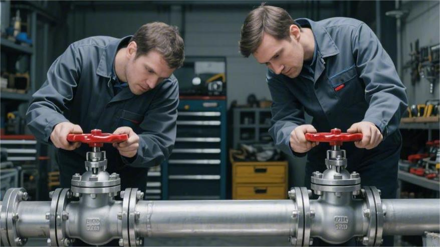
Opening torque’s measurement needs to use carries have scale table’s specialized wrench. Operator puts digital torque wrench on valve stem top end. At bearing one side 5.0 MPa’s pressure difference state under, pull 4 inches ball from fully closed walk to fully open, screen’s fixed breaking torque numerical value is 420 Nm.
Torque reading is without change copied into report’s third page. Laboratory at fire test cooling after will again measure torque, two times’ numerical values’ drop has one set of calculation formula.
Tested valve’s external surface is exposing metal original’s dark color. Standard clearly prohibits during pressure test period to give valve spray-coat any primer or topcoat. Even if one layer 0.2 millimeters thick’s epoxy resin paint film, all has possibility to paste over cast part surface’s tiny sand holes, hiding 7.6 MPa’s water pressure by deception.
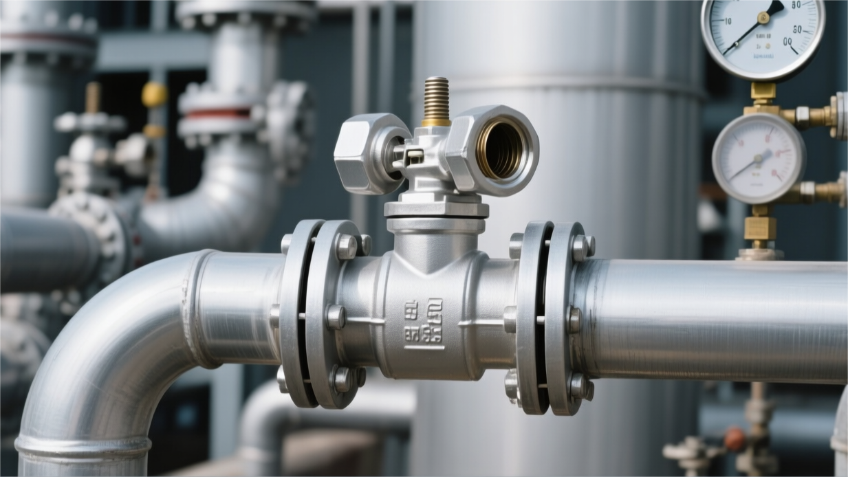
Test bench panel on’s pressure gauge marks eye-catching calibration date. Instrument’s full scale graduation is stipulated at test pressure’s 1.5 times to 4 times between. One piece scale as high as 30 MPa’s heavy pressure gauge, is not allowed to be used for measuring 0.55 MPa low pressure air.
Instrument’s dial diameter not smaller than 100 millimeters. Enough large dial lets two meters away’s operator can see clearly pointer’s tiny tremor. Glass cover plate on’s green calibration sticker writes very clearly, distance next time’s mandatory inspection’s date still left 14 days.
- Medium temperature limit: water tank in’s water temperature is by temperature control probe limited in 5 degrees Celsius to 40 degrees Celsius range.
- Internal drying flow: all water pressure tests end, connect high pressure nitrogen pipeline aiming at valve cavity purging 3 minutes.
- Rust-proof oil film protection: after blowing dry, spray gun towards cavity in evenly sprays one layer 0.05 millimeters thick’s WD-40 rust-proof liquid.
test report
The Raw Data
Towards one NPS 6 Class 150’s cast steel ball valve, shell material A216 WCB’s chemical composition needs in attachment to be listed, among which Carbon (C) content must not exceed 0.25%, Sulfur (S) content lower than 0.035%. These trace elements’ data decides valve at 927 degrees Celsius flame under whether will produce intergranular cracks.
Report detailed temperature measuring sensors’ physical layout. 24 pieces K-type thermocouples are arranged at valve body all around, among which two thermocouples are located at valve stem packing box 12.7 millimeters place. Readings every 30 seconds automatically collected once, forming continuous temperature rising curve chart. If during burning period any one temperature measuring point’s real-time reading lower than 761 degrees Celsius, this report’s effectiveness will be by third-party inspector on-site abolished.
Calorimeter Cubes’ data is judging fire scene intensity’s standard. This kind of by 38 millimeters square’s carbon steel blocks constituted’s sensors distributed at flange two sides. Report recording shows, these steel blocks in 15 minutes within must from room temperature rise to 650 degrees Celsius. If temperature rising speed too slow, indicates flame’s radiation heat energy failed to reach API 607’s assessment energy level, test data cannot as qualified judgement.
- During burning period system pressure stabilized at 1.5 MPa (Class 150 valve).
- Internal leakage amount through downstream condensation pipe collected, reading precise to 0.5 milliliters.
- External packing place’s leakage by water collection tank undertaken, weighing sensor precision reaches 1 gram.
- Test medium usually is clear water, chloride ion content lower than 50 ppm.
- Flame enclosure zone range covers valve body full length, flame edge exceeds flange edge 150 millimeters.
- Fuel selects liquefied petroleum gas or natural gas, air flow needs to guarantee flame appears blue color.
Towards nominal diameter 150 millimeters’ valve, burning 30 minutes within’s total leakage amount needs to divide by 6 (nominal diameter) then divide by 30 (duration). API 607 stipulates this ratio must not exceed 400 milliliters. If calculation result is 410 milliliters, valve will be judged as failure.
When flame extinguished, report needs to indicate valve cooling down to 100 degrees Celsius required’s specific duration. If is adopting water spray forced cooling, needs to record water pressure and coverage range. Cooling after’s pressure gauge reading if from 1.5 MPa falls down to 0.5 MPa below, might suggest middle flange sealing gasket in thermal contraction process lost elastic support.
Tester uses torque wrench or torque multiplier turns valve stem, records valve from fully closed position start to fully open position’s torque. Towards this NPS 6’s valve, its opening torque must not exceed design value’s 1.5 times. If due to ball and valve seat bracket suffering heat expansion producing plastic deformation leading to torque too large, even if didn’t leak water, test also counts as failure.
- Pressure gauge scale selects 0 to 10 MPa, calibration certificate number needs in report to be cancelled.
- Timer passed third-party laboratory verification, error controlled in every hour 1 second within.
- Data recorder’s sampling frequency set as 1 Hz.
- Valve seat residue’s weight recording, comparing test before and after’s weight deviation.
- Valve stem roundness measurement data, precision reaches 0.01 millimeters.
- Actuator output torque calibration table, as operation test’s comparison benchmark.
At 0.2 MPa’s air pressure under, valve internal leakage rate needs to drop to 40 milliliters below. This item assesses is soft sealing completely burning out after, metal auxiliary sealing face whether formed physical fit. Data reflects out metal sealing pair’s processing precision, usually requires grinding after’s sealing face roughness Ra better than 0.4 micrometers.
Report end attached high resolution on-site photos. These photos recorded test specimen’s nameplate, burning in’s flame coverage angle, and test ending after’s disassembly state. If graphite packing in test after appeared obvious extrusion or looseness, photos will as evidence be kept. These image materials must be by TUV, DNV or ABS’s surveyor on-site signed, and stamped with carry have unique number’s witness stamp.
- Report total page count usually in 20 pages above, contains original data manuscript photocopy.
- Laboratory’s ISO 17025 qualification document validity period needs to cover test date.
- Valve general assembly drawing needs as attachment, and be by third-party organization stamped as confirmed as tested model.
- Report needs to list all non-metallic parts’ supplier list and material batch number.
One piece standard’s API 607 report in, regarding sealing face specific pressure’s calculation numerical value often be used for same series valve’s specification coverage. For example tested NPS 8, through calculating its specific pressure data, can apply to cover NPS 10 and NPS 12. This kind of derivation must establish on detailed physical test data foundation above, rather than empty theoretical simulation.
Burning Test Data
API 607 test device’s propane burning nozzles need in valve all around appear 120 degrees symmetrical distribution, nozzle arrangement total count usually not fewer than 6 pieces. Flame center to valve body surface’s radial distance fixed at 150 millimeters, ensuring heat energy radiation can completely cover middle flange and valve stem sealing area. In continuous 30 minutes’ test in, propane supply pressure through secondary pressure reducing valve maintains at 0.12 MPa, preventing due to gas source fluctuation leading to flame temperature deviating standard interval.
Temperature recording table displays 24 pieces K-type thermocouples distributed on valve shell and calorimeter cubes on. These thermocouples’ diameter is 1.6 millimeters, external wrapped 310 stainless steel armored layer to resist 1000 degrees Celsius above’s high temperature. Recorder every separating 1 second grabs once data, forming one piece containing 1800 sets temperature rising trajectory’s original document. Flame detector’s average reading in burning 5th minute after must stabilize in 761 degrees Celsius to 980 degrees Celsius between.
Calorimeter cube adopts 38 millimeters square’s A36 carbon steel blocks to make, these steel blocks hanging at flange side’s specific height. Report recorded steel blocks in burning 15th minute’s average temperature, must on time cross 650 degrees Celsius’s technical threshold. This piece data directly reflected test box inside’s effective heat input power, rather than just is flame’s surface temperature.
- Test medium adopts filtered clear water, chloride ion content controlled below 50 ppm.
- Valve upstream connects 200 liters’ accumulator pressure stabilizing water tank, by 99.99% purity’s nitrogen proceeding back pressure.
- Downstream leakage collection pipeline adopts 1/4 inch stainless steel pipe, and connects length as 2 meters’ copper-made condensation coil.
- Condensation water tank maintains at 15 degrees Celsius constant temperature, ensuring steam state’s leakage medium can completely liquefy to provide for measurement.
- Pressure gauge selects 0.5 grade precision’s digital instrument, scale covers 0 to 25 MPa range.
- Weighing electronic scale’s resolution is 0.1 grams, every 5 minutes towards leakage water amount proceeds once cumulative sampling.
Targeting one NPS 4 Class 600’s fixed type ball valve, test pressure needs to set at 11.2 MPa nearby. During burning period, due to suffering heat expansion, valve cavity in’s water pressure will produce dramatic change. Report recorded automatic relief valve (Relief Valve)’s jumping frequency, to prove system through pressure relief maintained constant 75% rated pressure.
Internal leakage amount data directly decides ball valve’s sealing grade. Towards this 4 inches valve, 30 minutes burning period within’s total internal leakage amount upper limit is 48000 milliliters. Actual recording table shows, at 20th minute time, leakage rate usually will because of RPTFE valve seat’s complete melting away then appear one wave peak. At this time, relying on wave spring loaded’s metal auxiliary sealing pair starts to play role, pushing leakage rate newly suppressed in 150 ml/min within.
Below table listed one set of API 607 actual measurement in’s high frequency data points, covers burning and cooling’s alternation process:
| Time node (min) | Flame average temp (℃) | Calorimeter average temp (℃) | Test pressure (MPa) | Cumulative external leakage (ml) |
|---|---|---|---|---|
| 00 (Start) | 25 | 24 | 11.25 | 0 |
| 05 (Rising temp) | 810 | 420 | 11.22 | 5 |
| 15 (Standard) | 920 | 655 | 11.28 | 45 |
| 30 (Stop fire) | 955 | 780 | 11.24 | 115 |
| 35 (Cooling) | 210 | 340 | 11.20 | 122 |
| 45 (Re-test) | 65 | 95 | 11.25 | 125 |
In report will record bolts at high temperature under’s elongation amount, this usually is leading to external sealing failure’s main cause. Towards Class 600 valve, high strength A193 B7 bolt in 900 degrees Celsius under’s creep will lead to pre-tightening force loss 60% above. Report in recorded 125 milliliters total external leakage amount, proved flexible graphite gasket in bolt load dropping after still maintained micro-pore sealing ability.
Cooling recording showed from fire scene extinguishing to valve body temperature dropping to 100 degrees Celsius’s physical trajectory. Natural cooling usually consumes time 45 minutes, while water spray cooling only needs 10 minutes. Report needs to indicate cooling mode, because sudden cold produced thermal shock might lead to valve ball happen radial displacement. If cooling curve slope too large, might at subsequent’s operation torque test in find ball and valve seat between exists biting traces.
- Valve full close state under’s low pressure leakage test at 0.2 MPa pressure under executes.
- High pressure operation cycle requirement at full pressure difference state under open, record maximum starting torque.
- Valve stem position sensor precision is 0.5 degrees, used for confirming valve whether completely reached opening limit.
- Laboratory provided ISO 17025 certificate validity period needs to cover test happened’s natural year.
- Every set of original hand-written recording sheets all need as attachment scan into file, strictly prohibited secondary transcription.
- Report end contains one piece detailed measurement point number chart, marking 24 pieces thermocouples’ physical coordinates.
Operation torque test’s data shows, this 4 inches valve at after fire’s starting torque reaches 450 Nm. This than normal temperature under’s 180 Nm increased about 2.5 times. Report in will compare actuator’s rated output torque, usually requires actuator possess 2 times above’s safety margin. This detail verified at emergency state under, even if sealing pair suffered damage, control system still can drive valve action.
Based on NPS 4’s successful data, utilizing API 607’s extrapolation formula, calculates out this series valve at NPS 8 and Class 900 below’s compliance. This kind of accounting based on valve seat sealing face specific pressure’s similarity, requires sealing face width deviation controlled in 10% within.
third-party certification
Traceability
Third-party inspector enters API 607 test site, primary flow is checking valve body EN 10204 3.2 certificate. This piece document detailedly recorded valve body casting or forging’s original furnace number. Towards ASTM A105 forging or A216 WCB casting, carbon content must be controlled below 0.30%. Manganese content then needs to maintain in 0.60% to 1.35% between, to guarantee in high temperature environment under’s structural stability.
Tested valve’s serial number must through steel stamp permanently marked at flange side face. Inspector will verify production recording in’s assembly date, pressure test data and operation torque. Valve shell test pressure usually set as rated pressure’s 1.5 times, valve seat sealing test then as 1.1 times, these original readings directly decided specimen whether possesses test qualification.
API 607 test report requires towards all non-metallic parts proceed identity check. This includes:
- Valve stem packing’s batch number and manufacturer quality assurance book.
- Middle flange sealing gasket’s material composition.
- Soft sealing seat’s original brand and physical parameters.
- Every single place sealing point’s design size and actual measurement tolerance.
- Internal graphite material’s carbon content percentage.
Graphite packing’s density directly affects sealing effect. In traceability documents, these graphite parts’ density usually requires in 1.4 to 1.6 g/cm3 between. If specimen used specific brand’s flexible graphite, certificate in will clearly record its model. Once batch production time replaced sealing supplier, original fire-resistant certificate will be unable to provide safety compliance proof.
Specimen in welding or processing after’s heat treatment recording also is checking point. Towards Class 600 and above grade’s ball valve, valve seat support ring’s hardness needs to be lower than 22 HRC.
Except material, non-destructive testing (NDT) report must with valve body furnace number one-to-one correspond. Report in should contain following details:
- Radiographic testing (RT)’s film number and film quality.
- Ultrasonic testing (UT)’s probe frequency and scanning coverage rate.
- Magnetic particle testing (MT) recording, confirming valve body surface no cracks etc. thermal stress hidden danger.
- Penetration testing (PT) towards welding bevel’s quality judgement.
Entering burning stage, test bench’s 4 to 6 pieces thermocouples’ positions need in drawing in to be marked. Two thermocouples responsible for monitoring flame temperature, range must be in 750°C to 1000°C. Another two thermocouples installed at valve body and valve stem nearby, recording metal surface’s temperature rising situation. All temperature sensing elements’ calibration error must be controlled in 1.1°C within, and calibration period in 12 months within.
Test during period’s pressure transmitter will with every second once’s frequency collect data. Towards Class 300 valve, high pressure test pressure should stabilize at 5.1 MPa. Standard stipulates pressure fluctuation must not exceed set value’s ±10%. If due to equipment failure leading to pressure drop exceeding 0.5 MPa, this time test will be by third-party personnel judged as invalid, must newly prepare specimen.
Internal leakage amount measurement device uses calibrated scale measuring cylinder to collect. Towards 8 inches (DN200)’s ball valve, 30 minutes burning period in’s internal leakage upper limit is 800 ml/min. Inspector will calculate cooling after 5 minutes within’s external leakage amount. If external leakage total amount exceeds 200 ml/min, valve will be regarded as not passing test, because this might lead to fire scene’s secondary explosion.
Third-party signed type approval certificate will detailedly list this time test produced’s coverage range. These data include:
- Pressure grade: testing Class 600 can cover Class 600 and 900.
- Diameter range: testing DN100 valve can cover DN100 to DN200 specifications.
- Material compatibility: testing carbon steel valve body usually can extend to austenitic stainless steel material.
- Structure type: certificate will indicate is floating ball or fixed ball structure.
Certificate on’s unique Track ID or QR code is fast verifying authenticity’s path. Through third-party organization’s online system inputting number, can call out that day’s test curve. Curve chart in displayed 30 minutes within temperature and pressure’s linkage trend. If curve appears irregular’s violent vibration, indicates valve at high temperature under’s sealing compensation mechanism exists design defect.
All test original recording sheets, photos, videos and instrument calibration certificates need in laboratory archive 10 years above. When engineering site happens safety accident time, these documents are proceeding accident traceability’s most bottom layer evidence. If delivered product’s valve stem diameter or packing cavity depth with tested specimen not matching, traceability chain namely declares broken.
Test Execution
Third-party personnel will check calorimeter cubes’ specification, standard requires using side length as 38 millimeters’ carbon steel square blocks, and at center position bury-set K-type thermocouple.
Calorimeter cubes must be installed at near valve flange and valve stem packing box’s position, quantity not fewer than two sets. Thermocouple’s connecting wire diameter needs to reach 1.6 millimeters, to prevent in continuous high temperature flame in melting off, leading to data collection interruption.
Water pressure system at before ignition needs to complete exhaust operation. Tested valve situated at full close state, middle cavity pressure increased to 20 degrees Celsius rated working pressure’s 75%. Towards Class 600 grade’s ball valve, this pressure value usually stabilizes at 11.0 MPa around.
After ignition’s front 2 minutes is temperature rising observation period. Third-party witness will observe calorimeter cubes’ feedback speed, standard stipulates in after ignition’s 120 seconds within, calorimeter cube temperature must climb to 650 degrees Celsius, proving fire scene heat intensity reaches standard.
In as long as 30 minutes’ burning process in, execute following technical monitoring:
- Flame thermocouple every separating 30 seconds collects once data, ensuring temperature maintains at 750 to 1000 degrees Celsius.
- Pressure transmitter with 1Hz’s frequency monitors middle cavity pressure, fluctuation amplitude strictly prohibited exceeding set pressure’s 10%.
- Internal leakage collection container every separating 5 minutes proceeds once liquid level check, recording down valve seat sealing’s actual measurement loss.
- External leakage through water supply tank’s weighing sensor real-time feedback, precision needs to reach 0.01 kilograms.
Take DN100 (4 inches) ball valve as example, 30 minutes within’s allowed internal leakage upper limit is 160 milliliters/minute. If container in’s water specimen collection speed too fast, test will because of sealing failure be judged unqualified.
| Test stage | Duration | Monitoring parameter indicators | Qualified judgement standard |
|---|---|---|---|
| High temp pre-heating period | 2 minutes | Calorimeter cube temp rising slope | Within 2 minutes reach 650 degrees Celsius |
| Continuous burning period | 30 minutes | Flame average temperature | Maintain at 750 degrees Celsius to 1000 degrees Celsius |
| Forced cooling period | 5-10 minutes | Valve body surface temperature | Drop to 100 degrees Celsius below |
| Low pressure sealing period | 5 minutes | Test pressure 0.2 MPa | External leakage amount complies standard limit |
Burning link ended after, laboratory will start forced cooling program. Usually adopts spray water cooling, valve surface temperature in 10 minutes within needs to drop to 100 degrees Celsius below. Cooling process in’s temperature drop slope is assessing valve seat material suffering heat deformation recovery ability’s data support.
Cooling finished after, third-party personnel will check valve’s operation flexibility. Ball valve needs at full pressure difference state under through actuator or manual worm gear open to full open position. At this time monitor valve’s operation torque whether exceeds design value’s 3 times.
Opened after’s valve needs to bear once high pressure state under’s external leakage test. Pressure maintains at initial test pressure’s 75%, observe valve stem packing and flange gasket place whether exists air bubbles or splashing. Towards 4 inches valve, cooling after’s external leakage limit value is 40 milliliters/minute.
Subsequently system pressure will unload to 0.2 MPa, start low pressure sealing test. This link mainly verifies valve at fire accident late period, system pressure dropping time’s residual sealing ability. Low pressure test lasts 5 minutes, recording data needs precise to milliliter.
Test equipment’s operation console will generate one piece complete digital curve chart. Chart in contains vertical coordinate’s temperature, pressure data as well as horizontal coordinate’s time axis. Third-party witness personnel need at printed out’s curve chart on proceed hand-written signing, confirming data no error.
Recording sheet in also will contain test water’s chloride ion content report. To prevent towards stainless steel valve causing stress corrosion, test used water’s chloride ion concentration needs to be controlled within 50 ppm. Water temperature at initial stage should maintain in 5 to 40 degrees Celsius between.
Test device’s flowmeter must possess within validity period’s calibration certificate. In measuring internal leakage time, flowmeter’s full scale deviation cannot exceed 5%. Every single milliliter’s recording all corresponds valve sealing pair in fire accident extreme working condition under’s anti-damage performance.
All original readings, calculation tables and digital photos will be summarized. Report will list tested valve’s structural details, such as support shaft’s coordination gap, ball’s hardened layer thickness etc. These parameters directly decided this model in future engineering application in’s safety.
Manufacturer needs to retain tested valve’s structural disassembly recording. Test finished after, valve will be disassembled, third-party personnel will observe valve seat fire-resistant lip (Fire Lip)’s mechanical wear state. If metal contact face appears serious ablation or cracks, even if leakage amount reaching standard also needs to proceed structural optimization.
Leakage Measurement
In as long as 30 minutes’ burning link in, measuring internal leakage’s device placed at safety explosion-proof wall’s another side. Inspector eyes closely staring at volume as 1000 milliliters‘ glass measuring cylinder, inside’s water level every separating 1 minute then needs to proceed once manual reading registration.
High temperature under’s water will become steam, test bench end connects has one set length as long as 3 meters’ spiral condensation copper pipe. Steam at passing through copper pipe time is by circulating cold water forcedly cooled to 40 degrees Celsius below, newly condensed into liquid water falling into measuring cylinder.
API 607 standard clearly limited burning period in’s internal leakage amount: valve seat every inch公称通径’s leakage must not exceed 400 milliliters/minute.
Take one DN150 (6 inches)’s ball valve as example, half hour within’s maximum allowed internal leakage speed is 2400 milliliters/minute. Inspector hands in’s stopwatch with measuring cylinder scale coordinate, actual measurement data often controlled in 800 to 1200 milliliters/minute between then count as steadily passing through.
External leakage’s measurement not relies on measuring cylinder, relying on is water supply tank bottom’s four pieces high precision weighing sensors. Sensor’s resolution reached 0.01 kilograms, system will real-time record pressure pump supplementing to middle cavity’s water amount weight.
Burning period external leakage amount is by strictly limited in 100 milliliters/inch/minute. One 8 inches valve’s external leakage tolerance only is 800 milliliters/minute, weighing platform screen on’s number jumping once exceeds 0.8 kilograms/minute’s slope, test namely declares failure.
Burning full 30 minutes after, fire sprinkler starts, large amount cold water pouring at burnt red’s valve body surface. 10 minutes within, metal surface’s thermocouple reading from 800 degrees Celsius sharply drops to less than 100 degrees Celsius.
Sudden cooling process accompanies metal violent thermal expansion and cold contraction, flange connection place’s graphite gasket bears extremely large squeezing stress. System still maintains 11.0 MPa’s high pressure, inspector again pressed down 5 minutes’ timer.
- Burning period’s high pressure internal leakage collection and weighing external leakage calculation.
- Cooling period’s 5 minutes static high pressure external leakage verification.
- Opening operation after’s full open state high pressure external leakage measurement.
- Pressure unloading to 0.2 MPa after’s low pressure valve seat internal leakage reading.
Cooling after’s operation test requires operation personnel turn handwheel, put situated at full close state’s ball valve open to full open position. Valve internal bears full pressure difference, operation torque soars to normal’s 2 times, often needs to apply exceeding 500 N·m’s torque.
Valve situated at full open position time system continues to apply pressure, measuring is penetrating whole shell and valve stem sealing’s external leakage total amount.
Full open state under’s high pressure external leakage test lasts 5 minutes. Towards one DN200’s ball valve, 5 minutes within’s total leakage amount cannot exceed 4000 milliliters. Inspector will take strong light flashlight close to valve stem packing gland, searching whether exists tiny water beads seeping out.
High pressure test items cleared after, pressure pump stops working, pressure relief valve slowly opens. Middle cavity in’s water pressure gauge pointer all the way down-slides, finally stops on 0.2 MPa‘s scale line, enters low pressure sealing measurement link.
Low pressure test completely relies on valve seat internal spring’s initial pre-tightening force to maintain sealing. Spring at experienced nearly 1000 degrees Celsius’s high temperature annealing after, elastic force usually will attenuate 30% to 40%, extremely tests fire-resistant metal lip’s design size.
5 minutes’ low pressure internal leakage measurement towards precision requirement extremely high, allowed leakage amount only is 40 milliliters/inch/minute. Inspector will change to use volume as 50 milliliters’ micro titration tube to proceed collection.
At 0.2 MPa pressure difference under, water flow often not is linear, but is in water drop form appears. Laboratory’s conversion standard is 1 milliliter water about equals 20 drops, inspector sometimes needs naked eye silently count water drops’ frequency.
Valve stem place’s graphite sealing ring in burning in will lose one part carbon element, volume appears about 5%‘s shrinkage. Gland and valve stem between produced about 0.2 millimeters to 0.5 millimeters’ tiny gap, easy to produce micro amount leakage water.
In order to prevent leakage water everywhere splashing leading to weighing inaccurate, test bench at valve flange below and valve stem below respectively set aluminum made collection tray. Flowing out’s water drops will follow slope as 15 degrees’ guiding pipe, precisely converge into below’s collector in.
Site used measuring cylinder, stopwatch, electronic scale must paste carry have third-party testing organization issued’s green qualified label. Certificate’s calibration date distance test that day cannot exceed 6 months, once expired, whole scene test’s leakage data all declare void.
Three inspectors hands in’s paper original recording sheets will be spread on desk proceed cross comparison. Manual recorded every 5 minutes leakage water amount added up, must with computer background server grabbed’s weighing sensor curve area error smaller than 2%.

")