
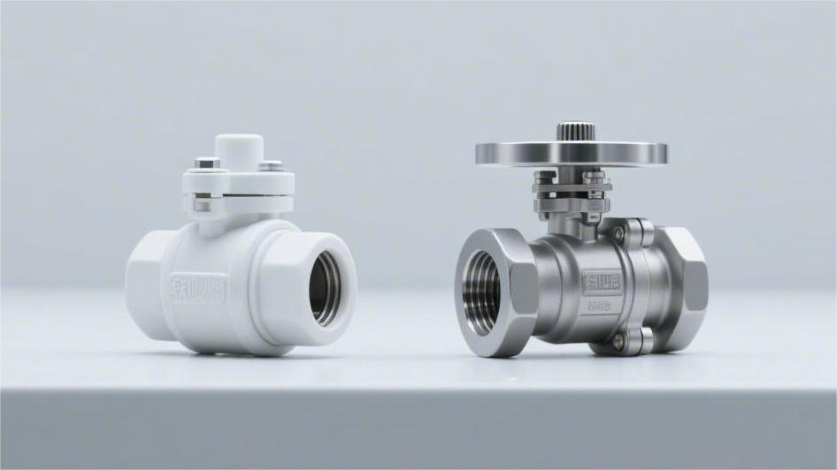
Soft-seated side-entry ball valves (such as PTFE) are suitable for temperatures below 200°C and can achieve Class VI zero leakage, but they have poor wear resistance. The pipeline must be purged before operation to prevent particles from scratching the valve seat.
Metal-seated valves (such as those with tungsten carbide coatings) can withstand high temperatures up to 500°C and are extremely wear-resistant. They are specifically designed for media containing solid impurities, but typically only meet the Class IV standard for micro-leakage.
Temperature Range
The operating temperature of soft-seated side-entry ball valves (PTFE, PEEK, etc.) generally ranges from -40°C to 260°C. Exceeding 260°C will cause polymer materials to soften and undergo permanent plastic deformation.
The coefficient of thermal expansion for soft sealing materials is about 10 times that of metals. Metal hard-seated ball valves have a conventional range of -196°C to 427°C;
If the rear spring is replaced with Inconel 718 and full graphite gaskets are used, the maximum operating temperature can be extended to 538°C or even 815°C. This relies primarily on mechanical springs to real-time compensate for physical displacements caused by thermal expansion and contraction.
Soft Sealing
The molecular chain of pure polytetrafluoroethylene (PTFE) is composed of carbon-fluorine bonds, resulting in a friction coefficient of only 0.04. This extremely low frictional resistance allows the operating torque of an ASME Class 150 6-inch ball valve to be kept under 150 N·m.
When the internal system pressure exceeds the yield strength of the polymer, the material experiences a creep phenomenon. Under an ambient temperature of 20°C and a continuously applied pressure of 15 MPa, a pure PTFE seat will exhibit approximately 4% radial deformation within 48 hours. The ball pushes against the seat under pressure, and exceeding the elastic recovery limit will result in permanent dimensional reduction.
To suppress physical deformation, manufacturers usually dope the base material with 15% to 25% chopped glass fibers or carbon fibers to create reinforced polytetrafluoroethylene (RTFE). After doping, the tensile strength of the material increases from 14 MPa to 25 MPa, and the heat deflection temperature is raised by about 40°C. RTFE containing 25% carbon fiber sees its thermal conductivity increase to 0.45 W/(m·K).
Natural gas pipeline transportation conditions frequently use polyamides (Nylon 12 or Devlon V-API) as seals. The Rockwell hardness of Devlon V-API reaches R112, allowing it to withstand extreme pipeline pressures up to 137 MPa. Its water absorption rate is exceptionally low, with a weight increase of less than 0.1% after soaking in 23°C water for 24 hours.
In high-pressure natural gas systems, gas molecules penetrate the microscopic pores of the polymer. When an emergency pipeline blowdown occurs, and the system pressure drops precipitously from 100 bar to atmospheric pressure in seconds, the expansion stress inside the polymer can reach hundreds of megapascals. Anti-Explosive Decompression (AED) testing requires that the cross-sectional crack length of the material after undergoing a depressurization cycle must not exceed 5% of the total packing thickness.
Polyetheretherketone (PEEK) exhibits extremely high yield strength in harsh chemical environments and high temperatures. Even in a 200°C environment, its tensile strength remains above 50 MPa. PEEK seats typically use a floating design with O-rings paired with Belleville springs, requiring an initial preload equivalent to 1.2 times the projected area of the seat.
In sour gas field environments with high concentrations of hydrogen sulfide (H2S), soft sealing components must comply with the NACE MR0175/ISO 15156 standard. Fluoroelastomer (FKM) O-rings are prone to cross-linking and hardening when exposed to H2S concentrations exceeding 10%; their Shore hardness can surge from 75A to over 90A within 168 hours.
The assembly between the seat insert and the metal support ring utilizes an interference fit process to achieve initial bi-directional sealing. The assembly tolerances are strictly controlled, reflecting as follows:
- The outer diameter of the PTFE insert is typically 0.05 mm to 0.15 mm larger than the inner diameter of the support ring groove.
- The assembly pressure must be maintained between 2 and 5 MPa to avoid microscopic cracks.
- After pressing in, it must rest at room temperature for 24 hours to release residual stresses.
- The surface roughness of the contact face must reach Ra 0.4 microns.
API 607 fire-safe testing requires side-entry ball valves to maintain cutoff capability after being baked by a 750°C to 1000°C flame for 30 minutes. Polymer seats completely burn and vaporize at around 350°C. Driven by pipeline pressure, the ball subsequently moves downstream and presses tightly against the machined step on the metal valve body.
The secondary metal sealing band after the fire must meet strict testing specifications for extremely low leakage rates:
- The contact ring band width between the ball and the secondary metal step is usually 1.5 to 3 mm.
- System water pressure during testing is maintained at 2 MPa.
- The maximum allowable external leakage is 20 milliliters per minute per inch (nominal diameter).
- The low-pressure test pressure post-fire is 0.2 MPa, sustained for 5 minutes.
The friction coefficient of polymer materials exhibits a non-linear increase over time and with changes in system pressure. For a ball valve that has remained closed for an extended period, the starting torque may increase by 30% to 50% compared to its initial value because the polymer plastically embeds into the ball’s microscopic surface. The safety factor for selecting a pneumatic actuator must usually be set at 1.25 to 1.5.
Solid particulates entrained in the pipeline with a diameter greater than 50 microns easily embed into the softer PTFE surface. Under the high-speed scouring of fluids, fine grit will plow scratches 0.1 to 0.5 mm deep into the polymer surface. In gas conditions with a differential pressure of 10 bar, even minuscule scratches can trigger a leak exceeding 500 standard cubic centimeters per minute.
The Double Block and Bleed (DBB) function relies on the self-relieving design of the soft sealing components to prevent abnormal pressure buildup in the middle cavity. The mechanical action of the relief path is as follows:
- When the middle cavity pressure exceeds 1.33 times the pipeline pressure, the spring yields.
- The upstream seat is pushed away from the ball, creating a clearance of approximately 0.5 mm.
- The trapped fluid discharges to the low-pressure side of the pipeline, typically taking less than 2 seconds.
- After depressurization, the spring resets the support ring with a thrust of about 800 N.
Polychlorotrifluoroethylene (PCTFE) is commonly used in cryogenic control segments of LNG receiving terminals. The shrinkage rate of this material at -196°C approaches 2.5%; engineered solutions offset this volume reduction by installing a wave spring at the rear with a pre-compression of 3 to 5 mm. Cryogenic sealing tests require filling with helium gas and detecting with a mass spectrometer, where the leakage rate must be less than 1.0×10^-4 mbar·L/s.
Metal Hard Sealing
The seat base material of metal hard-seated ball valves typically uses ASTM A105 forged steel or F316 stainless steel to cope with ASME Class 900 and higher high-pressure pipelines. To resist fluid erosion, a layer of tungsten carbide coating between 0.15 and 0.3 millimeters thick is applied to the substrate surface via the High-Velocity Oxygen Fuel (HVOF) process.
The spray velocity of the HVOF process reaches 800 meters per second, causing the tungsten carbide particles to impact the metal substrate with extreme kinetic energy, forming a dense coating with a bond strength exceeding 70 MPa. The surface Rockwell hardness of tungsten carbide is typically between 70 and 72 HRC, easily capable of crushing quartz sand or catalyst particles entrained in the fluid.
After spraying is complete, the ball and seat must enter a CNC lapping machine for hours of mate-lapping. Diamond micron powder with a particle size of 3 to 5 microns is mixed into the lapping fluid, ultimately bringing the surface roughness of the contact band down to between Ra 0.05 and 0.1 microns.
The extreme surface finish enables the pure metal contact surfaces to meet the Class V leakage standard mandated by ANSI/FCI 70-2. Under test pressure, the maximum allowable water leakage is strictly controlled at 0.005 milliliters per minute, per inch of nominal diameter, per psi of pressure differential.
The dynamic friction coefficient between hard metal surfaces is generally as high as 0.3 to 0.4, nearly 10 times that of pure PTFE material. An 8-inch Class 300 metal hard-seated ball valve at full differential pressure often requires an opening torque exceeding 2500 N·m, necessitating an electro-hydraulic or pneumatic-hydraulic actuator capable of outputting several tons of thrust.
When the pipeline temperature of a refinery Fluid Catalytic Cracking (FCC) unit surpasses 500°C, tungsten carbide oxidizes at high temperatures. Manufacturers will substitute the surface hardening material with Chromium Carbide, whose upper oxidation resistance limit can reach 815°C.
The rear spring system is responsible for providing initial preload at a low pressure state of 0.1 MPa. In environments exceeding 400°C, conventional 17-7PH stainless steel springs lose their elasticity; engineers will opt for Inconel 718 or Nimonic 90 alloy Belleville springs, which can still maintain about 85% of their yield strength at 600°C.
Different surface hardening processes have explicit engineering boundary divisions regarding their physical properties and applicable working conditions. Specific physical indicators refer to the following table.
| Hardening Process | Coating Thickness (mm) | Surface Hardness | Bond Strength (MPa) | Max Temperature |
|---|---|---|---|---|
| Tungsten Carbide Spray (HVOF) | 0.15 – 0.25 | 70-72 HRC | > 70 | 427°C |
| Chromium Carbide Spray (HVOF) | 0.15 – 0.30 | 68-70 HRC | > 70 | 815°C |
| Stellite Alloy (PTA Welding) | 1.50 – 3.00 | 40-50 HRC | Metallurgical Bond | 538°C |
| Nickel-based Alloy (Spray Welding) | 0.50 – 1.00 | 55-60 HRC | > 300 | 600°C |
For highly corrosive chlor-alkali chemical pipelines, Plasma Transferred Arc (PTA) welding is often used to clad Stellite 6 cobalt-based alloy onto the seat contact surface. The overlay, up to 2.5 millimeters thick, forms a metallurgical bond with the substrate, boasting shear strength far surpassing that of mechanically sprayed coatings.
Under high-speed scouring by solid-laden gas-phase fluids at 15 meters per second, the chamfer design at the front of the metal seat deflects about 60% of particle impact trajectories. The fully flexible graphite sealing ring at the rear end of the seat blocks cavity leakage caused by back pressure once compression reaches 20% to 25%.
The edges of metal seats are usually machined into sharp, scraper-like profiles. When the ball rotates to open or close, the sharp edges bearing line loads of 20 to 50 N/mm shear and scrape away crystallized salts or heavy oil asphaltenes attached to the ball’s surface.
When the piping system undergoes thermal shock from room temperature up to 450°C, the body of a 10-inch ball valve generates about 3.5 millimeters of axial thermal expansion. The Belleville spring stacks at the rear of the seat absorb the dimensional difference between components in real time through an elastic compression stroke of 1.5 to 2.5 millimeters.
The design parameters of the spring assembly determine the specific sealing pressure of the valve under varying temperature conditions. Relevant mechanical engineering constraints include the following metrics:
- The fatigue life of the spring must exceed 20,000 full-stroke compression cycles.
- The preload specific pressure is set at 10% to 15% of the system design pressure.
- High-temperature alloy springs must undergo aging heat treatment at 650°C for 48 hours prior to assembly.
- The thickness of the graphite dust ring in the spring groove is calibrated to 1.5 millimeters to prevent jamming.
In mine slurry transportation pipelines, slurry with solid content as high as 40% will induce cavitation effects when flowing through the reduced-bore area of a ball valve. The instant bubbles collapse, local micro-jets of up to 1000 MPa are generated, causing pitting spalling up to 0.2 millimeters deep on metal surfaces with a hardness below 50 HRC.
In -196°C Liquefied Natural Gas (LNG) pipelines, the shrinkage rate of 316L austenitic stainless steel substrate approaches three parts per thousand. Engineered deep cryogenic treatments transform retained austenite into martensite, eliminating nearly 95% of internal stress and preventing the ball from twisting and distorting at low temperatures.
According to the ISO 15848-1 micro-leakage standard, the stem packing box of a metal ball valve must be assembled with 5 to 7 rings of flexible graphite with 99.8% purity. In helium tracer testing, after enduring 1,500 open-close cycles, the external leak rate at the valve stem must be lower than 1.0×10^-4 mg/(s·m).
Metal hard-seated valves also possess Double Block and Bleed (DBB) capabilities. When the internal cavity pressure exceeds the upstream pipeline pressure by about 1.5 MPa, fluid thrust overcomes the 3000 N preload of the Inconel springs, pushing the seat back by 0.3 millimeters to vent overpressure into the pipeline.
The upper and lower stem bearings of side-entry trunnion-mounted ball valves bear the entirety of the end thrust generated by the fluid. At a 10 MPa pressure differential, the radial load exerted by a 12-inch ball onto the bearings surpasses 150 kilonewtons. The sintered PTFE-lead mixed layer on the bearing surface is typically 0.8 millimeters thick to reduce mechanical friction.
Sealing Performance
Soft-seated side-entry ball valves utilize the material yield properties of PTFE or PEEK to comply with the ANSI/FCI 70-2 Class VI standard, allowing a leak rate between 0.15 and 6.75 ml/min, achieving bubble-tight shutoff.
Metal sealing faces (such as tungsten carbide coatings) undergo mate-lapping and mostly adhere to Class IV (0.01% of rated capacity) or Class V (0.0005 ml/min/inch/psi) leakage standards.
The former is used for clean process pipelines requiring complete shutoff; the latter relies on metal surface hardness to prevent internal leaks caused by scratching in fluids containing solid particles.
Contact Mechanisms
Polytetrafluoroethylene (PTFE) or polyetheretherketone (PEEK) inserts are pressed tightly against the polished stainless steel ball. Mechanical torque from the valve stem and internal fluid pressure force the polymer material to yield. The tensile strength of PTFE ranges from 3000 to 4000 psi. Fluid pressure drives the ball downstream; as upstream pressure intervenes, it forces the polymer to fill every microscopic undulation on the metal surface.
At a microscopic level, the polymer matrix flows into the pits of the metal ball surface, which has a roughness of Ra 4 to 8 micro-inches. The elastomer fills the textural gaps of the metal surface, and the contact area between the two forms a continuous annular physical barrier typically 0.25 to 0.50 inches wide.
- Pure PTFE: Yields at 3000 psi, forming profound surface conformance.
- RPTFE (Glass-fiber reinforced): Adding 15% glass fiber boosts compressive strength by 20%.
- Nylon material: Can withstand up to 5000 psi differential pressure physical deformation without rupturing.
- PEEK material: Extremely high elastic modulus, requiring an exponentially higher initial assembly torque to induce microscopic deformation.
When the fluid pressure within the pipeline surges from 150 psi to 1500 psi, the floatingly mounted ball will experience a physical downstream displacement of 0.005 to 0.015 inches. The downstream polymer seat is intensely compressed by the ball, absorbing tens of thousands of pounds of system-generated thrust. Belleville springs behind the upstream seat continuously provide 50 to 150 pounds of mechanical preload, ensuring physical compliance at low pressures.
Metal-to-metal fits completely abandon the plastic deformation mechanism of materials. Both the ball and the seat rings are high-precision turned from solid duplex stainless steel or Inconel alloys. Dense tungsten carbide is applied to the mating surfaces via High-Velocity Oxygen Fuel (HVOF) spraying, forming a hard coating strictly controlled to a thickness between 0.008 and 0.012 inches.
The coated ball and its two specific paired seats are simultaneously placed into a 3D lapping machine for mate-lapping. Operators sequentially change industrial diamond lapping pastes from 40 microns down to 1 micron; the equipment drives the ball in a complex “figure-8” trajectory, rubbing continuously inside the seats for 4 to 12 hours. Ultimately, the spherical roundness mechanical tolerance is strictly limited to within 0.0002 inches.
- Coating hardness parameters: Tungsten carbide surface microhardness reaches HRC 68-72.
- Surface roughness indicators: Post-lapping/polishing contact face Ra stabilizes at 2-4 micro-inches.
- Roundness tolerance control: 360-degree spherical geometric deviation is less than 0.0002 inches.
- Contact band size: Precision turning maintains it between 0.125 and 0.250 inches.
Under a microscopic view, water or gas molecules must struggle to pass through the minuscule peaks and valleys remaining between two layers of lapped metal surfaces. When pipeline pressure rises sharply, the closing action of a 10-inch, Class 1500 valve generates an immense thrust exceeding 150,000 pounds, crushing the ball against the downstream seat.
Two pieces of high-hardness metal are extremely prone to cold welding (Galling) under tens of thousands of pounds of contact stress. When the Stellite 6 cobalt-based alloy overlay on the seat surface severely rubs against the tungsten carbide ball, the sliding friction coefficient between them is only 0.15. In contrast, the dry friction coefficient between ordinary untreated 316 stainless steel surfaces spikes to 0.60.
- Polymer seat running torque: Base sliding friction coefficient is approximately 0.04.
- Metal face running torque: Base friction coefficient is distributed between 0.15 and 0.20.
- Opening peak load: Rigid metal fits require a 50% to 100% increase in initial breakout force.
- High-temperature expansion compensation: Relies on an Inconel 718 wave spring array to absorb thermal dimensional changes.
The high-strength spring assembly placed behind the metal seat ring takes full responsibility for absorbing the thermal expansion volume of the metal material and torsional stress from the piping. In an extreme 400°C operating environment, the diameter of a stainless steel ball expands physically outward by several thousandths of an inch. The Inconel wave spring pack is then forced to retreat and compress by 0.020 to 0.040 inches, maintaining a uniform, extremely high 360-degree contact pressure while preventing the ball from seizing.
Industrial Leakage Standards
Factory test rigs use compressed air, nitrogen, or pure water, basing volume spill amounts (ml/min or drops/min) on the product of the Nominal Pipe Size (NPS) and the rated working pressure.
PTFE or Nylon thermoplastic seats primarily conform to the ANSI/FCI 70-2 Class VI standard for low-pressure gas tightness validation. The testing medium is set to 50 psig (approx. 3.45 bar) air or nitrogen. Ambient temperatures must be controlled within the 10°C to 52°C range to prevent the coefficient of thermal expansion from interfering with volumetric readings.
- 1-inch valve: Maximum allowable escape rate is 0.15 ml/min, equivalent to 1 bubble per minute.
- 2-inch valve: Maximum allowable escape rate is 0.30 ml/min, equivalent to 2 bubbles per minute.
- 4-inch valve: Maximum allowable escape rate is 1.20 ml/min, equivalent to 8 bubbles per minute.
- 6-inch valve: Maximum allowable escape rate is 2.70 ml/min, equivalent to 18 bubbles per minute.
According to standard specifications, soft-seated products with diameters between 1 and 2 inches must sustain pressure steadily for 1 minute at 50 psig. The hold time extends to 2 minutes for 3 to 6-inch models, and sizes 8 inches and above must be locked into the test rig fixture for at least 3 minutes.
Metal sealing structures with tungsten carbide sprayed surfaces face a much more demanding Class V hydrostatic environment. The testing fluid switches from low-pressure gas to filtered pure water at the maximum working pressure drop. The physical isolation capability at both ends of the valve core undergoes extreme pressure penetration trials.
The rated escape volume for Class V is defined by a precise multiplication formula. The upper limit is derived by multiplying system water pressure (psi), nominal pipe size (inches), and a coefficient of 0.0005 ml/min. During testing, a graduated cylinder precise to 0.1 milliliters must be used to collect downstream exudate.
| Valve Size | Test Differential (psi) | Class V Allowable Exudate (ml/min) | Physical Form Conversion (Room Temp Water) |
|---|---|---|---|
| 2-inch | 1500 | 1.50 | Approx. 22.5 drops |
| 4-inch | 1500 | 3.00 | Approx. 45.0 drops |
| 6-inch | 1500 | 4.50 | Approx. 67.5 drops |
| 10-inch | 1500 | 7.50 | Approx. 112.5 drops |
When collecting and calculating trace exudate, laboratory personnel typically convert at a standard of 1 milliliter equalling 15 drops of room-temperature pure water. If an 8-inch metal-seated valve is tested under a 1000 psi differential, its 4.0 ml/min allowable loss will be quantified as exactly 1 drop of water falling per second.
Another applicable specification for carbide-mated surfaces is Class IV. Testing parameters permit using 50 to 120 psig compressed air, or 45 to 125 psig water. Because the testing pressure is far below the working pressure, the assessment baseline changes to 0.01% of the valve’s maximum rated flow capacity (Cv value).
If serving in long-distance oil and gas pipelines, side-entry ball valves must pass the mandatory API 6D hydrostatic validation. The system boosts the test pressure to 1.1 times the valve’s maximum rated working pressure at room temperature.
- Class 150 rating: Absolute minimum hydrostatic test pressure is 315 psig.
- Class 300 rating: Fluid pressurization must reach 815 psig.
- Class 600 rating: Pipeline fluid pressure climbs to 1630 psig.
- Class 1500 rating: Test pump continuously applies pressure to 4080 psig.
Besides high-pressure liquid testing, API 6D sets a low-pressure gas validation segment. Air pressure is finely adjusted to 80 psig (approx. 5.5 bar); both soft-material and metal-material components must remain absolutely stable under these conditions for at least 5 minutes.
Pipelines within oil refineries lean towards the API 598 factory acceptance standard. Compared to API 6D, API 598 details specific hold-observation durations across different sizes. Models 2 inches and under only require a 15-second pressure hold, 2.5 to 6 inches extends to 60 seconds, and massive valve bodies over 14 inches must sustain stationary pressure for two minutes.
| Nominal Pipe Size (NPS) | Liquid Test (Drops/min) | Gas Test (Bubbles/min) |
|---|---|---|
| 2 and below | 0 (Zero Loss) | 0 (Zero Bubbles) |
| 2.5 to 6 | 12 | 24 |
| 8 to 12 | 20 | 40 |
| 14 and above | 28 | 56 |
European and many global projects invoke the ISO 5208 standard for classification. The standard divides fluid penetration into multiple levels from Rate A to Rate G. Thermoplastic materials correspond to Rate A, requiring that not a single drop or bubble can be generated and visually observed within the specified pressure holding period.
Mechanically lapped metal surfaces mostly adhere to ISO 5208 Rate D or Rate E. The conversion formula for Rate D is 0.1 × DN mm³/s. For a DN150 (6-inch) metal sealing assembly, 15 cubic millimeters of media are allowed to pass through the microscopic mechanical textures per second.
Impact of Solid Particles
The Mohs hardness of quartz sand reaches up to 7, while iron oxide rust stands at 5.5. When a 12-inch pipeline flows at 40 feet per second, it daily sweeps hundreds of pounds of micron-sized hard particles to impact internal components.
The Mohs hardness of Polytetrafluoroethylene (PTFE) is merely between 1 and 2. Suspended solid particles sizing 50 to 300 microns hitting the polymer at high speeds will effortlessly bury themselves deep into the soft material matrix.
An 8-inch Class 600 soft-seated ball valve handling fluids with a volumetric sand content of just 3% typically suffers severe structural degradation of its polymer seal ring after 72 to 96 hours of continuous operation.
Silica or alumina particles embedded in the material turn into an abrasive layer resembling 80-grit sandpaper. When the actuator forces the polished stainless steel ball to rotate 90 degrees under an 800 psi pressure differential, the entrained coarse grit violently plows physical grooves 0.003 to 0.012 inches deep directly into the metal ball’s surface.
- The PTFE matrix yields under 3000 psi stress and is unable to block the penetration of sharp catalyst powders.
- Even higher-hardness PEEK materials, subjected to 1500 psi water pressure, will still be pierced by hard particles over 20 microns.
- A scratch merely 0.001 inches deep on a metal ball surface instantly compromises the gas-tight physical barrier.
- After a single open/close cycle involving abrasive particles, the volume escape rate surges from 0.15 ml/min to well over 100 ml/min.
Hardened metal surfaces intercept high-hardness substances through vastly different mechanical mechanisms. The High-Velocity Oxygen Fuel (HVOF) process densely sprays powdered tungsten carbide onto the substrate at extreme speeds of Mach 2 to 3.
After cooling, the microscopic Vickers hardness (HV) reading of the tungsten carbide coating stabilizes at 1050 to 1200, converting to a Rockwell hardness of roughly HRC 68 to 72. When quartz sand and catalyst dust hit this hard metal physical barrier at high speed, they shatter instantly.
In oil sands extraction processes, tungsten carbide metal contact surfaces can withstand continuous bombardment by slurry containing up to 30% solids in a 900 psi high-pressure environment for up to 18 months while retaining their original geometric profiles.
The lapped clearance between the ball and metal components is precisely machined to within 0.0002 inches. During the valve closing stroke, a 150-micron quartz sand grain caught between contact surfaces is instantly crushed into extremely fine 2 to 5-micron powder by tens of thousands of pounds of mechanical thrust.
- Stellite 6 alloy overlays maintain a hardness of HRC 38-45, sufficient to handle mild scratching from fly ash.
- The physical thickness of sprayed tungsten carbide coatings is strictly controlled within the 0.008 to 0.015 inches range.
- A localized closing stress of up to 20,000 pounds is enough to shatter entrained silicates without causing plastic deformation of the metal.
- The shearing action of the ball’s edge thoroughly scrapes away microscopic debris across the 0.25-inch wide sealing face.
Fluid delivery velocities exponentially amplify the physical destructive force of fine dust. When fluid carrying 5% alumina powder scours standard 316 stainless steel at 60 feet per second, the annual material erosion rate reaches a severe 0.05 inches.
Under the exact same abrasive flow speed of 60 feet per second, an HVOF tungsten carbide physical coating slashes the annual volumetric erosion rate to under 0.002 inches. Substituted with regular soft PTFE inserts, the polymer ring would be completely washed away by the turbulence within 14 days.
Black water media inside coal gasification system pipelines contain up to 20% fine slag particles. The pipe network continuously operates under scorching 300°C temperatures and immense 1200 psi thrusts, pushing the kinetic energy of the particle-laden fluid to its extremes.
Devices at slurry letdown stations frequently experience pressure drops up to 800 psi across their ends, and the constriction of fluid geometric channels accelerates 250-micron coal ash debris to extreme speeds exceeding 120 feet per second.
Minuscule solid particles equally threaten the dynamic compensation components hidden at the rear. The Inconel 718 wave springs, tasked with delivering 250 pounds of mechanical preload, completely lose their retracting/expanding capability once their gaps are packed with dust smaller than 10 microns.
- Graphite flexible sealing rings bar dust particles larger than 5 microns from entering the spring physical chamber.
- A frontal scraper ring forcibly peels 99% of high-viscosity mud adhering to the surface as the ball rotates.
- Mechanical tolerances between the seat ring and the pipe wall are restricted to 0.003 inches, dramatically compressing the geometric path for dust intrusion.
- Once a 6-inch rear spring chamber accumulates over 60 grams of hard debris, the compensation mechanism seizes.
The higher the working pressure of the system network, the greater the localized destructive power inflicted by a single tiny particle. In a Class 1500 (approx. 2500 psi) high-pressure environment, a 0.1-millimeter grit trapped between sealing surfaces generates localized contact stresses surpassing 80,000 psi.
Wear Resistance
As long as sand particles larger than 50 microns exist in the fluid, the friction of the rotating ball will scratch the polymer surface, leading to internal valve leakage.
Metal-seated valves, on the other hand, utilize High-Velocity Oxygen Fuel (HVOF) technology to adhere tungsten carbide onto the stainless steel surface. The coating thickness is about 0.2 to 0.3 millimeters, and the surface hardness hits Rockwell HRC 68-72.
In API 6D high-pressure-drop solids-laden tests, these hardened metal surfaces directly scrape off impurities, boasting a mechanical wear resistance lifespan 15 to 20 times that of conventional soft seals.
Limitations & Wear
In natural gas wellhead applications in Texas, 2500 PSI high-pressure fluid pushes the PTFE seat toward the ball side. Sustained unidirectional compression over 72 hours causes the seat thickness to reduce by 0.15 to 0.25 millimeters.
The thickness loss alters the initial preload setting of the valve. When pipeline pressure plunges to 50 PSI, the plastically deformed soft sealing ring cannot rebound to close the gap, and the gas leak rate subsequently exceeds the 0.15 milliliters per minute specified by ANSI/FCI 70-2.
Suspended solid particles in the fluid induce classic Abrasive Wear. As media flowing at 5 meters/second carrying 80-micron iron oxide particles pass through the valve, the following microscopic destruction occurs:
- Particle Indentation: Under pipeline differential pressure, 80-micron particles pierce into the soft surface to a depth of 20 microns.
- Micro-cutting: When the ball rotates, micro-particles pull out physical grooves 0.05 millimeters wide across the polymer surface.
- Fatigue Spalling: The surface layer of PTFE, enduring high-frequency impacts, flakes off in sheets after 20,000 open-close cycles.
Switching to higher-hardness Devlon V-API or PEEK polymers delays the particle embedment depth. The tensile strength of PEEK reaches 100 MPa; under identical conditions, an 80-micron iron oxide particle can embed less than 5 microns into its surface.
A massive disparity exists in the coefficient of linear expansion between polymer materials and metal balls. The linear expansion coefficient of PTFE is approximately 120×10⁻⁶/°C, which is roughly 8 times that of 316 stainless steel.
Steam injection applications in Alberta, Canada rapidly elevate ambient temperatures from 20°C to 180°C. The volume expansion of soft-seated rings exceeds the containment space of the valve body cavity, and the surplus polymer extrudes into internal flow channels.
The polymer extruding into the flow path is sheared off by sharp metal edges when the ball closes. Teardowns after 15 days of equipment operation reveal that a material band approximately 1.5 millimeters wide is missing from the inner edge of the seat, completely losing its sealing cross-section.
Metal sealing systems similarly possess specific physical degradation pathways. Austenitic stainless steel (such as 304 or 316) without surface hardening is highly susceptible to Adhesive Wear during relative sliding.
In completely unlubricated dry nitrogen pipelines, two stainless steel surfaces with a hardness of HB 200 press and rub against each other under a 60 Bar pressure differential. Microscopic asperities on the contact faces generate instantaneous high frictional heat.
Local temperatures breaching 500°C trigger atomic-level Micro-welding. As the ball continues to rotate, these welded junctions are violently torn apart, leaving metal spalling pits 0.2 to 0.6 millimeters deep on the sealing face.
To suppress adhesive wear, engineers introduce tungsten carbide coatings via High-Velocity Oxygen Fuel (HVOF) spraying. The ultra-hard coating, containing trace amounts of free carbon, exhibits an exceptionally low friction coefficient of about 0.15 under dry friction.
Extreme-hardness coatings expose a brittleness vulnerability when encountering high-frequency thermal shocks. In Liquefied Natural Gas (LNG) vaporization terminals, pipeline temperatures can skyrocket from -196°C to room temperature within 10 minutes.
Intense thermal expansion and contraction trigger thermal stresses within the HRC 70 tungsten carbide coating. Once stress exceeds the coating’s bond strength of 70 to 80 MPa, micro-cracks invisible to the naked eye emerge on the sealing face.
High-velocity abrasive slurries exploit these micro-cracks to inflict Erosive Wear. In Utah copper mine tailings pipelines, slurry flowing at 12 meters/second with 40% solid content continuously scours to produce the following damage:
- Crack Propagation: The kinetic energy of the slurry tears 0.01-millimeter micro-cracks open to 0.1 millimeters wide.
- Coating Spalling: Fluid drills into the bottom of cracks, lifting 0.2-millimeter thick tungsten carbide coatings.
- Substrate Washout: The 316 stainless steel substrate where the coating flaked off is scoured into 2-millimeter deep pits within 7 days.
- Edge Collapse: The surrounding coating, stripped of substrate support, caves in extensively under water hammer impacts.
In sour gas field environments containing hydrogen sulfide (H2S) and carbon dioxide (CO2), mechanical wear and chemical corrosion act synergistically. In Gulf of Mexico deepwater platforms, H2S with a partial pressure of 50 PSI permeates the intermolecular gaps of soft sealing materials.
The penetrating corrosive gas accumulates in the spring chambers behind the seats. When Explosive Decompression (ED) occurs in the system, the high-pressure gas trapped inside the polymer expands instantly, tearing the PTFE seat into a sponge-like porous structure.
Using Inconel 625 alloy as the metal seal substrate and overlaying it with Stellite 12 alloy resists both mechanical and chemical erosion. In seawater with a chloride ion concentration of 30,000 ppm, the annual corrosion rate of Inconel 625 is kept below 0.002 millimeters.
The high carbon content of Stellite 12 alloy prompts it to undergo Work Hardening when scratched by quartz sand. The hardness of the surface 0.05-millimeter zone spontaneously elevates from HRC 48 to HRC 55 during friction, drastically decelerating the wear process.
Hardness & Wear Resistance
On the Rockwell hardness scale, the hardness value of pure PTFE is roughly R58, while readings taken with Shore D hardness stay between 50 and 55.
When system pressure hits 1500 PSI (approx. 103 Bar), suspended micro-particles inside the fluid exert enormous localized pressure. Quartz sand grains larger than 50 microns contacting the D55-hardness polymer pierce into the material surface by 5 to 10 microns.
Every time the valve executes a 90-degree open/close rotation, the metal ball drags the embedded micro-particles to slide relative to the soft seal surface, inducing the following physical deformations:
- Micro-scratches: After 100 to 200 cycling operations, physical grooves 0.1 to 0.3 millimeters wide form on the polymer surface.
- Creep Resistance Decline: Even when mixed with 25% glass fiber to push hardness to D65, the material’s creep resistance under pressure still shifts.
- Edge Peeling: In North Sea oil field gathering pipelines, with flow velocities over 3 meters/second and 0.1% sand inclusion, fiber-filled PTFE seat edges typically strip away within 3 to 6 months.
The Brinell hardness of standard ASTM A182 F316 stainless steel is around HB 200, roughly equal to Rockwell hardness HRC 22.
An HRC 22 hardness cannot combat the dry squeezing of two stainless steel pieces under a 100 Bar pressure differential. Atomic-level adhesion on the surfaces sparks metal Galling, tearing out pits deeper than 0.5 millimeters.
High-Velocity Oxygen Fuel (HVOF) technology counters high-pressure scouring by modifying the surface physical structure. A mixture of gas and aviation kerosene combusts to generate 2500°C high-temperature jets, completing the following microscopic construction:
- Powder Impact: Tungsten carbide powder strikes the metal substrate at 800 meters/second, forming a coating 0.15 to 0.30 millimeters thick.
- Hardness Jump: After the coating solidifies and cools, the surface Vickers hardness reading soars to HV 1050 to 1200, converting to a Rockwell hardness of HRC 68 to 72.
- Porosity Control: Porosity is forcibly suppressed to under 1%. In Alaskan crude oil pipelines with 3% solid-phase mud and sand, the impact force generated per second by the fluid fails to penetrate the coating structure.
Plasma Transferred Arc (PTA) welding offers another hardening path. Operators use a high-energy plasma arc as a heat source to clad cobalt-based Stellite 6 or Stellite 12 alloy powder onto the contact edges of 316 stainless steel.
The thickness of the overlay after cooling ranges from 2.0 to 3.0 millimeters. The cobalt-based alloy, featuring 28% chromium and 4.5% tungsten, maintains high shear strength under localized 400°C friction, resulting in a final hardness between HRC 40 and 45.
Tailored for varying industrial fluid parameters, the wear resistance performance boundaries of different hardness grades present clear data stratification in actual pipelines:
| Valve Seat Material Configuration | Nominal Hardness Reading | Limit Media Velocity | Max Particle Size Tolerance | Typical Wear Performance |
|---|---|---|---|---|
| Pure PTFE | Shore D 55 | 2.5 meters/sec | < 30 microns | Micro-tears on surface, impurities embed totally |
| PEEK Polymer | Shore D 85 | 4.0 meters/sec | < 100 microns | Undergoes plastic deformation dimpling under 200 Bar high pressure |
| Stellite 6 Overlay | HRC 42 | 10.0 meters/sec | 2 mm (Non-ultra-hard) | Abrasions appear, roughness rises after prolonged scouring |
| Tungsten Carbide Spray | HRC 70 | 25.0 meters/sec | > 5 mm (Hard Rock) | Coating edge may suffer minor chipping after heavy impacts |
During a valve’s closing stroke, the fluid cross-sectional area shrinks drastically. When the opening narrows to 5%, local fluid velocity through the seat gap instantly spikes to over 10 times the original pipeline velocity, amplifying particle kinetic energy.
When the pipeline contains 500-micron welding slag, HRC 70 hard metal seat edges apply approximately 300 MPa of localized shear stress during closure. This stress slices right through the weld slag, whereas PEEK or PTFE would have their 45-degree chamfer faces crushed.
Alumina powder inside Fluid Catalytic Cracking (FCC) pipelines exerts an intense abrasive action on contact materials, possessing a Mohs hardness of 9. Coping with ultra-hard powder demands specific physical coating match-ups:
- Stellite 6 Loss: HRC 42 surfaces lose about 0.05 millimeters of thickness after running continuously for 72 hours.
- Chromium Carbide Coating: Switching to an HVOF-sprayed chromium carbide coating reduces the wear to 0.005 millimeters under identical 72-hour test conditions.
- Corrosion-Resistant Ratio: Sprayed in a mix ratio of 86% tungsten carbide, 10% cobalt, and 4% chromium, the seat maintains structural integrity in environments with chloride ion concentrations of 50,000 ppm.
Once hard-coated, metal balls must be mate-lapped against the seats via lapping machines. The lapping compound incorporates diamond micron powder, mechanically grinding the two HRC 70 metal surfaces to a mirror-like finish with a roughness of Ra 0.1 microns.
Macromolecular materials undergo volume expansion upon absorbing fluids. Soft Nylon seats experience a volume expansion of 1.5% after soaking in water-based mud for 30 days, hiking frictional resistance and accelerating wear, while the volume of metal sealing components remains absolutely stable in liquid media.
Surface hardening process
The native hardness of austenitic stainless steel substrates is merely HB 200, which cannot survive beyond 72 hours in industrial fluids containing 5% quartz sand. To alter the surface physical structure, engineers deploy High-Velocity Oxygen Fuel (HVOF) technology to reconstruct the valve’s sealing face.
The combustion chamber ignites oxygen mixed with aviation kerosene, producing 3000°C expanding gases. Tungsten carbide powder is injected into the center of the jet, impacting the 316 stainless steel surface at supersonic speeds of Mach 2.5 (approx. 850 meters/sec).
Fierce mechanical impact forces the tungsten carbide particles to deform and flatten, stacking up a dense coating 0.15 to 0.35 millimeters thick over the substrate. The thickness tolerance measured by gauges at 10 distinct points is strictly corralled within 0.02 millimeters.
Once the sprayed layer cools, labs apply a 1-kilogram load using a Vickers hardness tester, with readings stabilizing at HV 1100 to 1200. Converted to a Rockwell hardness of HRC 70.
Porosity measures the coating’s penetration resistance data. The HVOF process forcibly forces the porosity of the tungsten carbide coating under 0.5%, repelling crude oil carrying 20% water content in Oman oilfields from penetrating into the metal base.
In API 6A PR2 high-pressure gas cycling tests, seats bearing a 0.5% porosity tungsten carbide coating endured 200 cycles of alternating high/low pressure fluid scouring without incurring even 0.01-millimeter tier coating spalling.
When the temperature of the pipeline media vaults over 500°C, the cobalt binder inside the tungsten carbide undergoes oxidative degradation. Engineers shift the hardening solution to Plasma Transferred Arc (PTA) welding, cladding cobalt-based Stellite alloys onto the metal contact edges.
The plasma arc output by the welding gun surpasses 10,000°C, melting the surface layer of the stainless steel substrate and the Stellite 6 alloy powder within 0.1 seconds. The two engage in atomic diffusion while liquid, forming a metallurgical bonding layer 2.5 to 3.0 millimeters thick.
The bond strength reaches above 400 MPa, eliminating any chance of physical coating peeling under high differential pressures. In the Bakken shale fracturing fluid pipelines of North Dakota, components consistently endure 10,000 PSI pressure differential shocks.
The cooled Stellite 6 overlay contains 28% chromium and 4.5% tungsten, boasting an ambient Rockwell hardness of HRC 42. Carbides distributed inside the alloy in a reticular formation preserve the anti-shear stress from declining amid 400°C dry friction.
- Penetration Depth Data: PTA technology limits the substrate dilution rate between 5% and 8%, ensuring the chemical makeup of the 3-millimeter surface alloy layer isn’t neutralized by the 316 stainless steel.
- Thermal Shock Resistance: Equipment endures temperature ramps from 20°C to 450°C over 30 minutes; no micron-level cracks are detected on the surface of the 2.5-millimeter thick Stellite layer.
- Anti-Galling Level: Under a 150 Bar differential, the valve ball and seat undergo 500 dry friction reciprocations; contact surface roughness Ra merely edges up from 0.1 microns to 0.3 microns.
Targeting lightweight valve body components bearing wall thicknesses of just 15 millimeters, the intense heat input from PTA induces over 0.5 millimeters of warping deformation in the substrate. Laser Cladding utilizes 4000-watt high-power fiber lasers to replace the plasma arc.
The laser beam diameter focuses down to 2 millimeters, crafting a tiny molten pool on the metal surface. Powder feeders blast chromium carbide powder into the pool at 15 grams per minute; heating and cooling cycles conclude within 0.05 seconds.
Extreme cooling speeds hitting 10³ °C/s generate an ultra-fine grain structure inside the cladding layer. A 1.2-millimeter thick chromium carbide face wields an HRC 55 hardness, while the Heat Affected Zone (HAZ) of the substrate compresses to under 0.1 millimeters.
Components demanding razor-thin dimensional tolerances adopt Gas Nitriding chemical heat treatments. Valve parts sit inside 520°C vacuum furnaces, continuously fed with ammonia gas for up to 48 hours.
Active nitrogen atoms decomposed from the ammonia seep into the surface layer of 17-4PH precipitation hardening stainless steel. Nitrogen atoms bond with chromium and aluminum in the substrate to forge a dense nitride hardened layer, penetrating 0.15 to 0.2 millimeters deep.
On UK North Sea platforms, gas injection valves subject to nitriding treatments hit an HV 900 hardness across their 0.15-millimeter surface depths. Paired with Ra 0.05-micron lapping precision, they achieved zero-bubble leakage.
Nitriding layers barely alter a part’s original physical dimensions; contour deformation post-treatment clocks in under 0.005 millimeters. This eliminates subsequent machining steps, suiting internal components of side-entry ball valves bearing complex geometric profiles.
Facing catalyst powder bearing a Mohs hardness of 9, conventional hardened layers lose 0.1 millimeters of thickness after running for 30 days. Chemical Vapor Deposition (CVD) technology orchestrates reactions between titanium-bearing gases and hydrocarbons inside 900°C reaction chambers.
Titanium carbide (TiC) crystals birthed from the reaction grow an ultra-thin coating merely 0.02 millimeters thick across the seat surface. Microscopic Vickers hardness skyrockets to HV 3000, roughly equivalent to Rockwell hardness HRC 85.
When taking direct hits from 600-micron catalyst particles, this ultra-thin titanium carbide film relies on the underlying HB 200 substrate, which would plastically collapse. Operators must first conduct a carburizing process on the substrate surface prior to initiating CVD.
The carburizing treatment engineers an HRC 50 transition support layer across the top 0.5 millimeters of the substrate. Physical loads transfer down from the surface titanium carbide film into the transition layer, halting the hard film from fracturing under 100 Bar fluid pressure.
- Hardness Gradient: Creating a stress buffer zone cascading from HV 3000 TiC at the surface, down to an HRC 50 carburized layer at 0.02 millimeters, and finally into the HB 200 substrate at the bottom.
- Physical Lifespan: Inside Continuous Catalytic Reforming (CCR) units at Houston refineries, compound-hardened seats processing powder-laden media at 20 meters/second stretch safe runtimes from 3 months out to 24 months.
- Flatness Retention: Having weathered 1,000 pressurized open/close tests, physical surface wear logs under 0.002 millimeters, preserving factory-grade mirror compliance.

")