
Floating ball valves rely on fluid pressure to push the ball and compress the downstream seal, making them suitable for low-pressure applications below Class 300.
Trunnion mounted ball valves have the ball secured by upper and lower shafts, relying on springs to actively push the seats for sealing, capable of withstanding high pressures above Class 600.
Because the ball is restrained from shifting under pressure, the sealing of trunnion ball valves is extremely stable, and the operating torque is reduced by approximately 40% compared to floating types, making manual opening or closing smoother and less strenuous in high-pressure systems.
Pressure Handling
Floating ball valves rely on fluid differential pressure to push the ball toward the downstream seat to achieve a seal. This unidirectional loading restricts their application range to ASME Class 300 (approximately 51 bar) and pipe diameters of 8 inches and below.
Exceeding these limits causes plastic deformation in soft seats like polytetrafluoroethylene (PTFE).
Trunnion mounted ball valves absorb the entire fluid thrust through the top stem and bottom fixed shaft, utilizing spring-loaded seats to actively press inward against the ball instead.
This structure transfers the medium’s thrust to the metal valve body, enabling it to withstand extreme high-pressure environments of Class 2500 (approximately 425 bar) or API 15,000 psi, with compatible pipe sizes reaching up to 60 inches.
Differences in Force Transmission Paths
Total thrust is calculated according to the ASME B16.34 standard, which is the fluid pressure multiplied by the cross-sectional area of the ball exposed to the flow. A 12-inch natural gas pipeline operating at 1000 psi (approximately 69 bar) has an internal cross-sectional area of about 113 square inches. The total fluid thrust acting on the closed valve ball reaches 113,000 pounds (about 51 metric tons).
The way a floating ball valve handles this thrust is by allowing the ball to act as a piston. The bottom end of the stem features a flat drive slot that forms a loose fit with a machined groove at the top of the ball. This fit allows the ball to have a free displacement of 0.5 to 2 millimeters in the direction of the fluid. The 113,000-pound thrust pushes the ball off the centerline, applying the full load onto the downstream ring of the non-metallic seat.
- 100% of the thrust is concentrated on the single downstream PTFE seat ring.
- Contact surface stress increases linearly in multiples with pipeline pressure.
- Cold flow extrusion of the polymer occurs under conditions exceeding 8 inches or Class 300.
- The upstream seat loses physical contact and sealing function after the ball shifts.
The downstream seat, bearing the 51-ton thrust, typically has a width of only 15 to 25 millimeters. The extremely narrow contact band causes the localized localized pressure per unit area to far exceed the standard PTFE material’s yield strength limit of approximately 14 MPa. The high pressure forces the soft seat to be squeezed into the mechanical gap between the ball and the metal valve body. The moment the valve opens, the sharp edges of the ball bore will shear off the extruded polymer material.
The mechanical path of a trunnion ball valve transfers the thrust to a high-strength forged steel shell. Both ends of the ball are secured inside the valve body by solid metal upper and lower trunnions. ASME specifications mandate that the trunnions must be integrally forged with the ball, or connected via deep-penetration welding and high-strength pins. The 113,000-pound fluid thrust is transmitted through the trunnions to metal bearings coated with low-friction materials.
Self-lubricating bearings typically use a 316 stainless steel substrate with sintered bronze powder, impregnated with PTFE and lead. These composite bearings, measuring only 1.5 to 2.5 millimeters in thickness, can withstand extremely high radial loads of up to 250 MPa. The thrust is laterally distributed by the trunnions into the upper and lower bearing block areas of the valve body. The main load-bearing component thus becomes the forged metal shell of ASTM A105 or A350 LF2, with wall thicknesses reaching 50 to 100 millimeters.
- Medium thrust is directed into the upper and lower bearings via solid metal trunnions.
- The high-strength forged valve body absorbs over 99% of the fluid static thrust.
- The ball remains absolutely physically stationary along the vertical centerline.
- Bearings absorb radial forces to prevent the ball from shifting and rubbing the seats.
Trunnion ball valves utilize a dual active seat design, where the back of each seat ring is equipped with multiple cylindrical helical springs or Belleville springs. Per API 6D specifications, the springs are manufactured from high-nickel alloys like Inconel X-750 or Nimonic 90. The springs provide continuous initial preload, pushing the metal seats against the stationary ball.
A precisely calculated piston effect area is designed behind the seats. Pipeline fluid enters the annular cavity behind the seat ring, utilizing differential pressure to push the seat tightly against the ball surface. The force endured is simply the pressure multiplied by the narrow annular pressure-bearing area, which is an order of magnitude—more than 10 times—difference compared to a floating ball valve bearing the thrust of the entire pipe cross-section.
Taking a 24-inch pipeline under Class 900 (about 153 bar) as an example, the total thrust exceeds 1 million pounds. If a floating design were used, the ball and seat would be instantly crushed. The thrust borne by the back of the active seat in a trunnion ball valve might only be 30,000 pounds. Manufacturers adjust the placement of the O-rings and polymer lip seals at the back of the seat to control the compressive force within a reasonable range that will not crush sealing materials like Devlon or Nylon.
- Inconel alloy springs provide 0.5 to 1.5 MPa of initial preload.
- Auxiliary pressure build-up utilizes fluid differential pressure across the tiny area at the back of the seat ring.
- Spring preload and fluid pressure combine to achieve ball conformity.
- O-rings and graphite packing block fluid from escaping from the back of the seat.
Under differential pressure, a floating ball valve generates extremely high dry friction between the ball and the downstream seat. The thrust of a trunnion ball valve is transferred to trunnion bearings with a low friction coefficient (about 0.04 to 0.08). The operator only needs to overcome the trunnion bearing friction, stem packing friction, and the slight seat friction brought on by the spring preload to turn the valve.
Boundaries with Bore Size
Taking carbon steel A105 forgings at a normal temperature of 20°C as an example, the maximum allowable working pressure for Class 150 is 19.6 bar. When the pipeline is upgraded to Class 600, the pressure limit for the same material jumps to 102.1 bar.
The multi-fold increase in pressure rapidly compresses the usable size range of floating ball valves. A 2-inch (DN50) pipeline under Class 600 generates about 2100 kg of static thrust, which is still within the 25 MPa compressive limit of polychlorotrifluoroethylene (PCTFE) seats. Once the bore is enlarged to 4 inches (DN100), the thrust cross-sectional area quadruples, and the total thrust breaks through 8400 kg. A unidirectionally loaded non-metallic seat would be instantly crushed.
Manufacturers strictly follow the inversely proportional contraction boundaries of pressure versus bore size in practical engineering selections.
- Under Class 150 conditions, the upper limit for floating structures stops at 10 inches (254 mm) and must be equipped with reinforced PTFE seats.
- Elevating to Class 300 conditions, the pipe diameter is forcibly reduced to 8 inches (203 mm), enduring a thrust of up to approximately 16 tons.
- Reaching the Class 600 level, floating balls are restricted to 2 to 3 inches (50-80 mm), mostly used for bypass lines or instrument venting.
- Facing pressures of Class 900 and above, full-bore valves are mandatorily switched to the top-and-bottom dual-pivot trunnion design.
For every inch the pipeline’s inner diameter increases, the cross-sectional area expands geometrically, and the physical shear stress applied to the sealing surfaces surges accordingly. In the factory hydrostatic test specified by API 6D, an 8-inch Class 300 floating ball valve at 51 bar pressure exhibits microscopic deformation of 0.3 mm on the seat’s bearing surface.
The table illustrates the extreme manufacturing physical boundaries of ASTM A350 LF2 forged carbon steel valve body materials within the range of minus 46°C to 200°C:
| Pressure Class (ASME) | Rated Pressure (bar) | Max Bore Floating Ball | Max Bore Trunnion Ball | Common High-Pressure Seal Material Limits |
|---|---|---|---|---|
| Class 150 | 19.6 | 10″ (250 mm) | 60″ (1500 mm) | PTFE (Withstands approx 10 MPa) |
| Class 300 | 51.1 | 8″ (200 mm) | 60″ (1500 mm) | RPTFE (Withstands approx 14 MPa) |
| Class 600 | 102.1 | 3″ (80 mm) | 56″ (1400 mm) | Devlon V (Withstands approx 35 MPa) |
| Class 900 | 153.2 | 1.5″ (40 mm) | 48″ (1200 mm) | Nylon 12 (Withstands approx 45 MPa) |
| Class 1500 | 255.3 | Not Applicable | 36″ (900 mm) | PEEK (Withstands approx 90 MPa) |
| Class 2500 | 425.5 | Not Applicable | 24″ (600 mm) | Tungsten Carbide Coating (Metal-to-Metal) |
The data in the table clearly depicts the transmission results of fluid thrust under different mechanical stress architectures. For a massive 56-inch (approx. 1422 mm) natural gas trunkline, even operating at Class 600, the total thrust in the closed state is as high as 16,000 tons. A radial thrust exceeding 10,000 tons requires the forged metal valve body wall thickness to reach 120 to 150 mm.
The initial preload of the springs behind the active seat is precisely set to be within 0.1% of the total fluid thrust. The physical yield point of materials completely cuts off the possibility of extending the floating unidirectional loading design upwards. The tensile ultimate strength of pure PTFE material at 20°C room temperature is only between 14 to 25 MPa.
When pipeline pressure crosses the Class 600 (approx. 10.2 MPa) threshold, the internal pressure of the system extremely closely approaches the breaking point of polymer materials. If compounded with the cross-sectional area amplification effect of pipe diameters above 4 inches, the soft sealing surface will be completely sheared and torn by the high-pressure fluid. Introducing high yield strength materials is the only way to break through the physical constraints of low pressure and small bore sizes.
- Nylon 12 material has a water absorption rate of less than 0.1%, capable of maintaining dimensional stability in Class 900 high-pressure pipelines.
- Polyetheretherketone (PEEK) has a melting point as high as 343°C, dedicated to absorbing the massive crushing stress generated in Class 1500 pipelines.
- Hastelloy surfaces are supersonically sprayed with 0.2 mm of tungsten carbide to handle physical particle wear in Class 2500 and above.
- Belleville spring loading mechanisms provide a constant initial metal contact pressure of 10 to 15 pounds per square inch.
Transplanting PEEK hard sealing materials directly to a floating ball valve cannot handle the frictional resistance of high-pressure, large-bore applications. Hard polymer materials lack elasticity and require an extremely massive fluid differential thrust to achieve physical conformity at the microscopic surface. The blind end thrust of a 12-inch Class 900 pipeline fluid exceeds 110 tons.
Forcing a floating ball to rub against a high-hardness PEEK seat with 110 tons of force would cause the valve’s turning torque to instantly breach the output ceiling of a pneumatic actuator. The trunnion architecture transfers the 110 tons of static pressure onto 3 PTFE-wrapped metal sliding bearings at both the top and bottom. The friction coefficient drops precipitously from 0.3 of pure metal dry friction to 0.05.
The area of the piston-effect pressure-bearing cavity behind the active seat is controlled to one-fifteenth of the pipeline’s cross-sectional area. The fluid applies thrust on a tiny annular area of merely 7.3 square inches, ultimately generating about 5 tons of positive seat clamping force. The magnitude reduction of load-bearing pressure allows manufacturing plants to shatter the geometric constraints of traditional pipe diameters.
48-inch trunnion ball valves are often installed at the gathering network convergence points of offshore oil platforms, set to operate at Class 900. The massive ball itself weighs 15 tons, and fluid gravity fixes it firmly onto the bottom metal thrust bearing block. The upper and lower main bearings completely absorb the vast majority of stress vectors in three-dimensional space.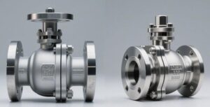
Torque Requirements
The medium thrust of a floating ball valve entirely presses on the downstream polymer seat; under ASME Class 600 or bore sizes larger than NPS 6, the surge in friction causes torque overload.
Trunnion ball valves absorb nearly 80% of the fluid thrust through upper and lower metal bearings.
Taking an NPS 8, Class 300 condition as an example, the breakaway torque of a trunnion ball valve is only 30% to 40% of a floating ball valve of the same specification.
Friction Distribution
According to ASME B16.34 calculations, in an NPS 6 pipeline under a Class 300 pressure rating, the upstream medium generates approximately 50,000 Newtons of thrust on the ball surface. This massive thrust completely translates into positive pressure between the ball and the downstream PTFE (polytetrafluoroethylene) seat. The frictional resistance is obtained by multiplying the positive pressure by the dynamic friction coefficient, and the friction coefficient of pure PTFE fluctuates in the range of 0.04 to 0.10.
PTFE seats under high load are highly susceptible to Cold Flow deformation, forcing the metal ball to deeply embed into the polymer material. The non-linear increase in contact area turns what was originally a narrow-band contact into full-wrap contact. The Breakaway Torque required to open the valve rises geometrically as a result. In a standard ambient water pressure test, the resistance of the first opening operation after being parked for 24 hours is 20% to 30% higher than during continuous action status.
To counter torque overload triggered by high thrust, engineers commonly select modified polymers as seat fillers.
- RPTFE (15% glass fiber reinforced PTFE): Compressive limit increases, friction coefficient rises to 0.12.
- Nylon: Strong load-bearing capacity, water absorption rate up to 2%, volume expansion increases friction resistance.
- Devlon V-API: Adapts to Class 600 medium-to-high pressure conditions, surface sliding friction resistance is at a medium level.
- PEEK (Polyetheretherketone): Withstands temperatures up to 250°C, hard texture, relative sliding of the sealing surface requires greater external force.
The structure of a trunnion ball valve introduces independent load-bearing bearings, entirely altering the force transmission path. The top of the ball connects to the stem, and the bottom inserts into a support shaft (Trunnion); 80% to 90% of the 50,000 Newtons of thrust generated by the medium is absorbed by the upper and lower metal bearings. The downstream soft seat no longer acts as the primary load-bearing component, enduring only the rear spring preload and roughly 10% of the residual fluid thrust.
Support bearings typically utilize DU bearings with a 316 stainless steel substrate lined with composite materials. A 0.01 to 0.03 mm thick mixture of PTFE and lead is sintered onto the surface of the DU bearing. The metal substrate provides a yield strength of up to 250 MPa, while the surface anti-friction material confines the sliding friction coefficient to an extremely low range of 0.02 to 0.05.
When withstanding a high differential pressure of Class 900 (about 150 bar), the friction resistance increment of a trunnion ball valve presents a gentle linear curve. The spring-loaded floating seat design maintains the contact squeezing force between the polymer face and the ball within a constant range. The springs supply initial preload, conventionally designed for a face pressure of 0.5 to 1.0 MPa, fully satisfying the low-pressure gas seal requirements at 0 bar differential pressure.
Pipeline systems frequently face massive temperature variations. As per API 6D specifications, valves need to maintain smooth operation across a wide temperature zone from -46°C to 200°C. When heated, the solid polymer seat of a floating ball valve has a linear expansion coefficient 10 times that of the metal valve body. The polymer, expanding under high temperatures with nowhere to release its excess volume, will tightly seize the ball, causing friction resistance to multiply exponentially.
The Belleville springs or cylindrical helical springs behind the trunnion ball valve’s seats reserve physical yielding space for thermal expansion. When the PTFE seat expands inward due to heat, the springs compress backwards by 0.2 to 0.5 mm, releasing the excess compressive stress on the sealing surface.
- Inconel X-750 Belleville Springs: Maintain stable spring force output at high temperatures, allowing the seat to retract slightly.
- O-ring Auxiliary Seal: Fluorocarbon rubber (FKM) material provides secondary elastic compensation, reducing hard contact friction.
- Graphite Fire-Safe Ring: Provides a low-friction metal-to-graphite backup seal guarantee after the polymer burns away.
The dry gas transported by natural gas pipelines offers no lubrication, which exacerbates dry friction between the metal ball and the non-metallic seat. Under a dry nitrogen test environment, the measured resistance value is typically 15% to 25% higher than in a hydraulic test. If the transported medium contains crude oil or grease, an oil film will fill the microscopic rough surfaces, decreasing the relative sliding resistance.
For Emergency Shutdown Valves (ESD) that remain in the open position long-term, static friction is an engineering margin that must be calculated. Even if the metal ball surface undergoes Electroless Nickel Plating (ENP) treatment, the surface roughness (Ra) is usually maintained at 0.1 to 0.2 microns. Over time, the microscopic metal peaks and valleys gradually embed into the soft polymer seat, creating mechanical interlocking.
The force required to overcome initial interlocking typically occurs the instant the valve opens (within a 0 to 15-degree rotation angle). To prevent pneumatic actuators from stalling, the output curve of a Scotch Yoke cylinder provides maximum starting thrust at the 0-degree position. When calculating actuator safety factors, engineers generally adopt 1.2 to 1.3 for clean lubricating fluids and must adjust up to 1.5 for dry gases.
The internal pressure relief mechanism of the valve body equally dictates the final trajectory of friction distribution. In the closed state of a DBB (Double Block and Bleed) trunnion ball valve, if abnormal pressure build-up occurs in the middle cavity, the seats will automatically spring outward to relieve pressure. When the cavity pressure exceeds the upstream pipeline pressure by approximately 1.5 to 3 bar, the pressure relief action instantaneously drops the localized friction resistance on the sealing surfaces.
Metal-to-metal hard-sealed ball valves introduce completely different friction coefficients. The ball surface is sprayed with Tungsten Carbide or Chrome Carbide, with a coating thickness of roughly 0.15 to 0.3 mm, and hardness can reach over 70 HRC. The sliding friction coefficient between two hard metals lies between 0.2 to 0.3, several times higher than that of soft-sealed polymers.
Hard-sealed trunnion ball valves must be paired with higher-strength leaf springs to sustain the specific sealing pressure. In order to slash the destructive forces brought on by high friction, the seat surfaces must be precision-lapped to achieve a conformity of over 99% with the ball’s contact area. Even so, the pneumatic cylinder volume of hard-sealed designs is universally 30% to 50% larger than that of soft-sealed trunnion ball valves of the same specification.
The connection flange at the top of the ball valve is manufactured according to ISO 5211 standards to receive the actuator’s output torque. Due to high frictional resistance, floating ball valves require a robust stem to prevent torsional fracture when overcoming static friction. The stem material is typically upgraded to 17-4PH precipitation-hardening stainless steel, possessing a tensile strength of over 1000 MPa, to tackle peak friction torques of up to several thousand Newton-meters.
Pneumatic actuator air supply pressure is generally set between 4.5 and 5.5 bar. Subtle changes in friction resistance mandate a proportional enlargement of the cylinder piston area. Because trunnion ball valves eliminate the high-pressure friction load of the downstream seat, the air source consumption of air compressors drops significantly, greatly slashing the energy load for offshore platforms and remote wellhead facilities.
Different Bore Sizes
The pipeline inner diameter size NPS 2 (approx. 50 mm) is a foundational dividing point for industrial valve selection. In a low-pressure ASME Class 150 pipeline, fluid thrust is small, and the opening torque of a floating ball valve remains in a low range of 25 to 35 Nm. With a manual lever operating length of 150 to 200 mm, an adult applying 150 Newtons of grip force with one hand can complete a 90-degree switch.
When the pipe diameter enlarges to NPS 4 (100 mm) and is under Class 300 (approx. 50 bar) conditions, the mechanical load on the polymer seat doubles. The theoretical breakaway torque of a floating ball valve climbs to 180 to 220 Nm, surpassing the physical limits of single-person operation. Codes mandatorily require the introduction of gear reducers or the installation of pneumatic actuators with a cylinder diameter of 80 to 100 mm.
A trunnion ball valve under the same NPS 4 conditions, relying on the diversion design of upper and lower bearings, can suppress the measured operating torque within the 90 to 110 Nm range. The actuator size can be scaled down by one model; for instance, selecting a light-duty cylinder with an output torque of 120 Nm will, on average, reduce the overall assembly weight by 12% to 15%. At a standard 5.5 bar air supply pressure, the smaller cylinder consumes about 0.8 liters less compressed air volume per stroke.
Transitioning to NPS 6 (150 mm) medium-sized pipelines, the torque disparity between the two mechanical designs widens exponentially. Enduring a high differential pressure of Class 600 (approx. 100 bar), the polymer seat of an NPS 6 floating ball valve bears a fluid compressive force of over 120,000 Newtons. The opening torque breaks through 1200 Nm, making standard rack and pinion actuators too bulky for stable installation.
- NPS 6 (Class 150): Floating torque approx. 280 Nm, equipped with ISO F10 flange, 22 mm OD stem.
- NPS 6 (Class 300): Floating torque approx. 650 Nm, equipped with ISO F12 flange, 28 mm OD stem.
- NPS 6 (Class 600): Trunnion torque approx. 450 Nm, equipped with ISO F12 flange, 28 mm OD stem.
- NPS 6 (Class 900): Trunnion structure only, torque approx. 880 Nm, equipped with ISO F14 flange, 36 mm OD stem.
NPS 8 (200 mm) is strictly defined in API 6D specifications as the engineering upper limit for floating ball valves. Even in an ultra-low pressure Class 150 environment, the opening resistance of an NPS 8 floating ball valve can reach 800 Nm. Once system pressure leaps to Class 300, cold flow deformation of the sealing surface caused by thrust is practically inevitable, and a frictional resistance as high as 2500 Nm easily snaps standard material stems.
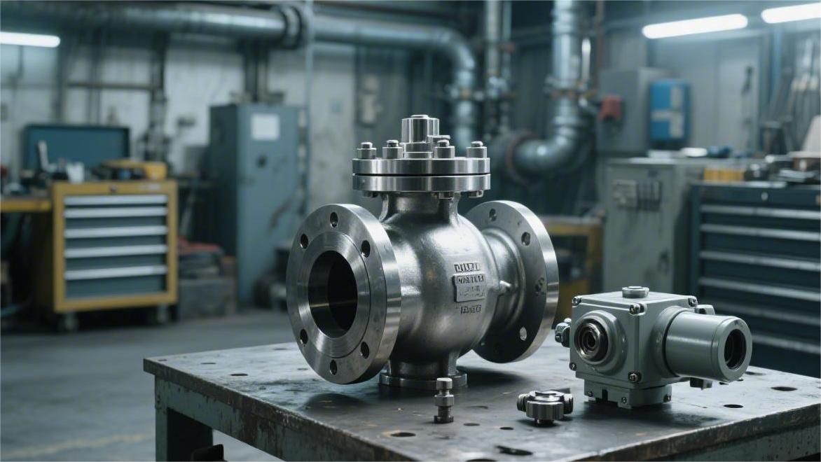
As pipelines extend from NPS 8 to NPS 12 (300 mm), the trunnion ball valve becomes the only compliant structural option. For NPS 12, Class 600 heavy-duty environments, the upper and lower support bearings stably control the sliding friction torque between 1800 and 2200 Nm. The top connection pad is upgraded to F16 or F25 specifications, equipped with 4 or 8 rows of M20 high-strength mounting bolts.
Driving large-bore trunnion ball valves requires pairing with heavy-duty Scotch Yoke pneumatic actuators. The Scotch Yoke mechanism’s U-shaped power output curve provides peak thrust at the 0-degree and 90-degree valve positions. A Scotch Yoke cylinder adapted to an NPS 12 valve has a single-sided piston diameter reaching 250 mm, a length exceeding 1.2 meters, and a dead weight hovering around 180 to 250 kg.
| Size and Pressure Class | Trunnion Ball Valve Torque (Nm) | Stem Top Flange | Pneumatic Actuator Piston Estimate |
|---|---|---|---|
| NPS 16 (Class 300) | 3500 – 4200 | ISO F25 | Single side approx 300 mm |
| NPS 20 (Class 600) | 8500 – 10000 | ISO F30 | Single side approx 400 mm |
| NPS 24 (Class 900) | 16000 – 19500 | ISO F35 | Single side approx 500 mm |
| NPS 36 (Class 600) | 32000 – 38000 | ISO F40 | Single side approx 700 mm |
When the bore of natural gas transmission pipelines reaches NPS 24 (600 mm), the medium thrust breaks the million-Newton mark. In Class 900 ultra-high pressure oil and gas trunklines, the opening torque skyrockets to 15,000 to 20,000 Nm. The stem diameter must be thickened to over 80 mm and molded from Duplex 2205 duplex stainless steel with a tensile strength of 800 MPa.
Under extreme torque conditions, the actuator output shaft and valve stem utilize a keyway connection. For heavy equipment above NPS 24, the stem needs to be machined with two or three rectangular keyways 20 mm in width. The multi-keyway distribution uniformly disperses the peak 20,000 Nm torsional stress across the metal surface, preventing localized shear forces from exceeding the yield limit.
Operating time settings are dually constrained by cylinder volume and bore size enlargement. A light NPS 2 ball valve completes a full open/close stroke in less than 1 second under a 5.5 bar air source. The internal volume of an NPS 24 heavy-duty Scotch Yoke cylinder exceeds 80 liters, and equipped with a large-flow solenoid valve with a Cv value of 5.0, completing a single 90-degree stroke takes 15 to 25 seconds.
The wider the pipe inner diameter, the greater the internal component impact force from the Water Hammer effect caused by the flowing medium. In liquid pipelines NPS 16 and above, closing speeds faster than 10 seconds will generate pressure spikes of tens of bars upstream. Engineers install one-way throttle valves in the actuator’s air circuit to stretch the exhaust time to over 30 seconds.
- Exhaust Throttling: Liquid valves NPS 16 and above must be fitted with flow control valves to retard closing speed.
- Air Chamber Volume: NPS 24 cylinder inflation requires a minimum 200-liter backup Air Receiver.
- Torsional Limit: The calculated shear safety factor for stem material must be adjusted up to 2.0 for large NPS 36 bores.
- Hydraulic Overload: Class 900 ultra-large bore valves opt for electro-hydraulic actuators to output Megapascal-level thrust.
When expanding to NPS 36 (900 mm), conventional factory pneumatic networks struggle to provide stable, massive thrust. Operating torques frequently breach the physical extreme of 40,000 Nm, making reliance on high-pressure hydraulic power units essential for power. The pipeline system is injected with ISO VG 32 viscosity grade anti-wear hydraulic oil, driving a double-acting hydraulic cylinder at a system pressure of 150 bar.
The enormous dead weight of the valve alters the design logic of the support structure. An NPS 36, Class 600 trunnion ball valve often has a total weight exceeding 12 tons, with an additional actuator dead weight of about 3 tons. Carbon steel Support Legs with pre-drilled holes are additionally welded to the bottom, using 4 M36 anchor bolts to secure it firmly to a concrete foundation.
Actuator Assembly Pairing
The API 6D specification dictates that the connection point between the stem and the drive equipment must withstand a shear force of 1.5 times the rated torque. An NPS 8 floating ball valve under Class 300 pressure generates about 1800 Nm of resistance, requiring pairing with an F16 heavy-duty flange from the ISO 5211 standard.
The F16 flange specification has an outer diameter of 210 mm and is fitted with 4 M20 bolt holes to endure immense torsional stress. The frictional resistance of an equivalent NPS 8 trunnion ball valve drops to 550 Nm, and the flange specification is correspondingly reduced to F12. The F12 flange outer diameter is only 150 mm and is secured using M16 bolts.
For every ISO standard size increase in flange diameter, the carbon steel consumption of the matching mounting Bracket rises by an average of 4.5 kg. The thickness of the transition piece increases from 15 mm to 25 mm, extending machining time by about 40 minutes.
Mounting large pneumatic equipment on a floating structure creates eccentric loads. Taking a Scotch Yoke actuator with a 2000 Nm output torque as an example, its cast iron housing and internal double pistons total over 180 kg in weight.
Hanging 180 kg of heavy accessories mid-air above the pipeline offsets the center of gravity by about 300 mm from the valve’s central axis. The gravity moment applies additional bending stress to the NPS 8 pipe flanges. Prolonged gravitational pulling leads to metal fatigue, making it mandatory under ASME B31.3 codes to install independent load-bearing supports at this location.
- Gravity Sag: Actuators over 150 kg require a channel steel base configuration, with the support point roughly 500 mm from the pipeline centerline.
- Lateral Load: Eccentric gravity generates one-sided compression at the stem packing box, causing unilateral wear exceeding 0.2 mm on the PTFE V-rings.
- Vibration Displacement: Low-frequency 10 to 50 Hz vibrations inside compressor pump rooms amplify the displacement amplitude of top-heavy objects to 2 mm.
- Spatial Interference: The total length of a Scotch Yoke cylinder exceeds 1.2 meters, requiring the center-to-center distance of adjacent parallel pipelines to be widened to over 1.5 meters.
The low resistance trait of trunnion ball valves permits factories to widely procure lightweight Rack & Pinion cylinders. A rack and pinion cylinder outputting 550 Nm of torque features an extruded aluminum alloy casing, keeping the total machine weight at around 28 kg.
The 28 kg lightweight assembly entirely bypasses the need for extra pipeline support systems. Internally, it utilizes a dual-piston design symmetrically compressing the pinion shaft towards the center, canceling out lateral thrusts. The stem is immune from bending tension, and the graphite seal rings at the packing box are uniformly stressed, prolonging lifespan to 50,000 on/off cycles.
The air chamber volume inside drive equipment alters the load on the instrument air network. A rack and pinion cylinder completes a single 90-degree stroke consuming merely about 3.5 liters of 5.5 bar compressed air. The single inflation time of chemical plant air compressors is kept under 0.5 seconds, and the solenoid valve exhaust can also purge the inner cavity within 1 second.
To output 1800 Nm of torque, a massive Scotch Yoke cylinder has a single-sided air chamber volume up to 15 liters. The compressed gas volume consumed in a single stroke is over 4 times that of a light cylinder. For remote wellhead unmanned platforms reliant on solar power and small accumulators, frequent exhausting triggers an instantaneous 0.5 bar drop in network pressure.
When the instrument air network pressure falls below 4.0 bar, the Spring Return function of pneumatic components cannot overcome the static friction of the valve, causing the piston to stall midway.
The unit price of imported 2000 Nm class Scotch Yoke pneumatic actuators on the market ranges between $4,500 and $5,500. Companion large-flow air filter regulators and limit switch boxes push the procurement cost of a single set of automation components close to $6,000.
The unit price of a 550 Nm class lightweight aluminum alloy cylinder paired with a trunnion ball valve usually does not exceed $900. Including accessories with NAMUR standard interfaces, the total budget is kept within $1,200. In a process unit with 40 shutdown valve points, the actuator item alone can slice nearly $190,000 off initial investments.
- Procurement Price Gap: Light cylinder unit price $900 vs heavy Scotch Yoke cylinder unit price $5000, a stark contrast.
- Accessory Downgrade: Reduced air consumption allows downgrading the 1/2-inch stainless steel air supply line to a 1/4-inch specification.
- Solenoid Valve Matching: Large explosion-proof solenoid valves with a Cv of 3.0 are swapped for standard compact products with a Cv of 0.9.
The accumulation of mechanical tolerances in the stem connection area dictates final operational precision. The high torque of a floating structure demands broad rectangular keyways machined at the top of the stem. A 14 mm wide flat key and keyway have an assembly clearance of 0.05 to 0.10 mm.
After enduring multiple high-frequency reversing impacts, the 0.10 mm clearance gradually expands to over 0.25 mm. As the piston begins moving, the main shaft experiences an idle Deadband of about 1 to 2 degrees. The deadband delays the time it takes the ball bore to shut off fluid, causing an extra leakage of approximately 5 liters of medium per second.
Low-resistance trunnion ball valves predominantly use Double-D or Spline connections. A 28 mm OD Double-D stem features parallel flats machined on both sides, achieving an interference fit with the hex hole at the base of the cylinder. Sliding deadband is compressed to under 0.1 degrees.
Spline connections maintain rigidity when outputting high-frequency modulating commands. Servo motor-driven electric actuators adjust opening degrees at a stepping speed of 5 mm per second. Zero-clearance star gears transmit motor torque losslessly to the metal ball, achieving a flow control precision of five thousandths of the design rating.
Electric actuator power consumption selection is built upon underlying resistance tests. A 550 Nm frictional force only requires a 0.35 kW three-phase AC motor. Operating current stays below 1.5 Amps, and standard insulated cables with a 1.5 mm² cross-section easily meet long-distance power supply needs.
Facing a high load of 1800 Nm, motor power must jump a tier to 1.5 kW or higher. The peak current at start-up breaches 15 Amps. Electrical engineers must lay armored cables with a 4 mm² cross-section and upgrade corresponding contactor and thermal relay capacities in the MCC control cabinet.
As the power cable OD thickens from 10 mm to 16 mm, cable routing weight per 100 meters of cable tray increases by about 12 kg, and the bending radius widens to 10 times the wire diameter.
Outdoor extreme cold environment testing exposes physical limits in material stress distribution. In a -40°C polar mining area, the nitrile rubber (NBR) O-rings inside cylinders lose elasticity. Cold fluids push the operating resistance of an NPS 8 floating ball valve to a staggering 2500 Nm.
Large Scotch Yoke cylinders suffer a thrust decay of about 20% due to reduced airtightness. Overlapping mechanical resistance and power deficit force field operators to use 1.5-meter long manual hydraulic pumps for physical intervention. Pumping the lever only rotates the valve by 0.5 degrees, making a full closure take over 5 minutes.
- Low-Temperature Resistance: At -40°C, PTFE face pressure increases, driving starting friction torque 40% higher than at room temperature.
- Hydraulic Overload: Manual pumps output a maximum of 200 bar hydraulic pressure, forcibly advancing the piston to overcome mechanical sticking.
- Response Delay: Emergency shutdown action surges from a standard 5 seconds to several minutes, voiding the original setup.
Lightweight equipment paired with trunnion ball valves maintains engineering redundancy in severe cold. The inherently low 550 Nm baseline, even with a 40% resistance hike due to cold, safely remains in a reasonable 770 Nm range. By upgrading internal seals to low-temperature resistant silicone rubber, the cylinder can still complete its stroke in 3 seconds at -40°C.
Sealing Stability
In high-pressure conditions above Class 300, the full differential pressure acts upon a single polymer seat, making PTFE materials prone to plastic deformation that causes leakage.
Trunnion ball valves employ spring-loaded floating seats, relying on mechanical preload to preserve an initial seal in a 0 psi zero-pressure state.
Fluid thrust is absorbed by the upper and lower trunnions, allowing the seat to endure pressure differentials up to Class 2500 (approx. 420 bar) without extrusion rupture, with long-term leak rates satisfying ANSI/FCI 70-2 Class VI standards.
Performance Across Different Pressures
When internal pipeline pressure is beneath 30 psi, the fluid thrust pushing against the ball is less than 100 pounds. The floating ball only undergoes a miniscule physical shift of 0.1 to 0.5 millimeters.
Contact stress on the surface of the downstream PTFE seat fails to reach the extremely low minimum requirement of 2 N/mm². The medium permeates along micro-level surface roughness gaps, pushing the internal leak rate past the API 598 standard allowance of 12 drops per minute.
Mechanical preload designs reinvent the stress model under no-pressure states.
The Inconel X-750 wave spring groups behind the seats deliver a constant 80 to 120 pounds of initial thrust.
Spring deformation is controlled within the 1.5 to 2.5 mm range. Contact specific pressure on the sealing face is forcefully elevated above 3.5 N/mm², establishing a zero-leakage initial physical barrier under 0 psi conditions.
As system pressure begins building and hits the ASME Class 150 rated cap of 285 psi, fluid thrust multiplies geometrically. For an 8-inch (DN200) size, the effective cross-sectional area of fluid acting on the ball is roughly 324 square centimeters. The lateral thrust created by the differential pressure reaches around 6400 pounds (28.5 kN). The thrust tightly presses the ball onto the downstream single-sided RPTFE (reinforced PTFE) seat.
The material surface withstands approximately 8 MPa of compressive stress, a value well beneath RPTFE’s yield strength limit of roughly 14 MPa.
- The contact face undergoes an elastic deformation of about 0.2 mm, filling micro-scratches on the metal ball’s surface.
- A Bubble-tight seal is successfully established.
- The pass rate for ANSI/FCI 70-2 Class VI pneumatic testing exceeds 99%.
System pressure continues climbing to the Class 300 critical point (up to 740 psi). The floating ball is subjected to thrust breaking 16,000 pounds (71 kN), and the compressive stress bearing down on the single-sided non-metallic seat nears 12 MPa. The polymer material enters a non-linear elastic zone, where prolonged pressure will spawn irreversible creep.
Once operations transition to the Class 600 tier, normal ambient working pressures reach 1480 psi (102 bar). A floating ball in a 10-inch pipeline is pitted against an immense physical thrust towering at 75,000 pounds (333 kN).
Over 30 MPa of crushing stress instantaneously pierces the yield limits of conventional seat materials. PTFE experiences a Cold Flow phenomenon, oozing outward along the clearance between the ball and the metal valve body, thinning out the cross-sectional thickness by over 30%.
A stress distribution mechanism takes over the destructive loads brought by high-pressure fluids. The top and bottom forged steel trunnions, 2.5 inches (63.5 mm) in diameter, absorb over 95% of the lateral thrust. Trunnion shear stress is maintained below 40% of the material’s allowable strength, yielding only microscopic elastic bending (less than 0.05 mm). The ball remains fixed at the geometric center by the trunnions, capping eccentric displacement under 0.02 mm.
The spring-loaded floating seats only need to handle the thrust generated by the fluid’s Piston Effect, sparing them from tens of tons of primary thrust crushing.
High-pressure fluid acts on the annular step area at the back of the seat. The seat back ring, with a 200 mm OD and 180 mm ID, creates a 1.2:1 proportional discrepancy with the front sealing face’s cross-sectional area.
The auxiliary thrust produced by the fluid pressure multiplied by this area differential smoothly propels the Devlon V-API seat toward the stationary ball. Sealing stress is precisely confined to a safe working range of 20 MPa to 25 MPa.
When the pipeline is transporting liquid hydrocarbons and the ambient temperature climbs from 15°C to 50°C, the volume of locked-in liquid within the valve cavity expands. Dictated by the laws of thermal expansion, the hydraulic pressure inside the sealed chamber skyrockets 70 psi for every 1°C surge.
Floating ball valves lack an architecture to actively discharge cavity overpressure. An abnormal internal surge of 1000 psi will simultaneously push both upstream and downstream seats outward. The fluid jets out instantly, and in severe cases, causes the valve body connecting bolts to suffer tensile fracture exceeding material yield strengths.
The Single Piston Effect (SPE) seat remedies the physical expansion issues of internal overpressure. When cavity pressure exceeds upstream pipeline pressure by 133% (e.g., pipeline is 1000 psi, cavity hits 1330 psi), the pressure relief mechanism initiates.
Cavity fluid overpowers the 120-pound preload of the rear springs, pushing the upstream seat in reverse, away from the ball’s surface.
- The seat yields a reverse displacement of roughly 0.5 mm.
- Overpressurized medium bleeds back into the upstream pipeline at 2 liters per second.
- After cavity pressure falls back to 1000 psi, the springs snap the seat closed again in 0.1 seconds.
Tougher pressure-bearing demands extend up to Class 2500 (operating pressures hit 6170 psi, approx. 425 bar). In North Sea oilfield gas injection wellhead tasks, operational pressures frequently sit above 5000 psi.
These systems are outfitted with PEEK (Polyetheretherketone) high-polymer seats. PEEK boasts a compressive strength soaring to 110 MPa, capable of enduring extreme face specific pressures without shattering.
During split-second opening or closing operations spanning a 300 bar differential, fluid velocity shatters the speed of sound (exceeding 340 meters/second). The high-speed medium inflicts potent cutting and scouring forces against the seats.
Bidirectional Isolation and Leak Testing
In a closed state, a floating ball valve faces a 600 psi (approx. 41.3 bar) upstream fluid thrust. The ball undergoes a 0.3 mm physical displacement to one side, forging a 0.1 mm gap between the upstream seat and the ball surface. Pipeline medium smoothly breaches the valve’s middle cavity, entirely failing to provide physical isolation on both ends.
If operators unscrew the 1/2-inch NPT threaded bleed plug at the bottom of the valve body at this moment, 600 psi high-pressure fluid will jet out at over 5 liters per second. Maintenance teams have absolutely no means of determining if the downstream pipeline’s PTFE seat is suffering an internal seepage rate exceeding 20 milliliters per minute.
The upper and lower trunnions of a trunnion ball valve absorb 99% of the pipeline fluid’s axial thrust. The backs of both floating seats on either side are each furnished with 12 to 24 Inconel 718 cylindrical helical springs. Whether pipeline pressure is 10 psi or 1500 psi, the spring groups continuously supply a steady 80-pound thrust.
Both independent seats simultaneously sever the fluid paths leading into the valve’s middle cavity from upstream and downstream. API 6D specifications detail the leak-testing protocol for DBB (Double Block and Bleed) physical structures. Technicians unscrew the middle cavity bleed valve, releasing the 1.5 liters of residual medium originally inside.
- Close the main valve and apply 900 psi rated hydrostatic pressure.
- Open the cavity bleed valve to atmospheric pressure (0 psi).
- Continuously observe the physical state of the bleed port for 5 to 10 minutes.
- Zero dripping (0 drops/min) signifies both seats are perfectly sealed against the ball.
- Employ specialized leak detection fluid to screen for micro-level bubble seepage.
With the bleed valve held open, middle cavity pressure plunges to 0 psig. The upstream pipeline maintains a towering 1440 psi, while the downstream pipeline sits empty at 0 psi. Subjected to the dual forces of spring preload and the fluid piston effect, the upstream side seat fabricates 15 MPa of contact specific pressure.
International standard ISO 5208 mandates that Rate A seal tests must accomplish zero leakage. Upon undergoing hydrostatic tests, a 12-inch (DN300) trunnion ball valve permits not even 0.1 milliliters of liquid to bleed into the cavity. Any minute internal leak will trickle down the bleed pipe, captured visually or by an ultrasonic flow meter (detection limit 0.05 m/s).
Rigorous petrochemical refining units call for the stricter DIB-1 (Double Isolation and Bleed, both seats bidirectional) standard. Both seats are upgraded to Double Piston Effect (DPE) configurations. If one side’s seat loses spring preload or suffers mechanical damage, the seat on the opposite side will still furnish a high-pressure physical barricade.
- Pipeline pressure pushes the seat toward the stationary ball surface.
- During middle cavity overpressure, fluid acts on the outer step of the seat.
- The inner to outer cross-sectional area ratio hits 1:1.3.
- 1000 psi pressure in the middle cavity reverse-pushes the seat against the ball.
- This forms a dual pressure-bearing defense for a single seat in both directions.
A DIB-2 configuration fuses Single Piston Effect (SPE) and Double Piston Effect (DPE) seats. The upstream is rigged with an SPE seat to provide an automatic relief path, and the downstream is armed with a DPE seat as an ultimate defense line. When middle cavity pressure surpasses upstream pipeline by 200 psi, the SPE seat retracts 0.5 mm to dump excess fluid.
Pipeline repair crews enter a confined natural gas pipe segment for welding operations, standing merely 1.5 meters from the valve flange. The upstream natural gas pipeline pressure runs up to 800 psi and packs 3% highly toxic H2S gas. The DBB feature serves as a physical containment wall in this instance.
The cavity bleed port is hooked to a 3/8-inch OD stainless steel drain hose, redirecting seeped gas to a flare boom for incineration. Even if the upstream seat springs a micro-leak of 50 cubic centimeters per minute, the gas is entirely evacuated from the middle cavity. The bleed route ensures that middle cavity pressure forever remains at absolute atmospheric pressure.
The downstream DPE seat is immune to any fluid thrust crushing. The natural gas concentration on the worker’s side of the work zone remains securely beneath the 10 ppm safe exposure limit, stringently aligning with OSHA confined space protocols. Swapping the scene to a floating ball valve, the moment a worker removes the downstream flange bolts, the ball sheds the physical support of the downstream seat.
- Lacks the metal anchoring of upper and lower trunnions.
- Blind flanges become the sole isolation tactic during pipe swaps.
- Requires entirely venting the entire 20-kilometer stretch of high-pressure gas before severing the line.
- Line depressurization and nitrogen purging burns through 48 to 72 hours of downtime.
On an FPSO (Floating Production Storage and Offloading unit) pumping out 50,000 barrels of crude a day, every hour of mechanical downtime bleeds $65,000 in lost revenue. Trunnion ball valves empower engineers to physically isolate a single 10-foot (approx. 3-meter) fluid pipe segment while the system operates live at 1500 psi. Field personnel round off the entire leak test protocol by applying 45 N·m of fastening torque to the bleed valve via a torque wrench.

")