
The overall performance of trunnion ball valves is generally superior. Floating ball valves rely on fluid thrust to press the ball for sealing, making them suitable for low-pressure applications of 6 inches and below Class 300. Under high pressures, their operating torque becomes exceptionally large and they are prone to wear.
The ball of a trunnion valve is supported by upper and lower shafts, shifting to a design where spring-energized seats move to create the seal. This significantly reduces its operating torque, making it perfectly capable of handling extreme pressures from Class 600 to 2500, as well as large-diameter API 6D pipelines up to 60 inches.
Torque
Taking an ASME Class 300 (maximum allowable working pressure of approx. 740 psi), 6-inch diameter valve as an example, a floating ball valve relies entirely on the fluid pressure differential to push the ball into the polytetrafluoroethylene (PTFE) non-metallic seat. The frictional resistance generated by the high pressure differential usually causes the opening and closing torque to climb above 1500 N·m.
A trunnion ball valve absorbs the vast majority of the line thrust through its upper and lower trunnion shafts and bearings, using springs to actively push the seats against the ball. Under the same physical parameters, the torque can be maintained between 400 and 600 N·m.
This massive disparity in base torque means that floating ball valves in large-diameter or high-pressure scenarios must be paired with heavy-duty pneumatic actuators with large cylinder bores. The hardware procurement cost for these actuators often exceeds 40% to 60% of the budget for the bare valve itself.
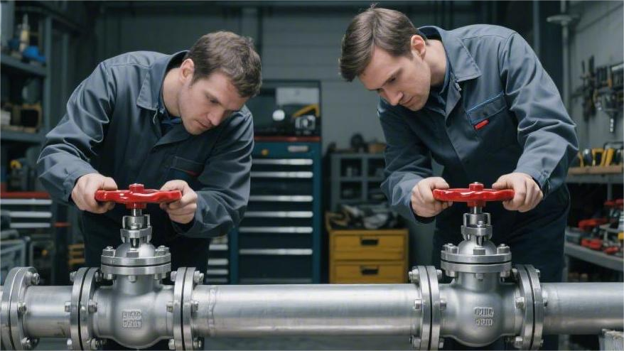
Floating vs. Trunnion
Under the API 6D specification, the ball of a floating ball valve is supported by PTFE or PEEK seats on both sides, remaining in a suspended state. The fluid pressure differential in the pipeline pushes the 316 stainless steel ball downstream, compressing the sealing ring on a single side. When the pipe diameter remains in the 2-inch to 4-inch range, the high-molecular polymer of the seat has sufficient yield strength to withstand this thrust.
When the pipe size expands to 8 inches or 12 inches, the geometric growth of the cross-sectional area causes the axial fluid thrust to surge to tens of thousands of pounds. The trunnion structure introduces a blowout-proof stem at the top of the ball and adds a load-bearing trunnion plate at the bottom, anchoring the ball at the geometric center of the valve body.
The trunnion surface is covered with 316L bearings featuring a PTFE composite backing, which absorbs up to 90% of the pipeline media thrust. The downstream seat no longer bears the compression load from the ball, drastically reducing the physical wear rate.
- Support Components: Floating valves solely rely on non-metallic seats on both sides to support the ball.
- Trunnion Assembly: Trunnion valves feature an independent support shaft and self-lubricating bearing at the bottom.
- Spring Configuration: Trunnion valves are equipped with Inconel X-750 wave springs behind the seats.
- Pressure Relief Mechanism: Trunnion valves come standard with a DBB (Double Block and Bleed) bleed valve port.
The transfer of physical loads brings a change in the sealing mechanism. The sealing of a floating structure is a unidirectional passive compression. When the media pressure is below 50 psi, it relies merely on the slight mechanical interference from assembly to maintain initial contact. In low-pressure gas lines, insufficient interference easily leads to ISO 5208 Rate B trace leakage.
Trunnion ball valves adopt a bi-directional active push mechanism, with O-rings or pure graphite rings embedded in the inner ring of the upstream and downstream seat assemblies. Internally, 12 to 24 high-strength Belleville springs are arranged to continuously apply a pre-load of over 150 lbs to the seat.
Even if the pipeline is at a 0 psi zero-pressure state, the spring groups still push the left and right floating seats tightly against the stationary ball. After ASME Class 900 (approx. 2220 psi operating limit) high-pressure fluid enters the valve cavity, the Piston Effect converts the media pressure into additional auxiliary thrust.
- Low-Pressure State: Floating valves rely on seat interference fit; trunnion valves rely on spring pre-loading.
- High-Pressure State: Floating valve ball displacement compresses one side; trunnion valve media pushes seats for bi-directional contact.
- Pressure Relief Function: Trunnion valves have the capability to automatically release abnormal pressure build-up in the central cavity.
In NACE MR0175 wet H2S environments, liquid hydrocarbons trapped inside the valve cavity expand when heated, creating high pressure that exceeds 1.5 times the system rating. The Single Piston Effect (SPE) seats of trunnion ball valves have a pressure differential relief threshold set between 25 to 100 psi.
When the cavity pressure is 50 psi higher than the upstream pipeline, the expansion force overcomes the thrust of the Inconel springs, pushing the upstream seat away from the spherical surface by about 0.5 mm. The accumulated high-pressure fluid instantly flows back into the upstream pipeline, preventing plastic deformation of the ASTM A105 forged steel valve body.
Valve manufacturers’ product catalogs usually set the 6-inch diameter as a physical watershed. Class 150 6-inch pipelines can be fitted with cast WCB floating valves, keeping the total weight under 85 kg and project costs in a lower bracket.
When jumping to the Class 600 pressure rating, API 6D strictly mandates that sizes above 6 inches must switch to a trunnion-mounted structure. The ASME B16.34 wall thickness calculation formula requires a Class 1500 8-inch trunnion ball valve to have a flange thickness of 82.6 mm.
The API 607 fire test standard imposes rigid performance indicators for the high-temperature response of both structures. When the test furnace temperature rises to the 760°C to 980°C range, nylon or PEEK primary sealing rings will completely melt within 15 minutes.
Pushed by 30 psi of residual pipeline pressure, the ball of a floating valve slides backward by about 2 mm, pressing against the metallic valve body lip machined with a 5-degree angle. The trunnion valve, however, relies on backing springs to push the metallic seat skeleton—now stripped of its soft seal—toward the ball, forming a metal-to-metal secondary fire-safe seal.
- Soft Seal Meltdown: The first line of polymer sealing vaporizes and disappears in high-temperature environments.
- Displacement Compensation: The floating valve ball shifts backward; the trunnion valve relies on springs to push a step further.
- Metallic Contact: A sharp metal lip forms a 360-degree line contact with the spherical surface to block fluid.
During offline maintenance, trunnion ball valves equipped with a Drain Valve allow operators to verify seal integrity without shutting off the pipeline flow. While the pipeline maintains an operating pressure of 1000 psi, opening the drain port reveals no fluid spilling from the central cavity, proving the bi-directional seal meets zero-leakage standards.
A 16-inch long-distance crude oil pipeline typically utilizes a three-piece forged steel trunnion ball valve, with the valve body fastened by 24 ASTM A193 B7 high-strength studs. Floating ball valves are mostly two-piece structures; during overhauls, the upstream and downstream flange connections must be cut off, and the entire valve body, weighing over 50 kg, must be removed from the line to a workbench.
The API 6D standard sets strict duration requirements for bi-directional seal testing. For 10-inch specification products, a hydrostatic test at 1.1 times the design pressure must be maintained for at least 3 minutes, with operators continuously monitoring the condition of the drain valve port.
The Double Piston Effect (DPE) seat configuration introduces the higher safety redundancy DIB-1 testing standard. In 20-inch natural gas mainline block valves, both front and rear seats are equipped with high-tension spring sets. When a single-sided media pressure reaches 1480 psi, both upstream and downstream seats simultaneously apply a bi-directional compressive force against the ball.
Thermodynamic environmental changes require engineering designs to reserve physical expansion gaps. For an A105 forged steel valve body operating continuously at 150°C, its thermal expansion coefficient is approximately 11.7 µm/m·°C. Trunnion designs leave 2 to 3 mm of mechanical clearance at the bottom of the valve body to relieve stress.
Testing Same Specifications
In an independent third-party laboratory in Houston, a comparative sampling was conducted on two valves with identically rated specifications according to the API 6D 24th edition specification. The test subjects were both 6-inch, ASME Class 600, Full Port flanged ball valves. The testing media utilized purified water at 20°C and industrial nitrogen of 99.9% purity, with the pipeline providing a continuous single-sided hydrostatic differential pressure of 1480 psi.
The first tested valve featured a traditional two-piece cast WCB floating ball structure, equipped with RPTFE (containing 15% glass fiber) seats. The second was a three-piece forged A105 trunnion ball structure, utilizing RPTFE inserts with the same friction characteristics, provided with 180 lbs of initial pre-load by Inconel 718 springs. Instruments connected a digital dynamic torque sensor with a range of 5000 N·m to the top of the stems to record torque curves throughout the opening and closing cycles.
| Test Phase / Torque Parameter | 6″ Class 600 Floating Ball Valve | 6″ Class 600 Trunnion Ball Valve |
|---|---|---|
| Break to Open (BTO) | 2845 N·m | 890 N·m |
| Run to Open (RTO) | 1650 N·m | 520 N·m |
| End to Open (ETO) | 1820 N·m | 610 N·m |
| Break to Close (BTC) | 2790 N·m | 875 N·m |
| Run to Close (RTC) | 1580 N·m | 510 N·m |
The BTO peak data captured by the sensor demonstrated a 26,800-pound axial thrust generated when a 1480 psi hydrostatic differential acted on the surface of a 152 mm diameter ball. The 316 stainless steel trunnion bearing with a 2 mm thick PTFE coating in the trunnion structure carried a 24,000-pound load. The floating structure transferred all thrust to the downstream 12 mm wide RPTFE sealing ring, pushing the contact surface specific pressure to 3500 psi.
Pneumatic Actuator Sizing Baseline Data Sheet:
- Floating Valve Actuator: Single-acting scotch yoke; output torque required > 3698 N·m (including a 30% safety factor).
- Trunnion Valve Actuator: Double-acting rack and pinion; output torque set to 1157 N·m.
- Cylinder Supply Pressure: Same air supply network providing 80 psi compressed air.
- Cylinder Air Consumption: Floating valve actuator consumes 14.5 liters per stroke; trunnion valve consumes 4.2 liters.
Actuator flange interface dimensions showed hardware matching differences under the ISO 5211 standard. The floating ball valve’s BTO of up to 2845 N·m required a stem diameter of 45 mm, and the top mounting pad needed an F14 specification (140 mm bolt circle diameter). The trunnion ball valve’s 890 N·m torque only required a 32 mm diameter 17-4PH precipitation-hardened stainless steel stem, shrinking the flange interface to an F12 specification.
The subsequent Hydrostatic Shell Test removed the actuators and injected test water containing fluorescent tracers into the central cavity while in the open position. A pressure pump elevated the internal pressure to 1.5 times the 100°F rated working pressure, or 2225 psi, within 45 seconds. The hold time was extended to 15 minutes as per API 6D; the ASTM A193 B7 fastening studs on both valves did not undergo elastic deformation exceeding 0.05 mm, and external surface penetration showed zero leakage.
The High-Pressure Hydrostatic Seat Test alternately applied 1630 psi of unidirectional water pressure to both sides of the ball. The trunnion ball valve’s central cavity drain valve was fully open, collecting any leaked fluid via a graduated cylinder for 5 minutes. Test records indicated the trunnion valve’s drain port remained bone dry, fully complying with the ISO 5208 Rate A zero leakage class.
| High-Pressure Hydrostatic Seat Test (1630 psi) | Leakage Test Standard | Actual Measured Data (5 mins) |
|---|---|---|
| Floating Ball Valve (Single-sided Pressure) | ISO 5208 Rate B | 0.8 ml/min |
| Floating Ball Valve (Reverse Pressure) | ISO 5208 Rate B | 1.1 ml/min |
| Trunnion Ball Valve (Upstream Pressure) | ISO 5208 Rate A | 0.0 ml/min |
| Trunnion Ball Valve (Downstream Pressure) | ISO 5208 Rate A | 0.0 ml/min |
The Low-Pressure Gas Seat Test switched to 80 psi of dry nitrogen to test the initial seal interference. The floating ball valve relied on a 0.5 mm physical squeeze from assembly to maintain its seal at low pressure; the bubbling frequency in water was twelve 3 mm diameter bubbles per minute. The 24 Inconel springs behind the trunnion ball valve continuously provided 180 lbs of thrust, and the water immersion observation method captured absolutely no nitrogen escaping over 5 minutes.
The High-Density Cycle Life Test connected both valves to an automated hydraulic console. Maintaining a 1480 psi media pressure, opening and closing actions were performed at a frequency of 2 times per minute. When the counter hit 1,500 cycles, the digital torque meter showed the floating ball valve’s RUN torque slowly climbing from an initial 1650 N·m to 1980 N·m.
- Component wear analysis indicators after 1500 cycles:
- Downstream Seat Thickness: Floating valve RPTFE seat compressed from 12.0 mm to 10.8 mm.
- Trunnion Bearing Condition: Trunnion valve bottom PTFE bearing pad wear was less than 0.1 mm.
- Torque Fluctuation Rate: Floating valve opening/closing resistance increased by 20%; trunnion valve remained within a 3% error margin.
- Stem Packing Leakage: Both sets of pure Graphite packing maintained 0 ppm of volatile organic compound fugitive emissions.
The teardown and measurement phase utilized a Coordinate Measuring Machine (CMM) to scan the surface roughness (Ra) of the 316 stainless steel balls. The original unblemished spherical surface Ra value was denoted at 0.15 µm. After enduring high-pressure differential friction, the Ra value of the floating valve’s contact area degraded to 0.45 µm, showing fine axial scratches 0.2 mm wide. The non-load-bearing friction surface of the trunnion valve ball remained intact, with the overall Ra value holding steady at 0.18 µm.
Constrained by the physical deflection angle of the floating structure, the End-to-End dimension from the upstream flange face to the stem centerline needed an extra 5 mm to reserve displacement space. The trunnion structure relied on the blowout-proof support step to strictly control the ball’s Z-axis tolerance, limiting concentricity deviation between the ball and valve body passage to within 0.05 mm. When a pipeline Pigging tool passed through the trunnion valve at 3 m/s, it encountered less than 10 lbs of mechanical resistance.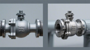
Seat Materials
In ASME Class 150 to 300 normal-temperature natural gas lines, Virgin PTFE, leveraging a low surface friction coefficient of 0.04 to 0.10, maintains the Break to Open torque of a 4-inch floating ball valve within a 550 N·m range.
The tensile strength of virgin PTFE is roughly 25 MPa. When the pipeline operating temperature exceeds 120°C or the hydrostatic differential pressure hits 740 psi, the seat surface will experience Cold Flow plastic deformation of over 0.2 mm. Manufacturers will blend 15% to 25% glass fiber or carbon powder into the base PTFE resin, molding it into Reinforced PTFE (RPTFE) to resist deformation.
- Shore Hardness: Shore D hardness of RPTFE increases from 55 for pure polymer to between 65 and 70.
- Pressure Limit: Yield strength is boosted by 30%, permitting the maximum system operating temperature to extend to 204°C.
- Torque Penalty: The introduction of glass fiber bumps the dry friction coefficient up to 0.12, requiring a 15% to 20% increase in the operating torque for a similarly sized trunnion ball valve.
Long-distance crude oil and refined product mainlines frequently select nylon (Nylon 12 or Devlon V-API) as the primary sealing material for large-diameter trunnion ball valves. Devlon’s tensile strength reaches 80 MPa, capable of enduring the massive mechanical thrust generated by ASME Class 600 (1480 psi working pressure) and even Class 900 (2220 psi).
According to the ASTM D638 test specification, Devlon V-API’s elongation at break is rated at 15% in a 23°C environment. Highly rigid physical properties demand that the Inconel springs behind the trunnion ball valve provide at least 250 lbs of pre-load thrust, forcing the nylon seat to undergo microscopic deformation to conform to the 316 stainless steel sphere.
In steam injection or High-Pressure High-Temperature (HPHT) logging applications, Polyetheretherketone (PEEK) bridges the performance degradation gap of conventional thermoplastics. PEEK polymer boasts a melting point as high as 343°C, exhibiting tremendous mechanical dimensional stability in the ultra-high-pressure environments of ASME Class 1500 (3705 psi) and Class 2500 (6170 psi).
- Surface Hardness: PEEK’s Rockwell M hardness hits 100, and tested compressive strength is 130 MPa.
- Friction Coefficient: When paired with an unpolished ball, the dry friction coefficient climbs to the 0.15 to 0.25 range.
- Torque Surge: When a 10-inch Class 1500 trunnion ball valve utilizes PEEK seats, the set value for the matched rack and pinion actuator’s output torque must leap above 12,500 N·m.
At a 1480 psi pressure differential in a 6-inch Class 600 floating ball valve, the contact surface specific pressure of the 152 mm diameter ball against the PEEK seat exceeds 5000 psi.
Compression exceeding the high-polymer material’s yield limit will leave permanent indentations 0.5 mm deep on the seat cross-section, destroying the component’s original cylindricity. Trunnion ball valves transfer 90% of the axial fluid thrust through upper and lower pivot supports; the PEEK insert within the metal skeleton bears only the 180 lbs of spring pre-load and limited Piston Effect auxiliary thrust.
Process pipelines containing abrasive solid particles (such as ore sand, coal dust, or catalysts) necessitate API 6D valves to abandon soft polymer seals in favor of Metal-to-Metal hard sealing configurations. The surfaces of the ball and metallic seats must be coated with a 0.2 mm thick Tungsten Carbide or Chromium Carbide layer via the High-Velocity Oxygen Fuel (HVOF) spraying process.
The Vickers Hardness (HV) of a tungsten carbide surface coating reaches a staggering 1200 to 1500, far exceeding the 800 HV of common quartz sand particles. This hardened layer permits valve components to execute 2000 full open/close cycles in 400°C high-temperature fluid carrying 5% solid impurities without sustaining deep scratches.
The mechanical friction coefficient of a hard-sealed trunnion ball valve approaches 0.3. Engineering designs typically require pairing 8-inch metallic seat products with massive scotch yoke pneumatic actuators to output a Break to Open (BTO) torque of 6500 N·m. The API 6D specification relaxes the factory leakage acceptance criteria for metallic seals to ISO 5208 Rate D or Rate C.
- Rate A Class: Resilient soft-seated valves must achieve an absolute zero leakage state of 0 drops/minute.
- Rate D Class: An 8-inch metal-seated valve under 1630 psi hydrostatic pressure is permitted 24 ml of trace liquid leakage per minute.
- Vacuum Lapping: Before assembly, the ball and metal seats must undergo 48 hours of paired mechanical Lapping to polish the contact surface roughness down to Ra 0.08 µm.
For standard water or low-pressure gas services, 75 Shore A hardness Fluorocarbon rubber (FKM / Viton) O-rings are chosen. Their applicable lower operating temperature limit is -29°C, and they cap out at a physical limit of 200°C.
During accidental rapid depressurization of high-pressure natural gas lines, gas dissolved in the pores of rubber polymers expands rapidly, causing Explosive Decompression. The NACE MR0175 standard dictates that high-pressure gas well valves must employ NORSOK M-710 certified Anti-Explosive Decompression (AED) HNBR or dense FKM rubber with 90 Shore A hardness.
Operating temperatures of pipelines at Liquefied Natural Gas (LNG) receiving terminals can plummet sharply to -162°C or even -196°C. All conventional rubber O-rings will lose elasticity and shatter into irregular fragments after crossing their Glass Transition Temperature.
Deep cryogenic conditions at -196°C switch to Polychlorotrifluoroethylene (PCTFE / Kel-F) as the primary seal material, embedding a spring-energized Lip Seal at the back of the metal seat skeleton. The lip seal jacket is machined from Teflon, internally housing a U-shaped spring made of Elgiloy cobalt-chromium-nickel alloy.
Elgiloy alloy springs maintain a constant 120 lbs of expansion force in an ultra-low-temperature -196°C liquid nitrogen environment, prying open the lip of the Teflon jacket to press tightly against the metal groove wall, maintaining a zero leakage state under a Class 300 pressure differential. PCTFE material exhibits a 2.5% volumetric shrinkage rate under cryogenic conditions, so the CNC machining tolerance of the seat skeleton must pre-compensate for 1.5 mm of physical shrinkage to prevent the ball from seizing at low temperatures.
The API 607 7th edition fire test clause examines the failure response process of various seat materials under simulated fire furnace temperatures from 760°C to 980°C. Within 15 minutes of ignition, nylon or PEEK soft-seal inserts undergo a complete physical phase transition—softening, melting, and ultimately carbonizing into ash.
The 316 stainless steel wave springs behind a trunnion ball valve retain 80% of their mechanical yield strength even at 760°C, continuing to push the metal seat skeleton, bereft of its polymer seal layer, toward the ball surface. When forced cooling is followed by a 30 psi low-pressure hydrostatic test, the leakage of a 6-inch valve must be held within a strict 240 ml per minute tolerance threshold to earn third-party fire-safe certification.
Pressure Performance
Under the API 6D standard, ball valve pressure ranges are classified from Class 150 to Class 2500 per ASME B16.34.
Floating ball valves rely on upstream fluid pressure to push the ball towards the downstream seat, with the thrust magnifying proportionally to the pipeline cross-sectional area.
Taking an NPS 6 Class 300 valve as an example, at an operating pressure of 740 PSI, the downstream seat must unilaterally withstand approximately 21,000 lbs of thrust.
Trunnion ball valves secure the ball via upper and lower trunnions, utilizing springs to push the dynamic seat to achieve sealing.
When pipeline working pressure exceeds Class 300 (approx. 740 PSI) or the size grows larger than NPS 6, a trunnion structure can successfully keep the stress on polymer materials within their yield strength.
Transmission & Load-Bearing
According to the pressure-temperature ratings established by the ASME B16.34 standard, at a normal temperature of 38 degrees Celsius (100 degrees Fahrenheit), the internal working pressure of Class 600 pipelines reaches 1480 PSI. When a ball valve cuts off flow, the blocked media exerts a horizontal physical thrust against the cross-section.
In the mechanical model of a floating structure, the ball itself acts as a piston bearing the pressure. Take a 4-inch nominal size API 6D floating ball valve as an example: its internal bore diameter is about 3.94 inches. The wetted cross-sectional area contacting the fluid is roughly 12.19 square inches. At 720 PSI pipeline pressure, the fluid applies over 8700 pounds of horizontal thrust to the ball.
The non-metallic seat ring is the sole pressure-bearing component handling this 8700-pound thrust. The actual contact area between the ball surface and the PTFE seat is merely a few square inches. When 8700 lbs of load is entirely concentrated on a narrow sealing ring, internal compressive stress often breaches PTFE’s normal-temperature yield limit of roughly 2000 PSI. The material will subsequently suffer cold flow extrusion along the gaps in its metal support groove.
The friction coefficient between polymer surfaces and a polished stainless steel ball generally ranges from 0.04 to 0.10. An 8700-lb normal force creates up to 870 lbs of sliding friction at the sealing interface. When driving the ball through its 90-degree rotation, the stem must overcome this frictional resistance. Operators typically must equip gearboxes or large pneumatic actuators to deliver sufficient torque.
- Thrust Origin: Hydrostatic pressure generated by the upstream pipeline media.
- Load-Bearing Component: Downstream single-sided non-metallic polymer seat ring.
- Displacement Data: The ball slides 0.5 to 2 mm in the direction of the flow.
- Torque Performance: Operating resistance spikes linearly with the pressure differential across the pipeline.
A 10-inch Class 900 trunnion ball valve faces a maximum working pressure up to 2220 PSI. The total thrust exerted by internal fluid on a closed 10-inch ball approaches 174,000 lbs. No conventional polymer seat can withstand 78 tons of physical compression without structural failure.
The top stem and bottom trunnion form extremely robust load-bearing anchors. The massive 174,000-pound fluid load completely bypasses the seat assemblies. The forged steel ball transfers the thrust it receives directly to the sliding bearings at its top and bottom. The internals of these bearings typically employ metal-backed PTFE or sintered bronze materials, boasting radial compressive strengths up to 40,000 PSI.
The ball consistently rotates fixed along a vertical axis. Sealing action is accomplished by independent floating seat rings on both sides. Engineers install Inconel X-750 helical or Belleville springs behind the seats. This spring array supplies a constant pre-load of 50 to 100 PSI, ensuring that even at 0 PSI line pressure, the seats snugly hug the ball surface to form an initial seal.
- Initial Pre-load: Inconel wave springs provide 50-100 PSI baseline thrust.
- Piston Effect: Pipeline pressure proportionally amplifies the seat’s compressive force by area.
- Primary Subject of Pressure: Top and bottom trunnion bearings absorb over 90% of the fluid load.
- Deformation Control: Polymer seats only bear the minimum compressive force needed to maintain the seal.
Once fluid enters the valve body, it creates a Piston Effect on the back of the seat ring. The outer diameter of the seat ring is larger than its inner sealing face diameter, creating a cross-sectional area differential. The pipeline media pressure acts upon this excess area, driving the seat forward toward the ball. The higher the pipeline pressure, the stronger the seat’s thrust against the ball, achieving pressure-adaptive sealing compensation.
The API 6D specification dictates that the stem must feature a blowout-proof design. The stem employs a bottom-entry structure, inserted from the valve’s internal cavity. An integral shoulder at the base of the stem gets caught against a mechanical step inside the valve body. When internal fluid pressure hits 1480 PSI, physical thrust presses the stem shoulder even tighter against the thrust washer, preventing it from blowing out of the high-pressure valve body.
The rotational friction coefficient within the trunnion’s self-lubricating bearing is kept extremely low. A metal bearing lined with PEEK has a friction coefficient of around 0.15. Even under a colossal 78-ton radial load, rotational resistance remains within a reasonable range. The operating torque required for a 10-inch Class 900 trunnion ball valve is roughly 15,000 inch-pounds, requiring only a standard scotch yoke pneumatic actuator for smooth operation.
The physical phenomenon of excess pressure accumulating in the central valve body cavity is particularly common in liquid transmission lines. When a closed ball valve traps liquid hydrocarbons inside, a 50°F rise in ambient temperature forces the fluid volume to expand by approximately 3%. In an absolutely sealed metal cavity, volumetric expansion can push internal cavity pressure above 3000 PSI, far exceeding the 1480 PSI safety threshold set for Class 600.
- Trigger Condition: Cavity pressure exceeds upstream line pressure by 100 to 200 PSI.
- Mechanical Action: High pressure overcomes rear spring pre-load to push the upstream seat open.
- Relief Path: Trapped high-pressure fluid bleeds back into the upstream pipeline system.
- Recovery State: Once cavity pressure drops, the spring immediately pushes the seat back to the closed position.
When large pump stations suddenly trip, pressure waves traveling at 4000 ft/sec are generated inside the pipeline. Engineers select forged ASTM A105 or A350 LF2 carbon steel materials for three-piece valve bodies. The various valve body sections are bolted together using high-strength ASTM A193 B7 studs.
The B7 bolts installed on the flange faces are pre-tensioned by hydraulic wrenches to a yield stress exceeding 100,000 PSI. Extremely high bolt tensile force ensures that when the segmented valve body endures 1480 PSI of internal high pressure and water hammer shock waves, no minute gaps capable of causing media leakage will form between the mating surfaces.
Pressure & Size
In engineering practice, the product of operating pressure and pipeline cross-sectional area constitutes the absolute physical load borne by internal valve components. A NPS 2 ball valve operating at 285 PSI versus a NPS 24 ball valve operating at 1480 PSI represent orders-of-magnitude differences in material yield strength requirements.
The mechanical architecture of a floating ball valve strictly confines its application to the intersection of small diameters and low-to-medium pressures. As long as pipeline sizes stay between NPS 1/2 and NPS 4, PTFE seats can completely absorb the thrust generated by Class 150 to Class 300 working pressures.
The moment either size or pressure breaches the threshold, physics compel engineers to change valve types. Consider a NPS 8 floating ball valve: its pipe cross-sectional area is about 50 square inches. At the 740 PSI maximum cold working pressure mandated by Class 300, the upstream thrust surges to a massive 37,000 lbs.
A staggering 18.5 tons of hydrostatic thrust would entirely focus on the downstream single-sided polymer sealing ring. The tensile strength of PTFE at 73°F (approx. 23°C) is a mere 2500 to 3000 PSI. A 37,000-lb load would instantaneously crush a non-metallic seat ring that is only 0.5 inches thick.
| Valve Body Structure | ASME Pressure Class | Applicable Size (NPS) | Max Cold Working Pressure (PSI) | Seat Material Requirement |
|---|---|---|---|---|
| Floating | Class 150 | 1/2″ – 8″ | 285 | RPTFE (Reinforced PTFE) |
| Floating | Class 300 | 1/2″ – 6″ | 740 | RPTFE / Nylon 12 |
| Floating | Class 600 | 1/2″ – 2″ | 1480 | Devlon V / PEEK |
| Floating | Class 900 | 1/2″ – 1″ | 2220 | PEEK |
The trunnion is internally equipped with a stainless steel composite bearing lined with PTFE. When bearing approximately 300,000 lbs of thrust generated by an NPS 16 line at 1480 PSI, the bearing still maintains a low friction coefficient below 0.15.
When pipe bores expand to NPS 20 and above, long-distance natural gas pipelines universally adopt Class 600 or Class 900 high-pressure designs. An NPS 24 Class 900 trunnion ball valve has an internal bore diameter of 23.25 inches. The physical load applied by the fluid to the closed ball tops 940,000 lbs (roughly 426 tons).
Under a brutal 426-ton load, the spring-loaded dynamic seats only need to supply a tiny pre-load to maintain a seal. Dozens of Inconel 718 cylindrical helical springs installed at the rear offer around 80 PSI of base seating pressure. The Piston Effect leverages the pipeline’s own 2220 PSI pressure to tightly pack the downstream seat against the fixed ball’s surface.
- Load Transfer: Trunnion systems absorb 100% of hydrostatic fluid thrust, shielding seats from crushing forces.
- Friction Torque: Sliding bearings lock operating torque within rated limits, accommodating standard actuators.
- Seal Compensation: Dynamic seats achieve adaptive conformity through dual forces of springs and fluid pressure.
- Material Downgrade: Large-diameter high-pressure valves can still safely utilize standard thermoplastics like Nylon as primary seals.
Deepwater fluid media and high-pressure gas injection systems routinely operate in the extreme environments of Class 1500 and Class 2500. For NPS 10 Class 1500 piping, max working pressure skyrockets to 3705 PSI. Fluid velocity typically exceeds 60 ft/sec. Fearsome impact forces coupled with extremely high internal pressures impose grueling casting or forging requirements on valve body wall thickness.
Engineers utilize ASME B16.34 formulas to mandate a minimum valve body wall thickness of at least 1.87 inches for NPS 10 Class 1500 valves. Valve bodies generally use ASTM A350 LF2 low-temperature carbon steel forgings, verified via ultrasonic non-destructive testing to eliminate microscopic internal cracks. High-strength forged steel wards off massive hoop stresses born from 3705 PSI of internal pressure.
| Valve Body Structure | ASME Pressure Class | Applicable Size (NPS) | Max Cold Working Pressure (PSI) | Mechanical Load-Bearing Component |
|---|---|---|---|---|
| Trunnion | Class 600 | 2″ – 60″ | 1480 | Forged steel upper/lower trunnions & sliding bearings |
| Trunnion | Class 900 | 2″ – 48″ | 2220 | Forged steel upper/lower trunnions & sliding bearings |
| Trunnion | Class 1500 | 2″ – 24″ | 3705 | High-strength alloy steel trunnion / Belleville springs |
| Trunnion | Class 2500 | 2″ – 12″ | 6170 | Metal-to-Metal Tungsten Carbide coated hard seal |
An NPS 2 Class 150 floating ball valve requires an opening torque of a mere 300 inch-pounds. Simply equipped with an 8-inch lever, operators can effortlessly execute a 90-degree turn applying less than 40 lbs of pull.
When scaling up to an NPS 12 Class 900 trunnion ball valve, required operating torque busts through 80,000 inch-pounds. This totally eclipses human physical limits. A worm gear reducer with an 80:1 ratio or higher must be mounted atop the stem. Even applying 50 lbs of force to the handwheel requires hundreds of revolutions to fully open or close the valve.
For Emergency Shutdown (ESD) scenarios in long-distance pipelines, API 6D specifications demand high-power scotch yoke pneumatic or hydraulic actuators. The inner bore of the actuator cylinder commonly reaches 16 to 24 inches. When supplied with 100 PSI instrument air, the cylinder piston outputs over 200,000 inch-pounds of instantaneous breakaway torque, forcibly severing high-pressure flow in an NPS 16 Class 600 pipeline within 5 seconds.
- Small Diameter/Low Pressure (NPS 2-4, Class 150-300): Physical lever operation, exceptionally low torque.
- Medium Diameter/Medium Pressure (NPS 6-10, Class 300-600): Gearbox handwheel required, smooth torque.
- Large Diameter/High Pressure (NPS 12-36+, Class 600+): Pneumatic/hydraulic drive mandatory, massive torque.
- Torque Safety Factor: During sizing calculations, actuator output torque must reserve at least a 1.25x safety margin.
An NPS 4 Class 300 flanged-end floating ball valve weighs roughly 150 lbs, easily hauled and installed by two workers. An NPS 36 Class 900 three-piece trunnion ball valve weighs over 45,000 lbs (roughly 20 tons).
Hoisting a 20-ton valve demands specialized mobile cranes. Cast or welded lifting lugs must be provided on the valve body. Lug cross-sections are engineered according to ASME B30.20 standards, ensuring a safety factor no less than 3 when bearing the valve’s dead weight plus dynamic loads caused by gravitational acceleration.
To battle the system’s high pipeline pressure, flange thickness and bolt sizes at both ends balloon accordingly. NPS 24 Class 600 flanges are 4.5 inches thick. Twenty-four 1.875-inch diameter bolt holes dot the flange perimeter. Installation necessitates hydraulic tensioners to torque ASTM A193 B7 high-strength double-ended studs to their rated pre-load.
Design pressures on long-haul oil and gas lines shift based on topographical elevations. In valleys where pipelines drop over 1000 feet, hydrostatic head pressure stacks onto the rated operating pressure. An NPS 16 pipeline that operates fine with Class 300 valves across flat plains must upgrade to Class 600 trunnion-mounted valves featuring 1.5-inch wall thicknesses right at the valley bottom pump station inlet.
Bleeding & Double Block
When a standard NPS 12 pipeline ball valve is closed, it features two independent dynamic seat assemblies upstream and downstream. These dual polymer seats each rely on 24 to 36 rear-mounted Inconel X-750 springs to provide roughly 75 PSI of initial mechanical thrust.
At the absolute bottom of the valve body, a drain hole (usually 1/2-inch or 3/4-inch NPT threaded) connects to a high-pressure needle valve. As operators rotate the main valve 90 degrees to fully closed, upstream 1480 PSI high-pressure natural gas is blocked by the primary seat. Opening the bottom needle valve clears out about 1.5 gallons of residual media trapped between the metal ball and the valve body.
API 6D DBB Testing Protocol: Under 110% of rated pressure, apply fluid hydrostatic pressure alternately to each seat end with the bleed valve wide open. Observe cavity leakage; zero droplets are required prior to shipment.
Field maintenance engineers exploit this drained, zero-pressure cavity to ensure safe isolation during live work. An NPS 24 oil pipeline flowing fully loaded at 15 ft/sec subjects a single-sided flange to roughly 600 tons of thrust. DBB architecture guarantees that even if the upstream single-sided PTFE seal ring suffers 0.1 mm of minor wear, seeping media is safely shunted down the bleed line into an atmospheric recovery tank.
Once liquid hydrocarbons are locked into this isolated cavity, they display extreme physical sensitivity to ambient temperature swings. Taking Texas summer outdoor pipelines as an example: early morning 60°F trapped crude oil undergoes roughly 4.5% volumetric expansion when the mid-day metal pipe wall heats up to 130°F.
An NPS 16 Class 600 ball valve holds roughly 3.2 gallons in its cavity; expanding liquids lack any compressible space. According to fluid bulk modulus calculations, every 1°F temperature rise rockets hydrostatic pressure up by approximately 75 PSI within the sealed cast steel void. Just a few hours of sun exposure will catapult internal pressure from 1480 PSI to well over 4000 PSI.
To bleed off abnormal high pressure, engineers standardize self-relieving seats featuring Single Piston Effect (SPE) tech. The upstream face and rear face of an SPE seat have an area differential of roughly 15%. Once internal cavity fluid pressure overtakes upstream line pressure by 100 to 150 PSI, physical thrust completely overpowers the 75 PSI pre-load of the rear Inconel springs.
- Trigger Threshold: Cavity pressure overtakes line pressure by roughly 133% or more.
- Mechanical Action: High pressure forces the 45-lb polymer seat ring away from the ball surface by roughly 0.05 inches.
- Relief Path: Around 0.2 gallons of over-pressurized crude trickles backwards through tiny crevices into the main upstream line.
- Reset Sealing: The instant cavity pressure drops to safe levels, mechanical springs aggressively smack the seat back against the ball.
The API 6D standard defines a Double Isolation and Bleed (DIB-1) configuration using dual Double Piston Effect (DPE) seats. In a DPE design, whether media pressure stems from the upstream line or internal cavity, fluid thrust jams the seats tightly against the ball.
For an NPS 20 pipeline block valve equipped with DPE seats, both upstream and downstream flanks utilize 2220 PSI pipeline pressure for self-energized sealing. Since the cavity lacks the SPE seat’s auto-relieving luxury, manufacturers are forced to drill an extra hole through 2.5 inches of thick metal valve body wall.
External Relief Solution: Mount an independent spring relief valve on the valve body flank, set to a popping pressure of 1600 PSI. Expanding media is bled off through a 0.5-inch impulse line straight into the flare system.
Blending SPE and DPE components physically gives birth to the DIB-2 architecture for trunnion valves. An NPS 10 DIB-2 valve stations a standard SPE relief seat upstream and pairs it with a rugged DPE isolation seat downstream. When fluid scours the pipeline, the upstream side maintains the physical convenience of self-relief.
Under 1000 PSI operating pressure, if the upstream SPE sealing ring fails due to a 0.5 mm deep scratch inflicted by trapped quartz sand, high-pressure natural gas floods the cavity. At this moment, the downstream DPE seat utilizes a massive 1000 PSI cavity pressure Piston Effect to brace itself dead against the polished ball, clamping the leakage rate under 10 ml per minute.
Valve Size
Under the API 6D specification, valve size directly delineates the physical boundary between trunnion and floating ball valves. Floating valves rely on fluid pushing the ball to create a seal, a physical limit that generally stops dead at 6 inches (DN150).
Beyond this diameter, fluid thrusts of Class 300 and above pressures will instantly crush PTFE and other non-metallic seats.
Trunnion ball valves support the ball using upper and lower pivot shafts, forcing the metal valve body to shoulder fluid thrusts. Their starting point is 2 inches (DN50), and they can easily scale up to 60 inches (DN1500) and beyond.
8 inches is the definitive watershed: pipelines 8 inches and above exclusively deploy trunnion valves, while 2 to 6-inch sizes pick between the two based heavily on pressure classes.
Size Limitations
When pipeline sizes grow from 2 inches to 8 inches, the ball’s fluid-facing cross-sectional area inflates geometrically. Under a Class 600 pressure rating, internal line pressure hovers around 10 MPa. An 8-inch ball in a fully closed position endures over 35 tons of media thrust.
Such staggering physical thrust is channeled entirely into a downstream PTFE or Nylon seating face barely a few millimeters wide. The compressive yield strength of PTFE typically ranges from 14 MPa to 25 MPa. The moment thrust breaches a soft seat’s mechanical load-bearing ceiling, the polymer suffers irreversible cold flow deformation.
Once a seat undergoes excessive compression deformation, the sealing face fails, spawning internal pipeline leaks. In conventional gathering network design codes across North America’s Permian Basin, the max diameter for soft-seated floating valves is explicitly capped at 6 inches. If operating pressures rise to Class 900 (roughly 15 MPa), the floating valve usage ceiling is aggressively squashed below 2 inches.
Engineers draft procurement frameworks based on specific physical boundary data during selection:
- Doubling the bore diameter quadruples the force-bearing area.
- Devlon V-API material maxes out at roughly 140 MPa compressive strength.
- Massive solid balls drastically increase bottom friction and wear.
- Thrust transformed into friction demands gargantuan actuators.
A 2-inch carbon steel ball weighs under 2 kg, possessing a degree of suspension within fluid. A solid 24-inch A105 carbon steel ball tips the scales past 1.5 tons. Deprived of bottom support, a heavy-duty ball left to constant gravity will subject the bottom seat to an uneven load, rapidly accelerating single-sided wear.
Massive thrust piggybacked onto massive weight poses absurd torsional strength demands on stems. For a Class 300 6-inch floating ball valve, break-to-open friction torque can blast to 1500 N·m. Merely overcoming this resistance to rotate the ball demands abnormally thick stem diameters, swelling the top flange pad and packing gland into bloated structures.
A trunnion ball valve’s design logic mechanically decouples fluid load-bearing from the sealing action. The ball is outfitted with high-strength metal fixed shafts and low-friction bearing assemblies top and bottom. Tens or even hundreds of tons of upstream fluid thrust are entirely absorbed by these two metal bearings and a thick-walled forged steel body.
The ball solely performs a 90-degree rotation within the valve body, possessing zero horizontal displacement. The downstream seat no longer acts as a backstop against ball displacement, relying strictly on Inconel 718 cylindrical helical springs planted behind it to provide a few hundred Newtons of initial pre-load. Whether dealing with a 12-inch or 48-inch pipe, the specific pressure endured by the seat sealing face is kept tightly within the material’s safe yield curve.
This mechanical decoupling design breeds multiple concrete parameter optimizations in engineering application:
- Thrust is completely shifted to top and bottom metallic trunnions.
- Piston Effect establishes an active sealing grip.
- Friction stems from bearings, not the entire ball surface.
- DBB (Double Block and Bleed) functionality becomes achievable in large sizes.
The Trans-Alaska Pipeline System (TAPS), stretching roughly 1287 km, extensively deployed 48-inch API 6D fully welded pipeline ball valves on its main artery. Confronted with deep-freeze Arctic temperatures and 8 MPa operating pressures, a single 48-inch trunnion ball valve hits nearly 40 tons in weight. Only a trunnion structure can ensure this mammoth ball is smoothly driven by hydraulic actuators amid extreme temperature swings.
Deepwater gas transmission platforms in the Texas Gulf of Mexico commonly utilize sizes ranging from 10 to 24 inches. Facing ultra-high-pressure Class 1500 (roughly 25 MPa) conditions, high-strength Duplex Stainless Steel (Duplex 2205) trunnion ball valves become standard spec. High-pressure gas drives the seat piston assemblies, forcing PEEK sealing rings tightly and evenly onto balls anchored to their bearings.
When projects involve pipeline Pigging operations, internal geometric tolerances are notoriously strict. API 6D specifications demand that full-port ball valve bores perfectly match the pipeline’s inside diameter, tolerating absolutely zero reduced-port throttling. For 36-inch main gas transmission lines, the massive voids inside trunnion valves are outfitted with drain and vent ports, allowing operators to flush out accumulated debris prior to pigging.
Violent pressure swings are commonplace in mega-pipeline networks. Single or Double Piston Effect seat designs built into trunnion valves automatically relieve pressure when cavity pressure outpaces line pressure by 1.33 times due to rising temperatures. Across major above-ground tank farms using 24-inch and larger headers, cavity relief functions successfully prevent physical ruptures triggered by vaporizing liquid trapped inside valves.
API 6D specifications impose clear digital accessory mandates on specific pipe sizes:
- Pigging restricts bore tolerances to within a few millimeters.
- Cavities exceeding certain volumes are mandated to possess relief valves.
- 8-inch and up feature standardized seat emergency sealant injection ports.
- Large sizes default to gearboxes or power actuators.
Procurement budgets trace a steep upward curve once bores surpass 8 inches. A 2-inch Class 300 manual floating ball valve typically costs a few hundred dollars. An equivalently rated 20-inch trunnion valve sporting a gas-over-oil actuator, due to massive forging, Inconel springs, and complex testing regiments, shoots the total price tag into the tens of thousands.
Maintenance costs also mutate structurally alongside expanding size. When a small floating valve leaks, engineers generally unbolt it from the flanges, discard it, and slap in a new valve. Trunnion valves 24 inches and over mostly lean on top-entry or fully welded body designs, empowering technicians to pop the top bonnet for repairs while the pipeline remains pressurized and flowing.
Large Size Expansion
API 6D lays down brutal physical and mechanical mandates for fluid shutoff once pipeline bores cross the 12-inch (DN300) mark. In high-pressure Class 900 (roughly 15 MPa) long-haul pipelines, the Trunnion structure bears all media thrust. Solid metal cylinders at top and bottom ends are firmly lodged into specialized bearing blocks deep inside the forged steel valve body.
Up to hundreds of tons of blind line thrust are entirely offloaded onto the high-strength pressure-bearing shell. A solid 36-inch (DN900) stainless steel ball weighs over 4.5 tons; merely sitting idle in fully open or closed positions, its own gravitational weight would crush bottom non-metallic sealing rings. A top stem synchronized with a bottom trunnion ensures that this heavy-duty metal sphere maintains dead center within its physical cavity.
Utilizing self-lubricating PTFE metal-composite bearings restricts the rotational friction coefficient of a 4.5-ton ball strictly to between 0.05 and 0.08.
Trimming the friction coefficient keeps massive valve breakaway torques under extreme pressure differentials firmly within the output bracket of hydraulic actuators (roughly 80,000 N·m). Thrust is no longer weaponized against downstream seats, and physical squeezing forces suffered by the sealing face are confined to the pre-load of rear Inconel 718 cylindrical helical springs. This pre-load is typically locked dead at 0.5 MPa, precisely fulfilling bubble-tight sealing standards at low pressures.
Once pipeline sizes balloon to 48 inches (DN1200), ordinary two-piece cast valve body walls can no longer endure thousands of tons of pipeline tensile and bending thermal stress. Mainline block valves on North America’s Keystone Pipeline universally utilize three-piece completely forged or Fully Welded structures. ASTM A105 carbon steel forgings stubbornly maintain Charpy impact toughness test values over 27 Joules even plunged to minus 46 degrees Celsius.
- Diameters 24 inches and above feature standardized Emergency Sealant Injection Fittings completely independent of the primary seal.
- The absolute lowest point of the valve body is fitted with a drain valve not less than 2 inches in bore to clear rust and debris from long-haul lines.
- The top anti-blowout stem enforces triple isolation sealing utilizing dual-duplex steel O-rings combined with graphite fire-safe packing.
- Main pressure-bearing zones of ball valves larger than 40 inches undergo 100% full-weld Ultrasonic Testing (UT).
In Class 600 (roughly 10 MPa) natural gas lines, the Piston Effect weaponizes upstream media pressure into supplemental mechanical thrust. The higher the media pressure, the harder the hundreds of kilos of thrust produced by the rear-vs-front area differential shoves PEEK sealing rings against the nickel-plated ball.
API 6D DPE (Double Piston Effect) seats allow media to push the piston rings from both upstream and downstream directions simultaneously, forging two independent seals.
The central cavity volume of a 42-inch ball valve exceeds 150 liters; liquid hydrocarbons trapped inside will vaporize under a baking sun, instantly rocketing internal pressures to 1.5 times the rated pipeline limit. SPE (Single Piston Effect) seats autonomously pop open via spring compression to vent pressure into the line the moment the differential breaches 1.33 times.
Vast flow passages demand insanely high surface finishing precision to slash Pressure Drop. The flow coefficient (Cv value) of a 60-inch (DN1500) full-bore ball valve in the fully open state reaches 330,000 gpm. Fluid glides smoothly through ball passages coated with a 25-micron Electroless Nickel Plating (ENP) anti-corrosion layer, matching the frictional resistance of an equivalent length of straight pipe.
Pipeline Pigging operations wield zero tolerance for a valve’s internal geometric tolerances. North American oil and gas operators mandate that the bore inside a 36-inch ball valve must clock in at exactly 863.6 mm, with a full-stroke cross-sectional error not exceeding ±1.5 mm. A protruding metal ledge will lethally jam a smart pig worth tens of thousands of dollars and stretching over 3 meters long.
Procuring power actuators devours over 40% of the total valve price tag once bores stretch past 24 inches. High-pressure gas lines in remote deserts utilize Gas-Over-Oil Actuators, siphoning 10 MPa natural gas right out of the pipeline as their drive source. This entirely bypasses the colossal engineering budget required to string hundreds of kilometers of power cables to unmanned remote valve stations.
An entirely kitted-out 48-inch Class 600 fully welded ball valve strapped with its hydraulic system spans over 4 meters in length, width, and height, hitting a total assembled weight of 38 tons.
Installing fluid control equipment weighing tens of tons commands massive crawler cranes and pouring reinforced concrete foundations armed with embedded plates right on site. Natural gas gathering stations in the Middle Eastern Rub’ al Khali desert—desperate to trim field flange bolt torque-checking and future upkeep workloads—will have 2-meter Pup Pieces butt-welded directly to both valve ends right from the factory.
Selection Comparison
An ordinary carbon steel floating ball valve weighs barely 15 kg; pipeline workers can easily wrestle through flange installation by hand without needing hoisting equipment.
Swap that exact size for a Trunnion ball valve, and extra bottom metal support bearings paired with dual-side spring assemblies blast its total weight past 35 kg. On the purchasing sheet, a 2-inch ASTM A105 forged trunnion valve generally commands a 40% to 60% premium over a floating valve, ballooning initial plant construction overhead.
When pipeline operating pressures upgrade to high-pressure specs, a 3-inch (DN80) pipe exposes entirely different material load-bearing extremes. A Class 1500 (roughly 25 MPa working pressure) fluid imposes over 11 tons of horizontal thrust onto a 76.2 mm diameter stainless steel ball.
PTFE non-metallic seat materials subjected to mechanical squeezing beyond 15 MPa suffer irreversible cold-flow deformation within 72 hours. To halt the sealing face from disintegrating, high-pressure 3-inch lines mandate trunnion structures, dumping up to 11 tons of thrust right onto forged metal bodies boasting yield strengths exceeding 200 MPa.
For 4-inch (DN100) oilfield gathering systems, automated actuator requirements heavily dictate base valve architecture. Overcoming the sheer 1200 N·m breakaway frictional resistance of a 4-inch Class 300 (roughly 5 MPa) floating ball valve necessitates a massive 14-inch bore pneumatic actuator.
Merely cracking open a 4-inch floating valve strapped to a gargantuan cylinder devours over 25 liters of 0.5 MPa compressed air per stroke. Once swapped out for a trunnion valve of equal size, friction is cornered onto a bearing surface barely millimeters wide, forcing operating torque to violently plummet under 400 N·m.
| Evaluation Parameter Dimension | 4-inch Class 150 Floating Valve | 4-inch Class 150 Trunnion Valve | 6-inch Class 600 Floating Valve | 6-inch Class 600 Trunnion Valve |
|---|---|---|---|---|
| Test Torque | 180 Nm | 95 Nm | 4500 Nm | 850 Nm |
| Actuator Type | Standard lever or small gearbox | Easily operated via lever | Requires extra-large hydraulic pusher | Standard pneumatic scotch yoke actuator |
| Bare Valve Weight | 45 kg | 85 kg | 320 kg | 580 kg |
| Applicable Media | Clean low-pressure water, nitrogen | Crude oil, sandy gas | Exceeds limits of soft seal materials | Multiphase flow, high-pressure natural gas |
Slashing operating torque shrinks the pneumatic actuator for a 4-inch pipeline down to an 8-inch bore cylinder, shaving over $2000 off the automation control package procurement cost for each valve.
Once bore sizes hit 6 inches (DN150), crude inside the pipeline runs at 5 meters per second, packing ferocious fluid kinetic impacts. A trunnion design exploits a high-strength ASTM A350 LF2 forged steel body to smoothly transmit up to 15 tons of fluid kinetic energy right into the foundation supports.
Adhering to Double Block and Bleed (DBB) technical mandates baked into API 6D specifications, long-haul mainlines exceeding 8 inches (DN200) exclusively roll with trunnion valves. Maintenance crews utilize a bottom 1/2-inch NPT threaded port to entirely flush out 15 liters of trapped water from a heavy valve’s cavity, facilitating live online zero-pressure testing.
For cross-border gas pipelines 12 inches (DN300) and above, internal physical designs upgrade from DBB to Double Piston Effect (DPE). When pressure differentials hit a pre-set 1.5 MPa threshold, independent springs force Polyetheretherketone (PEEK) seats flush against nickel-plated trunnion-anchored balls.
- Mainline valves 10 inches and above sport stainless steel Sealant Injection fittings, ready to pump high-viscosity sealant into damaged seats to patch scratches.
- Inconel 718 cylindrical helical spring arrays loaded behind 16-inch pipeline seats output a constant 0.5 MPa pre-load, securing bubble-tight sealing at low pressures.
- Fully welded 24-inch ball valves boast independent adjustment capabilities; dual floating seats autonomously displace 2 to 3 mm horizontally to conform to metal balls.
Alaskan deep-freeze 24-inch (DN600) long-haul lines endure ferocious expansion and contraction stresses driven by extreme day/night temperature swings. Fully welded trunnion ball valves swallow up to 500 tons of pipeline axial pulling force, safeguarding massive valve body flange connections from even a micron of physical misalignment.
Daily maintenance protocols for giant valves warp entirely alongside sizing; a solid 36-inch (DN900) stainless steel ball alone hits over 5 tons dead weight. A trunnion design disperses 5 tons of dead weight across top and bottom metal load-bearing support plates locked in by 2-inch diameter ASTM A193 B7 high-strength bolts.
The EPA’s tight grip on Volatile Organic Compound (VOC) emissions caps the total fugitive emissions outside massive plant equipment, usually mandating they stay below 100 ppm. While a 2-inch floating valve skates by perfectly on ordinary V-ring PTFE packing, the tops of 24-inch valves demand 5 stacked layers of Grafoil rings compressed relentlessly by Belleville springs.
When orchestrating warehouse spare parts management for thousands of valves during early refinery setup phases, operators lean heavily towards standardizing everything above 4 inches strictly to trunnion architectures. Unified design specs eliminate over 150 distinct O-ring and spring SKU codes, drastically streamlining cross-border spare parts procurement over a grueling 20-year lifecycle.

")