
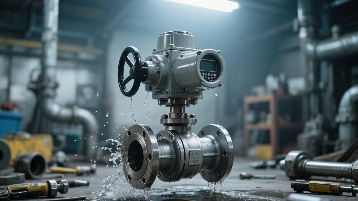
By tightening 4 to 8 flange bolts in a cross-pattern sequence and pairing them with a PTFE seal ring, the connection can withstand system pressures of up to 50 bar and keep the pipeline leak-tight.
The flange connection is extremely secure, and during routine maintenance, operators can remove the entire valve simply by unbolting it, without cutting the pipe.
This design can reduce maintenance downtime by about 60%, significantly improving both safety and service efficiency in hazardous chemical handling.
Leak Prevention
ISO 15848-1 requires VOC leakage from chemical valves to remain below 50 ppmv.
Under ASME B16.5, flange face roughness is controlled within 125-250 AARH. Combined with a CG-type spiral wound gasket, the joint can withstand Class 600 pipeline pressure (10.3 MPa).
The valve internals are tested in accordance with API 598 and use a disc spring-loaded V-ring PTFE packing set together with a fully enclosed seat design.
When media temperature fluctuates between -46°C and 260°C, the sealing gap remains within 0.01 mm, preventing both external leakage and internal cross-port leakage.
Stem Packing
ISO 15848-1 classifies valve VOC leakage into three levels: A, B, and C. Class A certification requires a helium leak detector probe positioned around the stem to measure leakage no greater than 2×10^-6 mg/s·m.
Conventional single-layer graphite rings cannot pass more than 100,000 open-close cycles. API 622 clearly defines the limits for physical wear and thermal weight loss of packing materials.
Multi-layer Chevron PTFE packing assemblies are typically stacked in 5 to 7 layers, with each V-shaped lip usually cut at an angle between 45 and 60 degrees.
When the gland follower applies downward mechanical force, the V-shaped lips expand inward and outward under compression. The inner lip seals tightly against the stem OD, while the outer lip grips the stuffing box bore.
Polymeric materials experience stress relaxation during repeated thermal cycling. At -46°C, conventional PTFE can shrink in volume by approximately 1.5% to 2.5%.
Live-loaded spring assemblies are used to compensate for the gaps created by dimensional change. Belleville washers are installed over the gland bolts.
Belleville springs forged from Inconel 718 offer extremely high fatigue strength. Even when stuffing box pressure fluctuates up to 10.3 MPa (Class 600), the spring assembly continues to maintain a stable preload.
Two opposed Belleville washers on each bolt can provide a continuous compensating torque of 50-100 N/m. Maintenance personnel do not need to routinely re-tighten the bolts by hand in the line area.
Anti-extrusion rings made of PEEK or carbon-fiber-reinforced material are installed at both the top and bottom of the packing set.
- When high-pressure fluid migrates upward along the stem, it can generate lifting forces of several thousand newtons.
- Pure PTFE is prone to cold flow deformation at temperatures above 200°C.
- The anti-extrusion rings prevent the soft polymer from being forced into the 0.1 mm clearance between the gland and the stem.
Stem surface roughness is tightly controlled within Ra 0.4 to 0.8 µm. Over-polishing prevents the packing from forming its initial lubricating film, while insufficient polishing accelerates wear of the V-rings.
Cylindricity tolerance is limited to within 0.012 mm. An eccentrically rotating stem can compress one side of the packing chamber during a 90-degree turn while creating a micro-gap on the other side.
The hardness differential between the stuffing box wall and the stem is selected according to reference values.
| Component | Typical Material Specification | Hardness / Friction Coefficient | Applicable Temperature Range |
|---|---|---|---|
| Stem | 17-4 PH precipitation-hardening stainless steel | HRC 38-45 | -196°C to 343°C |
| Gland Sleeve | ASTM A276 Type 316 | HB 217 | -60°C to 400°C |
| V-Ring Packing | 15% glass-fiber-reinforced PTFE | Dynamic friction coefficient < 0.1 | -50°C to 230°C |
| Spacer Ring | Laminated graphite rings | Fire-tested to API 607 | Above 500°C |
A bottom-mounted blow-out proof stem shoulder is retained on the inside of the valve body. Its outside diameter is 2 to 3 mm larger than the inside diameter of the stuffing box.
Even under 15 MPa line pressure, the fluid can only force the shoulder upward, where it becomes firmly trapped against the chamfer inside the body neck.
A thrust washer is also installed at the shoulder. It is typically made from modified nylon containing molybdenum disulfide lubricant and is about 1.5 mm thick.
The thrust washer absorbs the upward axial load on the stem and prevents galling between the metal shoulder and the metal body neck. Required operating torque is reduced by 15% to 20%.
In sour service with high concentrations of hydrogen sulfide (H2S), stem material is upgraded to Monel 400 or Incoloy 825 in compliance with NACE MR0175 / ISO 15156.
The nickel-alloy surface is nitrided to raise hardness to 800 HV. After 10,000 cycles of friction between the packing and the high-hardness stem, external leakage remains below 10 ppmv.
The ratio between stuffing box depth and stem diameter is carefully calculated. In standard designs, total packing height is kept at about 1.5 times the stem outside diameter.
If too many packing layers are used, the lower section cannot receive sufficient compressive force from the top. The bottom two V-rings remain in a relaxed state.
A lantern ring is used to separate the upper and lower packing sets. The hollow cavity is connected to an external leak-off port.
If the lower packing is penetrated by corrosive acid, the small amount of leaked media is diverted to a safe collection container, while the upper packing continues to block gas from escaping to atmosphere.
An anti-static plunger is installed inside the stem, with a 3 mm SS 316 steel ball at the tip. An internal spring forces the ball tightly against the valve body and ball surface.
Electrical current is conducted through a continuous metal path to the pipeline grounding network. Test instruments measure stem-to-body resistance at less than 10 ohms.
Packing replacement is carried out using a spiral extractor with a flexible shaft. The extraction tool threads into the old PTFE ring.
With approximately 30 N of pulling force, the old packing ring can be removed intact. No scratches are left on the internal wall, preventing leakage paths after the new packing is installed.
Fire-safe design follows API 607. If an external fire causes pipeline temperature to surge to 760°C, the PTFE V-rings will melt and volatilize completely.
At that point, the secondary fire-safe seal, made of five layers of flexible graphite, takes over.
Graphite has an extremely low coefficient of thermal expansion and a melting point as high as 3000°C. Residual gland load forces the graphite rings outward to seal off the stem clearance completely.
The valve remains sealed during 30 minutes of fire exposure and the subsequent water-quench cooling phase. In external hydrostatic testing, leakage does not exceed 20 mL per minute per millimeter of nominal bore.
The studs are coated with a high-temperature anti-seize compound containing molybdenum disulfide and nickel powder, allowing disassembly even after three years without any cutting work.
If tightening torque deviates by more than 25% from the baseline, an early seal wear warning is triggered. Preventive maintenance is then scheduled within three weeks before a full line shutdown.
Seat & Ball
In chemical pipelines, the mechanical structure that truly blocks toxic media from escaping is essentially a highly polished metal ball wrapped by two sealing rings. API 598 sets a strict line here, requiring zero visible leakage in both pneumatic and hydrostatic tests. Line pressure acts like an invisible hand, pressing the metal ball firmly against the downstream seat.
If the metal ball is not perfectly round, even a deviation of just a few hundredths of a hair’s width can create a path for high-pressure gas to escape. Overseas manufacturers typically control ball roundness to within 0.005 mm. Surface finishing is even more demanding, with roughness maintained at Ra 0.1 to 0.2 µm.
A mirror-like surface greatly reduces friction and wear during operation. If microscopic pits are present, even if invisible to the naked eye, repeated rotation will score the soft seats. Once a seat develops a scratch as small as 0.1 mm, hazardous media under Class 300 pressure can leak rapidly along that path.
Conventional virgin PTFE is generally acceptable for media below 150°C. But as temperature approaches 200°C, it softens and deforms. For high-risk pipelines, European and American manufacturers often switch to TFM 1600, a specially modified polymer.
Temperature and pressure limits for polymer seat materials:
- Virgin PTFE: suitable for -50°C to 150°C, with relatively weak resistance to mechanical vibration.
- TFM 1600: lower porosity and a cold-flow rate three orders of magnitude lower than virgin PTFE.
- Carbon-fiber-filled PTFE: much higher hardness and able to withstand fluid erosion at velocities up to 10 m/s.
- PEEK: designed for 260°C high-temperature, high-differential-pressure service; extremely hard and requires much greater operating force.
- Devlon V-API: near-zero water absorption, commonly used in underground high-pressure natural gas trunk lines.
Smaller and medium pipe sizes, such as DN50 to DN150, commonly use a floating-ball design. The ball is not fixed by a bottom trunnion and is rotated solely by the top stem. When 10 MPa liquid hydrocarbon flows in from upstream, the resulting force hits the ball directly.
The ball shifts slightly downstream by about 0.1 to 0.3 mm. That small movement is enough to compress the downstream polymer seat tightly. The soft seat undergoes slight elastic deformation and fills the microscopic machining deviations on the ball surface.
Once pipe size reaches DN200 and above, the floating-ball design is no longer mechanically sufficient. Upstream fluid thrust can rise to tens of tons, enough to crush the downstream seat instantly. Engineers therefore fix the ball rigidly at both the top and bottom with metal trunnions, allowing only a 90-degree rotation in place.
Since the ball no longer moves, the seat has to move instead. Behind each seat in a trunnion-mounted ball valve is a heavy-duty Inconel 718 spring. At low line pressure, the spring provides an initial force of several dozen newtons, pushing the seat firmly against the ball surface.
Dynamic response of spring-loaded seats under line pressure:
- Zero-pressure condition: the seat relies solely on spring force to maintain initial microscopic contact.
- Pressurization: fluid enters behind the seat and generates a large piston-like hydraulic force.
- Full high-pressure load: the seat is pushed harder against the ball, creating a self-energized seal.
- Bidirectional shutoff: upstream and downstream seats function independently to achieve double isolation.
The cavity trapped inside the ball becomes a major issue. Under summer heat, rising line temperature causes liquid chlorine trapped inside the cavity to expand. In a sealed metal chamber, every 1°C increase in temperature can drive internal pressure up by several MPa.
A cast-steel body cannot withstand internal overpressure in the tens of MPa range and may rupture. API 6D therefore requires trunnion-mounted ball valves to have cavity pressure relief capability. When cavity pressure rises to about 1.33 times line pressure, the seat that was originally pressed against the ball is forced open slightly by the internal pressure.
The excess liquid or a small volume of high-pressure gas escapes back into the upstream line through that gap. Once pressure falls back to a safe level, the alloy spring behind the seat immediately pushes it back against the ball and the gap closes again.
Catalyst slurry containing large amounts of solid particles can quickly grind polymer seats into debris. In services with quartz sand or temperatures above 400°C, both the seats and the ball must be replaced with all-metal materials.
Metal surfaces must be hardened using HVOF coating. A 0.2 mm layer of tungsten carbide or Stellite 6 cobalt-based alloy is applied to the ball and seat surfaces.
Surface hardness rises above 70 HRC, making the parts highly resistant to high-velocity sand erosion. But metal has no elasticity, so it cannot deform like plastic to fill gaps. The coated ball and its matching seats are paired together and lapped with diamond paste for hours.
Microscopic control criteria for all-metal lapping:
- Pairing mark: each ball is permanently matched to its own lapped seat set.
- Contact band test: blue-check testing is used to confirm 360-degree full contact coverage.
- Friction torque: opening torque after lapping is kept within 60% of the actuator’s rated output.
- Stringent leakage testing: the assembly must pass ISO 5208 Rate D or even bubble-tight Rate A testing.
- Thermal shock resistance: capable of handling mechanical sticking caused by a 300°C temperature differential.
Maintenance personnel can remove downstream instruments without depressurizing the entire line. After closing the valve, they open the vent plug at the bottom of the body. If no more gas escapes after the trapped toxic media is vented, it confirms that both the upstream and downstream seats are gripping the ball tightly. This double block and bleed (DBB) mechanism, recognized in OSHA safety manuals, has saved countless frontline workers.
Flange Face
ASME B16.5 defines the metallic interface between the pipeline and the valve. Two smooth steel faces pressed together alone cannot stop gas at 10.3 MPa. Metal surfaces contain microscopic irregularities invisible to the naked eye, and fluid will readily escape through gaps only a few microns wide.
RF (Raised Face) flanges are widely used in Class 150 to Class 600 systems. The flange face is not mirror-polished. Instead, a lathe cuts continuous concentric or spiral grooves into the sealing face.
The cutting tool produces 45 to 55 fine grooves per inch. Groove depth is precisely controlled at about 0.4 mm, creating a machined texture similar to the surface of an old vinyl record.
The surface roughness value, AARH (Arithmetic Average Roughness Height), is strictly limited to 125 to 250. If the face is too smooth, below 63 AARH, it loses the basic friction needed when line pressure surges. Internal pressure can then force the spiral wound gasket outward, creating a gasket blowout risk.
Roughness above 500 AARH is equally problematic. Overly deep tool marks become high-speed escape channels for fluid. Under bolt load, soft gasket materials cannot fully fill deep microscopic valleys, allowing toxic chemicals to seep out along the spiral grooves.
ASME B16.20 defines the physical dimensions of spiral wound gaskets. At the center is an inner ring made of 316L stainless steel, which prevents vacuum inside the line from pulling the gasket inward. The main sealing element consists of alternating layers of V-shaped stainless steel strip and flexible graphite or PTFE filler.
An outer centering ring made of carbon steel or stainless steel surrounds the gasket body. This outer ring sits inside the bolt circle and forces the wound sealing element to align precisely with the raised face. The outer ring has a fixed thickness of 3.17 mm and physically prevents workers from over-tightening the bolts and crushing the wound element flat.
The flange joint is clamped by ASTM A193 B7 high-strength alloy steel studs. Maintenance crews use hydraulic torque wrenches to apply pre-calculated torque values to each nut in a cross-pattern sequence.
Under torque in the tens of N·m, the bolts elastically stretch. Each stud elongates by a few tenths of a millimeter and becomes an extremely powerful spring. A circle of 8 bolts can easily generate a total clamping force exceeding one million newtons.
This enormous mechanical load compresses the graphite filler by approximately 30% to 40%. The graphite is forced into the 0.4 mm grooves on the flange face and locks tightly into the sealing serrations.
The line is exposed to severe day-night temperature differences. Ambient air at -20°C alternates repeatedly with internal process fluid at 200°C. Because the flange and bolts do not expand at the same rate, hundreds of thermal cycles can reduce residual bolt load by 20%.
EPA Method 21 requires a PID instrument to scan directly along the flange perimeter. Environmental regulations limit VOC leakage to 500 ppmv. At a flange where clamping force has dropped, the instrument reading can instantly spike to 10,000 ppmv.
To counter thermal relaxation, engineers install Belleville washer assemblies under the nuts. The high-strength spring steel washers flatten under preload. When thermal expansion causes bolt load loss, the washers rebound immediately and help maintain flange compression.
Once pressure exceeds the Class 900 threshold, RF flanges are no longer used. At pressures above 15.3 MPa, extreme pressure can tear apart even the strongest spiral wound gasket. API 6D therefore requires RTJ (Ring Type Joint) flanges in such high-risk services.
An RTJ flange face contains a deep groove with a trapezoidal cross-section. Surface finish requirements are extremely strict, with roughness kept below 63 AARH (about 1.6 Ra). The matching seal is a solid metal ring gasket with either an octagonal or oval profile.
Key sealing mechanics of solid metal RTJ gaskets under extreme pressure:
- Material hardness: soft iron, low-carbon steel, or 304 stainless steel, always 30 to 40 HB softer than the flange face.
- Very narrow contact band: the tapered groove face and the octagonal ring create a line-contact sealing zone.
- Plastic embedding: bolt load forces the softer metal ring into permanent plastic deformation, embedding it fully into the flange groove.
- Pressure self-energizing: internal pressure in the tens of MPa pushes the metal ring outward, driving it deeper into the tapered groove faces.
RTJ flanges must be separated with a hydraulic spreader during disassembly. The used metal ring gasket has undergone permanent plastic deformation and must never be reinstalled. Before a new soft iron ring is placed into the groove, only a very thin dry film of molybdenum disulfide lubricant is applied to prevent the hard groove walls from scratching the gasket surface.
Easy Maintenance
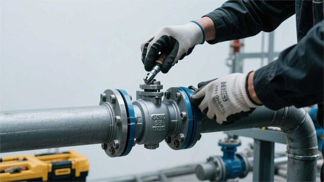
For maintenance work in chemical process piping, flanged ball valves follow the ASME B16.10 face-to-face standard.
Using a standard torque wrench, field technicians can remove 4 to 8 fastening bolts and replace the entire valve within 15 to 20 minutes.
Industrial reports from SMRP indicate that flanged connections eliminate the need for pipe cutting, beveling, field hot work welding, and radiographic inspection.
Downtime labor hours can be reduced by 65% for a single maintenance shutdown, and labor costs can drop by 40%.
Non-Destructive Removal
At a petrochemical plant in Texas, a 4-inch Schedule 40 carbon steel line carried 98% sulfuric acid. The line was rated at 150 PSI and operated at 120°C. Technicians received a work order to replace a seized valve in the middle section.
If the line had used a fully welded ball valve, the job would have immediately escalated to a Level 1 hot work operation. The safety supervisor would have issued a 14-page hot work permit. Two fully equipped workers would have climbed a 15-foot scaffold carrying an 80-pound grinder, gas cutting gear, and a welding machine.
A 10,000 RPM cutting wheel would slice into the pipe wall with sparks flying everywhere. Combustible gas alarms across the unit would have to be temporarily disabled. Removing the old valve would take 45 minutes, and the pipe length would be shortened by 2.5 inches.
Installing the new valve would then become a complex metal fitting job. The pipefitter would need a short pup piece of matching material to fill the gap. GTAW would create new weld seams, and root pass, fill, and cap welds would take nearly 3 hours.
The high-temperature arc would leave a heat-affected zone (HAZ) on the Duplex 2205 pipe wall. The grain structure would change, and the corrosion-resistant layer originally designed for a 15-year service life would be damaged along the weld edge.
After welding, the inspection team would arrive with radiographic equipment. Two weld films would cost $300. If even a 1 mm porosity defect were found, the entire weld would have to be ground out and redone.
The field picture is completely different with a flanged ball valve. Slip-on flanges complying with ASME B16.5 are pre-welded at both ends of the line. A spiral wound gasket with a centering ring is installed between the flange faces.
A maintenance worker climbs up with a 3/4-inch-drive pneumatic torque wrench. He sets the tool to 120 ft-lb and applies it to 8 high-strength ASTM A193 B7 alloy steel bolts.
He loosens the two bottom nuts first. A 2 mm gap opens between the flanges. A few ounces of sulfuric acid remaining at the bottom of the pipe drip through the gap into a polyethylene spill tray placed below. The worker stays safely behind a barrier throughout the procedure.
The pneumatic wrench rattles sharply, and the remaining 6 bolts are removed within 4 minutes. A hydraulic flange spreader then applies 5 tons of force and pushes the two flanges outward by 1.5 inches.
The 65-pound Class 300 carbon steel flanged ball valve loses clamping force and is lowered steadily to the ground on a lifting strap. The two connecting pipe sections remain completely stationary, and the spring hangers carrying 500 pounds do not shift at all.
The operator takes a new 4-inch 316L stainless steel graphite spiral wound gasket from the toolbox and inserts it between the flange faces. A same-size spare valve from the warehouse is lifted into place. The bolt holes align perfectly to standard dimensions.
The workers reinsert the 8 bolts. Tightening is done in a star pattern: first to 35 ft-lb, then to 85 ft-lb, and finally to the full 120 ft-lb. The entire tightening sequence takes 12 minutes.
| Maintenance Metric | Hot Work (Welded Connection) | Cold Work (Flanged Connection) |
|---|---|---|
| Hot work permit | Must be applied for 24 hours in advance | Not required |
| Trades involved | Welder, pipefitter, safety watch, NDT inspector | Mechanical maintenance technician (1-2 people) |
| Consumables | Argon, welding rod, cutting discs, pup piece | 8 bolts, 1 gasket |
| Inspection cost | Radiography / ultrasonic testing ($300+) | 50 PSI soap-bubble leak test ($0) |
| Pipe metallurgy | Creates HAZ | Retains original factory condition |
After repressurizing the line to operating pressure, workers spray leak-detection fluid around the flange edge. No bubbles appear. The line returns to service 45 minutes after shutdown.
Maintenance records from a chemical plant in the Port of Rotterdam show that pipe rack spacing is extremely tight, with only 6 inches between two parallel lines. Workers simply cannot get their elbows into the space to operate a large pipe cutter.
With flanged connections, all fasteners are exposed on the outside. A technician can reach every nut from the walkway using an extended socket wrench. The valve can be lifted straight up and removed vertically as a complete unit.
- Equipment eliminated from the jobsite:
- 220V inverter DC welding machine
- Industrial grinder and 14-inch cutting wheels
- Argon regulator and high-pressure gas cylinders
- Industrial radiography unit and radiation shielding lead container
During a major autumn turnaround (TAR), the plant needed to replace 120 aging valves within a 14-day shutdown window.
If welders had been assigned to all of those jobs, the schedule would have collapsed. Hiring one senior welder certified to ASME Section IX costs as much as $800 per day. Cutting and restoring 120 connection points would require 600 skilled labor hours.
Instead, the plant deployed three teams of ordinary mechanical assemblers. Working in pairs, they moved through the pipe racks with carts loaded with torque wrenches and spare bolts. One wrench removed the old valve, the new valve was inserted in place, and the nuts were tightened again.
All 120 flanged ball valves were replaced within 4 days. Contractor labor costs on the maintenance budget dropped by $85,000, and the plant restarted on schedule.
Three-Piece Design
At a polyurethane raw materials plant in Ludwigshafen, Germany, a 2-inch line carrying TDI at 150°C developed a minor leak. The control room showed line pressure gradually dropping from 300 PSI to 285 PSI. Maintenance records pointed to a flanged ball valve in the middle of the pipe rack.
The plant had installed three-piece flanged ball valves. The two end connections with ASME B16.5 flanges were locked firmly into the piping system. The center body, containing the ball and stem, was clamped in place by 4 ASTM A193 B8M long bolts.
Two technicians wearing Tyvek Level A protective suits climbed up with pneumatic tools. Using a 7/8-inch socket wrench, they removed the hex nuts from 3 of the long bolts. The bottom bolt remained untouched and acted as a physical hinge.
The technicians gently pushed the center section outward. Like opening a door, the center body swung out from the middle of the line and was fully exposed. The two flanged pipe ends, together weighing 600 pounds, did not shift by even a millimeter.
- Internal components visible after swing-out:
- 316L stainless steel polished ball
- Two modified PTFE seats with damaged edges
- Graphite packing rings coated with chemical residue
- External O-ring made of FKM
The fluid at both ends had already been isolated by upstream and downstream blinds. On the open pipe rack walkway, the technicians used needle-nose pliers to remove the worn PTFE seats. A visible 0.5 mm scratch had damaged the original smooth sealing surface.
A standard seal kit kept in stock at the plant was ready on hand. The technicians wiped chemical deposits from the stainless steel ball with a nonwoven cloth. Two brand-new white PTFE seats were pressed into the metal grooves in the center cavity. The three-layer V-type graphite packing at the top of the stem was replaced at the same time.
With a conventional one-piece valve, the technicians would have had to use a hoist to remove the entire 45-pound metal valve body from a 15-foot-high pipe rack and carry it half a mile back to the repair shop to place it in a vise. Disassembling rusted old threads is difficult and can easily damage the original machined threads.
- Maintenance steps avoided by the three-piece design:
- Dispatching and positioning large lifting equipment
- Physical protection of flange faces after full valve removal
- 40-minute round-trip transport to and from the workshop
- Risk of residual liquid splashing during transport of the center cavity
After replacing the internal parts, the technicians swung the center body back into the pipeline gap. The 3 long bolts were reinserted through the flange holes and fitted with industrial spring washers and high-strength nuts. The torque wrench was set to 65 ft-lb and tightened evenly in three diagonal passes.
A portable industrial nitrogen bottle was connected on site to inject 80 PSI test gas into the repaired line. The technicians sprayed Snoop leak detection fluid around the body joint seam. After 5 minutes, not a single bubble appeared.
This in-line elevated repair took 18 minutes. The bill of materials recorded only one PTFE seal kit costing $35. The TDI production line resumed feed and returned to full-load operation half an hour after shutdown.
- Actual downtime maintenance comparison (three-piece vs one-piece):
- On-site working time: 18 minutes vs 3.5 hours
- Labor required: 2 people vs 4 people
- Spare parts cost: $35 seal kit vs $450 full valve replacement
- System drain volume: 15 oz localized drain vs 120 gallons full-section drain
At a pharmaceutical raw material plant in Basel, Switzerland, high-purity active pharmaceutical ingredient (API) was being produced. A 3-inch sanitary three-piece flanged ball valve was installed on the discharge line below a reactor. The fluid temperature was 85°C, and line pressure was maintained at 1.2 MPa.
After each production batch, the line had to undergo a strict CIP process. In an ordinary valve design, about 15 mL of concentrated liquid from the previous batch could remain trapped in the internal cavity. Residual liquid in such dead legs could support bacterial growth and put the next antibiotic batch, worth €120,000, at risk of total loss.
Wearing nitrile gloves, the operator used a 15 mm adjustable wrench to loosen 3 corrosion-resistant M12 bolts. The center body hung on a bottom pivot and swung wide open.
With the interior exposed, industrial cleaning became straightforward. A high-pressure cleaning gun sprayed 80°C purified water (PW) onto the hidden metal dead space behind the 316L stainless steel ball. Visible white pharmaceutical powder residue was washed away by the strong water jet.
The cleaning operation took a total of 12 minutes. The operator then used a digital caliper to measure the edge thickness of the PTFE seat, which remained at the factory-standard 4.5 mm. The center body was closed and reset, and the next powder charging cycle started on time.
An Ohio fertilizer plant had more than 800 frequently operated shutoff points. Three years ago, the purchasing department replaced all of them with three-piece flanged ball valves. Maintenance records show that annual spending on replacing aged internal seals dropped by 72%. Maintenance personnel no longer had to perform labor-intensive full-pipe removal work.
Standardized Dimensions
A large refinery outside Houston had 50 miles of internal piping and more than 12,000 shutoff devices of various models registered in its SAP system. Three years ago, the purchasing manager conducted a complete inventory review of warehouse materials.
At the bottom of the No. 2 desulfurization tower, a 3-inch carbon steel ball valve developed internal leakage. The service medium was sulfur-bearing crude oil at 180°C, and the line was rated at 285 PSI. This valve was an older non-standard custom unit.
“When the night shift needed emergency repairs, we couldn’t find a spare in the same model. The warehouse only had another brand that was 0.5 inch shorter, and the pipefitter was on site stamping his feet with a tape measure in hand.” — Shift supervisor’s logbook
The plant spent 14 hours cutting pipe and re-welding weld-neck flanges just to force that mismatched spare into the system. A single unplanned shutdown caused $65,000 in lost production.
During the following turnaround, the engineering team converted 85% of the plant’s shutoff points to flanged ball valves compliant with ASME B16.10. This standard strictly fixes the face-to-face length of each valve.
A flanged ball valve rated NPS 2, Class 150 will always have a face-to-face dimension of exactly 7.00 inches, regardless of which country or manufacturer appears on the nameplate.
At an oil sands processing plant in Alberta, Canada, a high-pressure line alarm was triggered during a snowstorm at -30°C. A 6-inch Class 600 shutoff valve jammed in a half-open position while a high-viscosity bitumen slurry flowed through the line.
- Before retrieving a spare, field technicians only needed to confirm three basic parameters:
- Nominal pipe size: 6 inches (NPS 6)
- Pressure class: Class 600
- Facing type: RF (Raised Face)
A forklift pulled a brand-new spare from the temperature-controlled parts warehouse. The nameplate showed that the new valve and the failed valve in the line came from two completely different manufacturers.
The technicians removed the old valve, and the new one slid into place between the flanges on a lifting strap. Its 15.88-inch face-to-face length matched the pipe gap perfectly. Twelve 1-inch alloy bolts passed smoothly through the aligned bolt holes.
No pipe stretching was needed, and no hydraulic jack was used to force the flanges apart. The standardized physical dimensions turned cross-brand replacement into a simple block-assembly job.
The financial picture for materials management changed dramatically. In the past, the warehouse had to stock $1.2 million worth of non-standard custom spares organized by brand and model. Different manufacturers used different thread pitches and body lengths.
“After eliminating non-standard parts, we purchased 40 general-purpose flanged ball valves to ASME B16.5 as standing stock. Capital tied up in spare parts fell to $280,000.” — Purchasing department monthly report summary
The number of stocked spare types fell by 65%. As long as size and pressure class matched, workers could pull any unit from stock and install it on site. Warehouse staff no longer needed to check every incoming part with digital calipers.
An offshore oil platform in the North Sea faced strict space and weight limits. There was no spare room on deck to store pup pieces of different lengths to fit mismatched replacement parts.
- The platform’s standard spare parts inventory remained deliberately minimal:
- 8 units of 2-inch Class 300 stainless steel flanged ball valves (specified length 8.50 inches)
- 4 units of 4-inch Class 150 carbon steel flanged ball valves (specified length 9.00 inches)
- 200 pcs of perfectly matched 316L spiral wound gaskets
When offshore crews encountered a pipeline node heavily damaged by salt spray corrosion, they removed the old valve and inserted the new one. The 1/16-inch raised face on the flange engaged precisely with the gasket. Once the torque wrench reached 150 ft-lb, the flange gap fully met the airtight testing requirements of API 598.
At a fine chemicals plant in New Jersey, work order response time improved dramatically. The site had more than 300 one-inch lines carrying 99% methanol.
During a night inspection, one valve was found with external leakage exceeding 500 PPM. The duty pipefitter entered “NPS 1, Class 150, RF” into the ERP system. The system returned 12 available spares from three different purchasing batches.
The pipefitter rolled away the outermost spare on a small cart. Fifteen minutes later, a radio call came in from the field: the 5.00-inch flanged valve had fit back into the methanol line perfectly, and the portable VOC detector reading had dropped to zero.
The enforcement of industrial dimensional standards turned maintenance from a skill dependent on veteran pipefitters into a measurable, repeatable workflow. Highly standardized physical dimensions eliminated the need for complicated field measurement and delays caused by waiting for non-standard fabricated parts.
Secure Flange
Chemical process piping uses flanged ball valves connected through the metallic sealing faces and bolting system defined by ASME B16.5.
During installation, 4 to 24 alloy steel bolts, such as A193 B7, are tightened to specified torque values to compress a spiral wound metal gasket or PTFE gasket between the flange faces.
This connection structure can continuously withstand fluid pressures above 2,500 PSI and service temperatures from -196°C to 538°C.
When handling media such as 98% sulfuric acid or high-pressure chlorine gas, flanged connections provide far greater pullout resistance than threaded or clamped joints, keeping fugitive leakage below 100 ppm and maintaining a fully sealed pipeline system.
Bolts & Gaskets
On an ASME B16.5 Class 300 flange, 8 ASTM A193 B7 alloy steel bolts carry the fluid load. Installers use a hydraulic wrench to apply 450 N·m of torque in a cross-pattern sequence, forcing the metal gasket to yield physically.
The bolt material has a yield strength of up to 105 ksi (about 724 MPa). Under wrench load, each 5/8-inch bolt elongates by 0.15 to 0.25 mm, converting torque into lasting axial clamping force and drawing the flange faces tightly together.
The compressed 316L stainless steel spiral wound gasket is reduced in thickness from 4.5 mm to 3.2 mm. Inside the gasket, alternating layers of high-purity flexible graphite are driven into the machined grooves on the flange face.
API 6D specifies a flange face roughness of 125 to 250 microinches (Ra). At the microscopic level, the metal face is covered with concentric or spiral grooves, and the graphite fills these gaps to block any leak path for the process media.
| Bolt Material Standard | Nominal Yield Strength | Maximum Service Temperature | Matching Gasket Type | Specified Test Standard |
|---|---|---|---|---|
| ASTM A193 B7 | 105 ksi | 538°C | 316L spiral wound gasket | API 598 |
| ASTM A320 L7 | 105 ksi | -101°C | PCTFE fluoropolymer | ISO 15848-1 |
| ASTM A193 B8M | 30 ksi | 815°C | Graphite corrugated gasket | ASME B16.34 |
For liquid nitrogen service at -196°C, ASTM A320 L7 low-temperature carbon steel bolts are used instead. Ordinary steel becomes brittle in cryogenic conditions, while L7 can withstand 20 J in Charpy impact testing.
The matching seal is upgraded to high-density fluoropolymer. Because polymer contraction at ultra-low temperature is about twice that of metal, an additional 15% initial preload is required to compensate for differential shrinkage.
At a refinery in Texas, a hydrogen cracking unit operated at 450°C. High-temperature creep caused bolt tension to drop by 8% to 12% within 72 hours, putting flange integrity at risk.
Maintenance crews switched to Belleville spring washers installed beneath A194 2H heavy hex nuts. A single 3 mm-thick washer stores 7,000 N of mechanical energy when flattened and automatically compensates for small loosening caused by thermal expansion.
When pressure rises to ASME Class 1500, where working pressure can reach 3,700 PSI, raised face flanges are no longer used. Engineers switch to RTJ flanges with a trapezoidal ring groove cut 8 mm deep.
An R-type octagonal metal ring gasket is placed precisely into the groove. The gasket, made from low-carbon steel or Hastelloy C276, is kept below HB 120, making it 30 to 40 hardness units softer than the flange itself.
Bolt tightening generates local contact stress as high as 60,000 pounds, forcing the softer octagonal ring to flow plastically. The tapered sides of the ring engage with the 23-degree internal walls of the flange groove, forming a dead-tight metal-to-metal seal.
BASF’s chlorine production line uses B8M stainless steel bolts with a PTFE coating. The fluoropolymer coating is about 25 µm thick, improving corrosion resistance while reducing thread friction coefficient to 0.07.
The lower friction coefficient improves torque conversion efficiency by nearly 20%. With the same wrench reading, coated bolts deliver more accurate axial tension, keeping error within ±5% and preventing one-sided flange distortion.
- ASME PCC-1 Appendix O requires a four-step tightening procedure:
- Step 1: Apply 30% of target torque and confirm that flange gap variation around the circumference is no more than 0.8 mm.
- Step 2: Increase to 60% of target torque and monitor bolt elongation with an ultrasonic bolt measurement device.
- Step 3: Reach 100% full-load torque. A single 1-1/2 inch bolt will carry more than 50 tons of tension.
- Step 4: Perform two final clockwise passes at 100% torque to eliminate elastic interaction effects.
Elastic interaction in high-pressure flange systems causes adjacent bolts to affect each other during tightening. When the fourth bolt is tensioned, the third bolt next to it can instantly lose about 15% of its load.
On large NPS 24 flange joints, sequential tightening of 24 bolts can take hours. Crews therefore use hydraulic bolt tensioners mounted on 4 symmetrically placed bolts, using 70 MPa hydraulic cylinders to pull the bolt bodies directly.
Direct tensioning bypasses the energy losses caused by thread friction. While the bolt is held in tension, the nut is turned down by hand until it contacts the flange face. Once hydraulic pressure is released, the elastic recovery of the metal converts the bolt stretch into pure clamping load.
For lines carrying 98% sulfuric acid, a modified PTFE gasket filled with 20% barium sulfate is used. Pure PTFE tends to cold flow under long-term compression and can slowly creep outward from the flange at about 0.1 mm per month.
The inorganic filler reduces cold flow to below 2%. Even after 10,000 hours in a 150°C strong-acid environment, residual gasket thickness still remains above the acceptable minimum of 2.8 mm.
Highly toxic phosgene service requires tongue-and-groove flanges. One flange has a 6 mm-deep groove, and the mating flange has a 5.5 mm-high tongue, fully trapping a 3 mm-thick corrugated metal-jacketed gasket inside a sealed cavity.
Preload as high as 1,500 pounds compresses the metal jacket into the extremely narrow groove clearance. Even under sudden pressure pulses, the gasket has no physical path to blow out laterally, meeting the API 622 requirement for VOC fugitive emissions below 100 ppm.
Engineers use ultrasonic thickness measurement to perform non-destructive inspection on ASTM A193 B8M stainless steel bolts after five years of service. On vinyl chloride monomer lines exposed to frequent thermal cycling from -40°C to 200°C, the test waveform can reveal fatigue cracks smaller than 0.02 mm at the thread roots.
Pipe Load Distribution & Vibration Resistance
A 500-horsepower centrifugal pump at Dow in Houston injects liquid chlorine into the pipeline at 3,600 RPM. This creates continuous 60 Hz mechanical vibration, and the destructive high-frequency energy travels through the steel pipe for tens of meters.
Threaded pipe fittings subjected to continuous 60 Hz vibration for 72 hours can develop fatigue cracks as deep as 0.4 mm at the engaged threads. A flanged joint acts as a massive physical anchor block.
A standard forged steel NPS 10 Class 300 flange weighs 68 kg. Welded to the end of the line, its sheer mass interrupts the transmission path of the high-frequency mechanical wave.
Sixteen 1-1/8 inch bolt holes are evenly distributed around the flange. When vertical pipe motion generates 15,000 N of shear force, the heavy flange breaks that one-direction load apart.
The load is distributed across 16 high-strength alloy bolts. The lateral shear force on each bolt drops to less than 1,000 N, far below the material yield limit of 105,000 PSI.
- Handles compressor motor resonance up to 120 Hz
- Absorbs 4,000 lb of instantaneous impact from liquid surge
- Resists industrial seismic simulation at 0.5g acceleration
- Withstands outdoor pipe-rack wind gusts of 140 km/h
In the Port of Rotterdam, an outdoor chemical line carries 280°C superheated steam. A straight 50-meter carbon steel run expands linearly by 18 mm when heated from ambient temperature to operating temperature.
The lengthened steel pipe imposes up to 45,000 ft-lb of torsional bending moment on the ball valve at the end. The line is effectively trying to pull the valve out of position with tremendous force.
The wide metallic flange face provides a large physical contact area. With an outside diameter of 17.5 inches, the mating flanges spread concentrated point stress across several hundred square centimeters of metal surface.
Downstream, an operator suddenly shuts a pneumatic isolation valve in 0.5 seconds. A liquid hydrocarbon stream moving at 8 m/s stops instantly, and its kinetic energy becomes a destructive water hammer.
A pressure wave travels back through the line at 1,400 m/s. In only fractions of a second, pressure inside the line rises from 150 PSI to 800 PSI.
- Hydrostatic shell test at 1.5 times working pressure (1,125 PSI)
- API 591 thermal shock testing over 50 cycles from 20°C to 200°C
- Bending fatigue test exceeding 2 million cycles at 100 Hz
Raised-face flanges manufactured to ASME B16.5 have a raised land thickness of at least 0.06 inch. When fluid expansion tries to force the pipe joint apart, the 16 bolts stretch by 0.12 mm in milliseconds.
This tiny elastic elongation absorbs the energy carried by the water hammer. Once the shock wave dissipates, the elastic recovery of the metal immediately pulls the nuts back into place, and the flange faces clamp tightly together again.
Offshore drilling platforms in the North Sea face even harsher mechanical loads. Waves as high as 15 meters strike the support legs, causing the chemical piping system to sway irregularly by 3 to 5 degrees every day.
With clamped connections, just a few weeks of movement is enough to create 2 mm of lateral slip at the joint. Heavy flanges use preload as high as 60,000 pounds to generate massive static friction and lock out sideways movement.
The stainless steel spiral wound gasket clamped between the two metal discs has a V-shaped cross-section. Under hundreds of tiny vibrations per minute, the V-profile itself acts like a microscopic damping spring.
As the flange load fluctuates, the gasket repeatedly compresses and rebounds over a travel of 0.08 mm. It fills the temporary gaps created by vibration and leaves no opening for chemical media to escape.
- Raised Face (RF) flanges concentrate clamping force over a smaller area
- Ring Type Joint (RTJ) flanges are used for pressures above 6,000 PSI
- Flat Face (FF) flanges prevent cracking in cast iron piping
- Tongue-and-groove designs completely prevent lateral gasket blowout
Before tightening bolts, pipefitters use a laser alignment device to check flange parallelism. Gap variation between the two unloaded flanges is strictly limited to within 0.25 mm.
If bolts are used to forcibly pull together two misaligned pipes with a 2-degree angular offset, the pipe wall will immediately accumulate 20,000 PSI of initial residual stress. The system has not even started operating, yet the material is already close to severe fatigue.
Heavy flanged ball valves are usually placed on structural steel pipe supports. A valve body weighing 120 kg together with both flanges bears vertically on PTFE slide plates below.
As the system heats up during startup, the heavy flange assembly can slide as much as 50 mm across the slide plates. The flange system preserves overall pipeline rigidity and transfers thermal movement to the sliding support below.
Maintenance engineers inspect Class 1500 high-pressure lines using ultrasonic bolt measurement tools. The probe is placed on top of the bolt and sends a 5 MHz high-frequency sound wave through the entire metal rod.
The instrument measures fatigue-related bolt elongation under long-term high-frequency vibration with a precision of 0.001 inch. If any bolt exceeds the safety tolerance by 0.05 mm, the crew immediately isolates the line and replaces it.
Pressure & Pullout Resistance
At a natural gas processing plant in Alberta, Canada, a Schedule 80 thick-wall carbon steel line carries untreated sour gas. Initial operating pressure remains at 2,250 PSI. The gas contains small liquid droplets that strike the pipe wall and valve connection at 15 m/s.
Ordinary threaded fittings cannot survive this pressure for more than a week. The thread flanks are subjected to continuous lateral load at 2,000 PSI, and the 0.5 mm-deep threads are gradually eroded flat by the high-pressure gas stream until the fitting begins to slip out.
Engineers replace them with ASME Class 900 weld-neck (WN) flanges. The tapered hub of the weld-neck flange is 85 mm long, transferring the tens of thousands of pounds of lateral pull force inside the pipe to the thicker metal section at the flange root.
Under API 6D hydrostatic shell testing, a Class 900 flange assembly must be filled with water to 3,350 PSI and held for at least 15 minutes, while deformation at the outer flange edge must remain below 0.02 mm.
The flow area at both ends of the line is 314 cm². With 2,250 PSI acting on that area, the joint is subjected to a tremendous separating force of up to 31,000 pounds trying to pull the two pipe sections apart.
Sixteen 1.5-inch alloy bolts lock firmly against the outer shoulder of the flange. The solid forged flange rim is 63.5 mm thick, equivalent to a small armor plate, physically preventing the nuts from slipping outward.
- Class 1500 flange outside diameter reaches 26.5 inches
- Can withstand an instantaneous 10,000 PSI pressure burst
- 1:3 tapered hub transfers bending stress caused by pressure loading
An ethylene cracking unit on the Gulf Coast experiences an emergency shutdown. A pneumatic valve cuts off a liquid hydrocarbon stream flowing at 12 m/s in just 0.3 seconds, triggering a highly destructive water hammer event.
Within 3 milliseconds, local pressure surges to 3.5 times normal operating pressure, exceeding 4,500 PSI. The huge kinetic energy of the liquid slams into the closed ball valve like a battering ram, generating a violent longitudinal pullout force along the flow direction.
The flanges on both sides of the valve become the only structural points resisting that force. The metal shoulders on the back of the flanges absorb an instantaneous impact of more than 80 tons. The bolts stretch by 0.18 mm and physically restrain the valve body from tearing away from its support.
ASME B31.3 prohibits the use of socket-weld fittings or clamped joints in lines subject to severe water hammer. The extra metal mass of a flange provides absolute structural redundancy against the fitting being ripped out of the connection.
In severe combined high-pressure and high-temperature service, flange pullout protection becomes even more robust. In Jubail Industrial City, Saudi Arabia, a hot heat-transfer oil line runs continuously at 420°C and 1,200 PSI.
Engineers abandon standard RF flanges and switch to RTJ flanges with a deep groove. The flange face is machined with a 12 mm-deep trapezoidal groove, and the groove side angle is precisely controlled at 23 degrees.
- R-type metal ring gasket hardness is 30 HB lower than the flange material
- Ring groove wall finish is polished to 63 microinches
- In the locked condition, it can resist 50 tons of lateral pullout force
An octagonal metal ring is placed inside the flange groove. A hydraulic wrench applies an extreme torque of 3,000 N·m, forcing the tapered sides of the ring gasket into the trapezoidal groove walls and creating a fully locked metal-to-metal seal.
When internal heat-transfer oil pressure surges and tries to spread the flanges apart by 0.5 mm, the ring gasket remains jammed in the 23-degree groove. The higher the internal pressure, the greater the outward force that drives the ring harder against the groove wall.
High-pressure gas systems are often exposed to severe Joule-Thomson cooling during decompression. At a natural gas booster station outside Houston, a minor leak develops at one connection point, and 2,500 PSI gas immediately undergoes throttling expansion at the leak site.
As the gas expands outward, it removes a large amount of heat. Local metal temperature on the flange drops from 35°C to -45°C within 120 seconds. The carbon steel flange contracts under freezing conditions, and bolt preload falls by 15%.
In this extreme leak-and-freeze environment, the Belleville washers installed on the flange bolts instantly release the 7,500 pounds of spring energy they have stored for three years, forcing the loosened 3 mm gap back into place.
Standard flange forgings are made from a single ASTM A105 carbon steel billet, forged under heavy hammering at 1,200°C. The metal grain structure follows the contour of the flange, eliminating internal porosity and blowholes common in cast components.
When tearing stress above 3,000 PSI develops inside the line, the solid forged structure leaves the fluid no structural weak point to exploit. The flat machined area on the back of the flange ensures 100% contact with the heavy nuts, eliminating the possibility of tilted or eccentric loading.
A chemical plant in Louisiana replaced all of its highly toxic phosgene lines with heavy Class 600 flanges. In actual service, the phosgene line operated at only 150 PSI, far below the 1,480 PSI pressure capacity of a Class 600 flange.
Spending three times the engineering budget on heavy-duty flanges bought an extra 38 mm of solid metal wall thickness. When the entire pipe was bent to a 30-degree angle by the collapse of an external heavy crane, the thick metal at the flange joint did not move at all, and the pipeline was not pulled apart.

")