
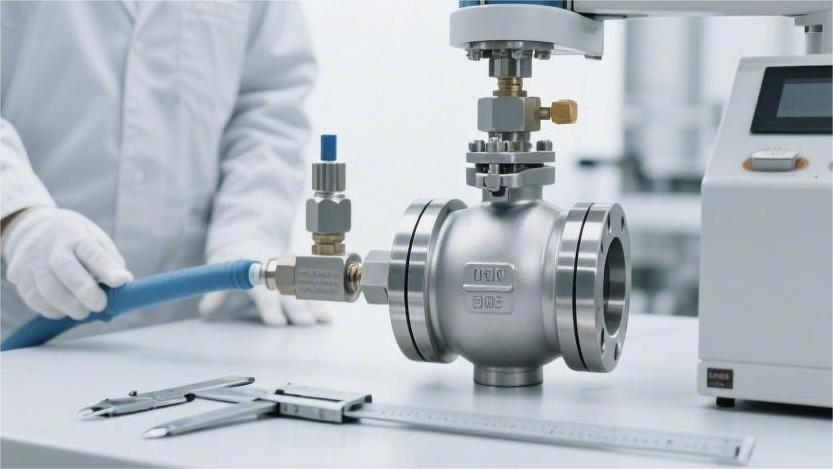
When evaluating ball valve manufacturers, buyers first match the supplier’s offering to the project requirements, such as Class 300–1500 pressure ratings and service temperatures from -29°C to 425°C.
They then assess sample performance against criteria including leakage within API 598 limits and opening/closing torque deviation within ±10%, while also confirming API 6D certification, ISO 9001 certification, and complete material traceability reports.
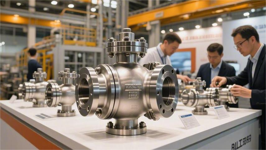
In most cases, buyers compare 3–5 suppliers before selecting a qualified manufacturer.
Project Fit
Materials & Service Conditions
Buyers start by reviewing the factory’s procurement records from the previous year, checking mill delivery notes line by line. What they are looking for is 2507 super duplex stainless steel.
Its corrosion resistance rating, expressed as PREN, must exceed 40. Even a shortfall of 0.1 is enough for the entire heat of molten steel to be rejected and sent back to the mill.
An inspector presses a handheld spectrometer firmly against a cut metal sample for 30 seconds. The display immediately shows the percentages of chromium, molybdenum, and nitrogen.
A 24-inch valve body is then scanned with an ultrasonic flaw detector. If the image reveals even a 2 mm crack, the entire casting is rejected.
- Ferrite content must stay strictly between 35% and 55%
- Annealing temperature must be held at exactly 1040°C
- At -46°C, impact energy must still reach 45 J
- Weight loss in ferric chloride solution must not exceed 4 g
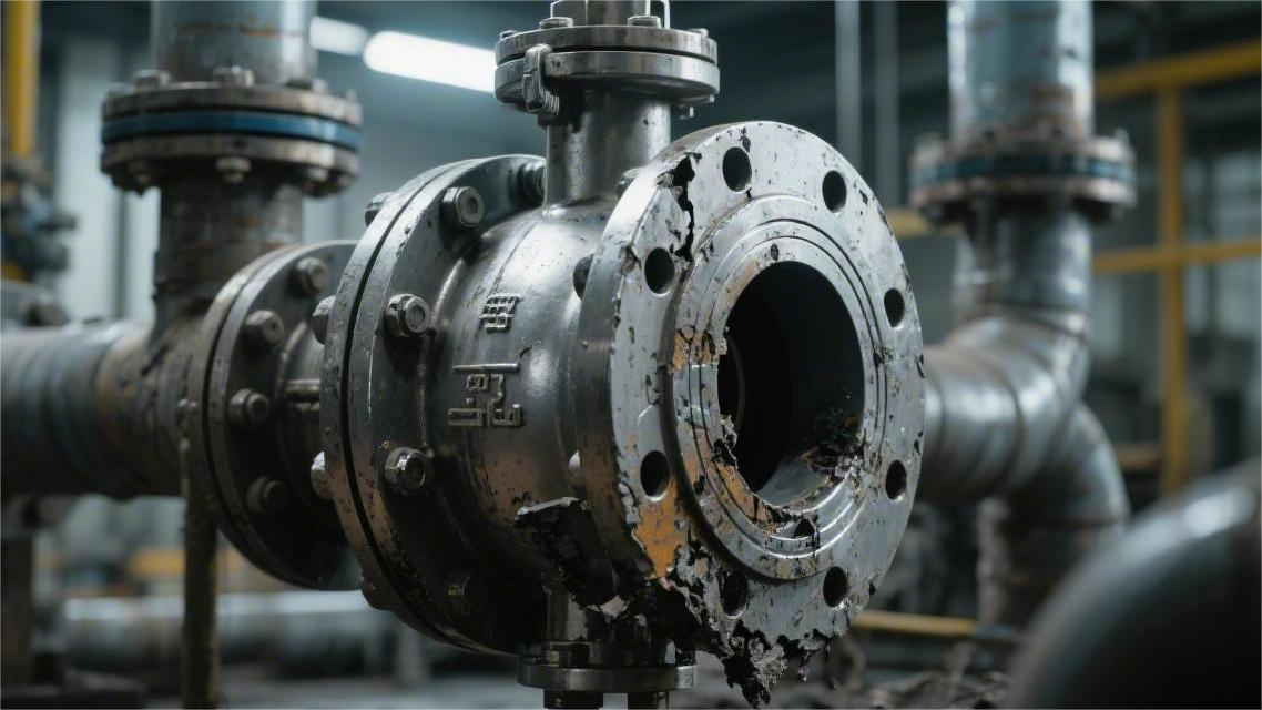
At sour gas sites, field pipelines can contain hydrogen sulfide concentrations as high as 150,000 ppm. Ordinary steel can blister and crack apart within hours under those conditions.
For this type of service, the specified material is often upgraded to costly C276 alloy. Where budgets are tighter, a layer of Inconel 625 is overlaid onto standard steel.
The valve cavity is coated evenly with an acid-resistant protective layer at least 3 mm thick. A welder qualified to ASME Section IX works in full protective gear.
Using GTAW, the welder slowly deposits the weld on the inner wall of the shell, which has been preheated to 150°C.
A supervisor then checks the finished surface point by point with a calibrated gauge. The drawing requires a probe reading every 10 mm.
If the instrument shows iron contamination above 5%, the entire area is ground out and welded again.
- Surface hardness must not exceed 22 HRC
- The surface is checked under a microscope for fine cracks
- Cooling curves are monitored after welding in a heat-retention enclosure
- Dye penetrant is used to check whether edge areas show bleed-out
In coal preparation plants, the pipeline carries thick black slurry containing 30% hard coal ash, with operating temperatures reaching 450°C.
A white PTFE seat exposed to that hot slurry can soften within seconds. In those workshops, all soft components are replaced with cast iron and hardened steel.
Next to the machining table, a robotic arm turns and directs its spray gun at a polished steel ball. Fine tungsten carbide powder is driven forward by combustion gases.
The powder strikes the steel surface at roughly Mach 2.5, forming an ultra-hard “armor” layer 0.3 mm thick.
The coated parts are then moved into a furnace at 980°C and fired repeatedly until the coating becomes a fully bonded hard shell.
After firing, two skilled technicians spend four full hours hand-lapping the ball and seat with 400-mesh diamond compound.
The assembled unit is bolted together and connected to a thick hose charged with high-pressure nitrogen. An infrared camera watches continuously for leaks.
If leakage stays below 0.0005 mL over one minute, the unit passes, and a V-grade leak-tightness label is printed immediately.
- Surface hardness exceeds 68 HRC
- Bond strength is greater than 70 MPa
- Ball surface finish is polished to 0.1 μm
- Sphericity tolerance is kept within 0.02 mm
LNG tanks operate continuously at -196°C. Buyers therefore review how the 316L stainless components were treated for cryogenic service.
Hundreds of metal pieces are loaded into stainless steel mesh baskets and immersed in liquid nitrogen for a full 24 hours.
This extreme thermal cycling forces the internal structure into a more stable state, keeping shrinkage deformation below 0.15% once installed in cryogenic piping.
Soft graphite packing is not permitted at the stem position. Instead, assemblers install a special PCTFE ring with a custom hex tool.
Inside that ring is a U-shaped corrosion-resistant metal spring. No matter how low the outside temperature falls, the spring keeps constant pressure on the plastic ring to prevent leakage.
A helium leak detector is then brought in. The inspector moves the suction probe slowly around the stem seal area.
The scanning speed is kept at 10 mm per second. On the display, the leakage reading remains safely below the 100 ppm limit.
Capacity & Lead Time
For a 400 km gas transmission line, the requirement may be clear: 8,000 ball valves of various sizes must be delivered within six months.
Buyers do not rely on sales claims alone. They count the machines themselves. On one side of the workshop are 45 CNC lathes with digital displays; on the other are 12 horizontal machining centers.
They watch the cycle timers on the screens and use stopwatches to verify machining time per unit. For a standard 8-inch carbon steel body, the cutting tool may need 35 passes across the workpiece.
Just keeping the spindle running for that job can consume 45 minutes. Some factories claim “10,000 units per month” in glossy brochures, but buyers want proof from the shop floor.
Experienced buyers will go as far as checking three months of employee attendance records and comparing them against electricity bills from the utility provider.
- Two shifts rotate between day and night work
- Machines run 16 hours per day at full capacity
- Workers operate 6 days per week
- The plant stops for 3 maintenance days every month
With those figures, a buyer can quickly calculate the factory’s true monthly output ceiling.
Large-diameter valves slow everything down dramatically. At one crude oil terminal project, the urgent requirement was for several 48-inch pipeline ball valves.
Each finished valve weighed around 15 tons. Ordinary lathes could not handle parts of that size, so the factory had to rely on its only two heavy vertical turning lathes.
Even at full operation, those machines could remove only about 3 tons of steel chips per day. Machining a single giant solid ball to final roundness took 72 continuous hours.
After machining, dimensions still had to stay within 0.5 mm. If the contract required 20 of those 48-inch units, production scheduling became a serious constraint.
Twenty valves at three days each means 60 days of machining time alone, assuming both machines run without belt failures or motor burnout.
Impatient buyers often drive 50 km to inspect the foundry as well. The yard is filled with wooden patterns, while resin-bonded sand molds sit hardened on the ground.
A 5-ton pour of molten steel is made into the mold boxes, and no one dares quench them with water. To prevent internal cracking, the casting must remain buried in sand for 15 days.
Once the castings finally reach the assembly shop, the hydrotest station becomes the next bottleneck. There may be 500 finished valves waiting in the yard, yet the factory has only four high-pressure test stands.
Under API 6D, each valve must be filled with water, brought to pressure, and then watched for a full 15 minutes by four operators.
Even at full pace, one day shift can test at most 60 units. With hundreds waiting in queue, the aisles can stay blocked for more than a week.
To avoid delaying trenching crews on site, buyers often prepare a phased shipment plan and force the supplier to stagger deliveries.
| Shipment Batch | Valve Sizes and Quantities | Machining + Assembly Time | Pressure Testing + Crating Time |
|---|---|---|---|
| First batch | 2″ to 4″, 3,000 units | Weeks 1–3 | Shipped in Week 4 |
| Second batch | 6″ to 12″, 2,500 units | Weeks 3–6 | Shipped in Week 7 |
| Third batch | 14″ to 24″, 1,500 units | Weeks 5–9 | Shipped in Week 10 |
| Final batch | 1,000 units in special alloy configurations | Weeks 8–14 | Shipped in Week 15 |
The first urgent batch of 2-inch valves left the plant on the morning of Day 30. Workers loaded them into heavy wooden crates with fumigation stamps and packed the gaps with large desiccant bags.
If the site routing suddenly changes and 15 non-standard flanged ball valves are needed immediately, experienced buyers do not assign that work to a massive factory.
Large plants may not even start processing the order until the following month. Instead, buyers go to a mid-sized factory with around 150 workers and pay for a special fast-track line.
- Three machines are reserved specifically for the rush order
- Two senior craftsmen are assigned exclusively to assembly
- One hydrotest pump is kept available without queueing
- White PTFE seats are cut and installed on demand
Under that setup, raw 316L forgings delivered on Monday morning can become packed and labeled valves by Friday afternoon. The entire process takes only five days.
Painting is another hidden delay. Cheap alkyd paint can dry in two hours.
Marine-service valves, however, usually require three thick coats of epoxy primer. Each coat must be baked for 8 hours at 60°C, and the curing process cannot be rushed.
That means 24 hours disappear just in painting alone. If the inspector finds even one blister larger than 1 mm, the coating has to be stripped and reapplied, delaying pickup by another day.
The overhead crane also limits throughput. Lifting one large valve, moving it into the paint room, and repositioning it can consume 20 minutes each cycle.
Experienced buyers will even measure the distance from the lathe area to the clean assembly room. If a forklift must carry finished parts 150 meters across a rough concrete yard, it wastes time and risks denting polished surfaces.
The most efficient plant layout is always a straight-through flow: rusty blanks come in from the east rolling door, move through machining and polishing, pass along the roller line for assembly, and then exit directly through the west gate onto a 17-meter flatbed truck.
Sample Quality
Unpacking the Sample
A utility knife cuts through a 7 mm five-layer double-wall corrugated carton. Once the product is removed, the industrial scale settles at 14.5 kg. This DN50 stainless steel ball valve is wrapped in EPE foam and surrounded by 20 mm-thick shock-absorbing pads.
The VCI anti-corrosion bag has a white production batch number printed on the surface. A micrometer measures the polyethylene film at 0.12 mm thick. Two 30 g indicating silica gel packs lie at opposite corners inside the bag, their granules a bright light blue and audibly crisp when pressed through the film.
Once the heat-sealed edge of the bag is cut open, there is a faint smell of rust-preventive oil. At both flanged ends are 5 mm-thick yellow PVC protectors with clean edges and no cutting burrs. Four plastic ribs lock tightly into the flange bore.
When the cap is pulled off, compressed air releases with a short pop. Under the overhead light, the raised flange face shows concentric machining marks reflecting a fine metallic sheen. Running a fingernail across the surface gives a regular, controlled drag.
A surface roughness comparison block is placed against the flange face, and the texture matches the 125–250 AARH range. The four 19 mm bolt holes on the rear side are smooth, with no sign of even a 0.5 mm drill chip.
- Measured flange thickness: 16.3 mm
- Measured flange outer diameter: 165 mm
- Diagonal center distance across the four bolt holes: 125 mm
- Estimated machining groove depth: about 0.05 mm
Moving up to the valve body, the surface shows the smooth finish typical of silica-sol investment casting, free of the grainy feel associated with poor castings. The surface has been evenly shot-blasted with 0.8 mm stainless steel shot, giving it a texture similar to 400-grit wet sandpaper.
A faint trace of yellow passivation compound remains near the base of the flange. Once wiped with alcohol, the true silver finish of the metal appears. The pickling and passivation process has been done thoroughly, with no dark oxidation stains or yellow specks anywhere on the body.
The cast markings for heat number, material, and nominal size are molded into the side of the body. The raised characters stand 2 mm high, and every stroke in the marking CF8M is full and well formed. The spacing between the groups of letters and numbers is an even 3 mm.
The nameplate is fixed to the flange neck with four 304 stainless steel blind rivets. On the 80 × 40 mm plate, the black laser-etched characters are cut 0.2 mm deep and can be felt clearly by touch.
The carbon steel handle is fitted with a 2 mm-thick blue PVC anti-slip sleeve. The tail end is cleanly cut, with no sharp injection-molding flash. A 2 mm-wide red anti-loosening paint mark is applied to the side of the M10 compression nut.
- Handle travel is limited to 90° by the stop block
- The grip sleeve covers two-thirds of the handle length
- Compression nut thickness: 8 mm
- Anti-blowout shoulder at the top of the stem: 3 mm wide
The four M16 hex bolts joining the two halves of the body are arranged diagonally. When a torque wrench is set to 85 N·m and applied again, it clicks immediately, showing that the factory originally assembled the fasteners with calibrated pneumatic torque equipment. The bolt heads are clearly forged with the 10.9 strength grade mark.
Material Verification
As the double acoustic doors close, the noise of heavy cutting equipment outside disappears. On a wooden inspection table lies a 3 mm-thick black antistatic rubber mat. Wearing clean white gloves, the inspector lifts the 14.5 kg valve onto the table.
A grinder fitted with a new 120-grit aluminum oxide flap disc is used on a blank area of the non-machined cast surface beside the flange. At 11,000 rpm, it throws a faint stream of orange sparks about 20 cm long.
After 5 seconds of grinding, the surface oil and oxidation film are removed, exposing a bright silver metal area roughly 15 × 15 mm. The spot is then wiped clean with a microfiber cloth soaked in 99% industrial alcohol.
A 1.5 kg handheld XRF analyzer is removed from a black explosion-proof instrument case. The nose of the gun is pressed tightly against the prepared test spot, and the inspector pulls the trigger. A red warning light begins flashing rapidly.
The countdown on the upper right corner of the display starts at 15. A miniature X-ray tube emits 50 kV into the stainless steel, while the detector captures the characteristic energy signatures of each element.
With a short electronic beep, the 5-inch touch screen displays a dense list of element symbols and percentages. On the first line, the alloy match library shows 316 in green, with a match score of 99.8%.
Molybdenum is critical to the corrosion resistance of the valve. The display shows Mo at 2.15%. According to the built-in ASTM A351 database, the acceptable range is 2.0% to 3.0%, so the reading passes comfortably.
The inspector then checks chromium and nickel. Cr reads 18.42%, and Ni reads 9.65%, both within the acceptable composition range. These values are copied by hand onto the upper corner of the inspection report.
Because handheld XRF cannot accurately measure very low carbon content, the sample is moved to a benchtop optical emission spectrometer. Next to it stands a cylinder of 99.999% argon with the pressure gauge reading 15 MPa.
The electrode sparks three times on a second prepared test area, each spark lasting 8 seconds. After a brief calculation, the display gives the final carbon result: 0.045%.
| Element | ASTM A351 CF8M Requirement (%) | Laboratory Result (%) | Verdict |
|---|---|---|---|
| Carbon (C) | ≤ 0.08 | 0.045 | Pass |
| Chromium (Cr) | 18.00–21.00 | 18.42 | Pass |
| Nickel (Ni) | 9.00–12.00 | 9.65 | Pass |
| Molybdenum (Mo) | 2.00–3.00 | 2.15 | Pass |
A two-page EN 10204 3.1 material certificate is clipped to the inspection board. It was issued by the upstream foundry that supplied the casting blank. The heat number printed on the certificate, 1A2B3C, matches the cast marking on the valve body exactly.
The molybdenum content on the paper certificate is 2.18%, compared with the benchtop spectrometer’s 2.15%. The 0.03% difference is accepted as normal variation between instruments, and the inspector stamps the report as passed.
A digital ultrasonic thickness gauge is then taken from the drawer. A transparent blue couplant is applied to the probe, and the sound velocity is set to 5800 m/s for austenitic stainless steel. The probe is pressed against the curved midsection of the body.
The display reads 9.8 mm. Since a caliper cannot reach the dark internal areas of the cavity, the small probe fills that measurement gap.
According to ASME B16.34, the minimum wall thickness for a Class 300 DN50 valve is 8.7 mm. The actual reading of 9.8 mm provides a 1.1 mm safety margin against long-term erosion.
The probe is then moved slowly around the body, with readings taken at eight positions. The highest reading is 10.1 mm, and the lowest is 9.5 mm, showing very uniform wall thickness and no obvious casting eccentricity.
The valve is carefully flipped over on the rubber mat. A portable Leeb hardness tester is placed against a smooth area on the rear side of the flange. With a sharp click, the tungsten carbide impact body strikes the surface, and the display reads 165 HB.
Three adjacent test points are marked, and the average of the three readings is 168 HB. Since the stainless steel casting underwent solution treatment at 1050°C before shipment, the hardness remains safely below the 200 HB maximum limit.
Finally, a transparent rust-preventive touch-up coating is sprayed onto the ground test spot. The blue ultrasonic couplant is cleaned off with cotton swabs, and the valve is sealed back into the VCI bag.
Pressure Resistance Testing
The three hardened jaws of a hydraulic clamp open slowly and secure the DN50 stainless steel ball valve firmly onto the cast iron test platform.
An operator uses a pneumatic hex wrench to tighten the blind flange bolts on the lower side of the test stand to 120 N·m.
A 3 mm PTFE gasket is placed between the blind flange and the valve flange. The handle is set to a half-open 45° position.
Keeping the valve half open allows the cavity to fill completely with liquid and vent all trapped air, preventing dangerous water hammer during pressurization.
The pump motor starts with a low rumble. Industrial tap water, filtered through three 80-mesh stainless screens, is pumped into the valve cavity at 20 L/min.
A temperature gun shows the water line at 15°C. The vent valve releases foamy water at first.
Once the flow turns clear, the operator closes the vent. The control knob on the console is turned three full turns clockwise.
The digital pressure gauge begins rising rapidly from 0.1 MPa. The instrument has an industrial accuracy of 0.01 MPa.
- After 10 seconds, the pressure reaches 3.0 MPa
- After 15 seconds, it reaches 5.1 MPa
- After 22 seconds, it stabilizes at 7.6 MPa
A pressure of 7.6 MPa corresponds to the 1.5× standard hydrostatic shell test pressure for a Class 300 valve. The pump stops, and a 60-second hold period begins.
With a 600-lumen flashlight, the operator inspects the outer body surface inch by inch.
Special attention is paid to the bolted joint between the two body halves. Even a single 1 mm droplet would show clearly under the beam.
Under API 598, the shell test must show no visible dripping or surface sweating during the required pressure hold period.
At the end of 60 seconds, the gauge still reads 7.6 MPa. The pressure is released, and the water drains into the collection line.
The handle is then moved fully closed to 0°. Water is reintroduced from the left side, and the pressure is brought to 5.5 MPa.
That 1.1× pressure is applied to one side of the ball. On the opposite side, the blind flange is removed with a 350 mm adjustable wrench.
A dry degreased cotton swab is inserted into the outlet cavity and rubbed three times along the interface between the PTFE seat and the metal ball.
When the swab is removed, it remains completely white and dry. The soft PTFE seat has sealed successfully by elastic deformation.
The 5.5 MPa pressure is held for a full two minutes. Not a single drop appears at the opposite end, and the high-pressure seat test is marked as passed.
The water is then drained completely. A 3 kW air compressor is switched on, changing the test medium from water to compressed air.
- Air pressure is regulated precisely to 0.6 MPa
- The blind flange is reinstalled on the right-side flange end
- The flange bolts are retightened to 100 N·m
Compressed air is fed continuously into the valve cavity from the left side. A transparent silicone tube with an 8 mm inner diameter is connected to the center of the right-side blind flange.
The other end of the tube is submerged in a large glass cylinder filled with purified water. The water surface remains perfectly still.
Gas molecules are much smaller than water molecules, so a 0.6 MPa air test can reveal tiny leakage paths that a hydrostatic test may not show.
The inspector watches the submerged tube for 60 seconds with a stopwatch. No bubbles appear.
This confirms compliance with ISO 5208 Class A zero leakage for the air tightness test. The air supply is shut off, and the hiss of venting gas echoes through the workshop.
Water is then introduced again, and the line is brought to the rated working pressure of 5.1 MPa. An electronic torque wrench is fitted to the handle base.
The operator applies force slowly until the ball begins to turn against the side load created by the water pressure.
The torque reading peaks at 42 N·m, and the pressurized operating torque is recorded in the final line of the test report.
Certification Readiness
Routine Quality Review
The workshop machines 3 tons of WCB carbon steel blanks every day, while the defect rate is kept below 0.05%. This week, 4,200 DN50 balls were produced, and only 3 were scrapped because the outside diameter exceeded tolerance by 0.02 mm.
On the night shift, abnormal tool wear was detected. A corrective action form was completed, spindle speed was reduced from 1500 rpm to 1250 rpm, and feed was reduced by 0.05 mm. After rechecking with a Zeiss probe, dimensional error returned to within 0.005 mm, and production resumed under the new parameters.
The QC room is maintained year-round at 20°C and 45% relative humidity. Calibration records are detailed and complete:
- Calipers are calibrated one by one using Grade 0 gauge blocks
- The diamond stylus on the roughness tester is sent out for calibration every 6 months
- Wear tolerance on thread plug gauges is controlled within 0.015 mm
- Spectrometer argon purity is specified at 99.999%
A traveler card must be signed by 12 people before the part can move through the process. PTFE seats are not released for assembly unless hardness falls between 55 and 65. Workers set the torque wrench to 120 N·m and tighten six M16 studs in a crisscross sequence.
The pressure test area works strictly to API 598. A DN100 valve is charged with 2.2 MPa air and held underwater for 120 seconds to check for bubbles. Nearby, a cast steel valve is undergoing hydrotesting at 15.0 MPa.
Before packing, inspectors check each item with a flashlight:
- Flange serration roughness is controlled within 3.2 to 6.3 μm
- Stem anti-blowout clearance measures under 0.1 mm with a feeler gauge
- Handle operating torque stays below 65 N·m
- Antistatic spring resistance is below 10 Ω
- Marking depth on the stainless steel nameplate is 0.2 to 0.3 mm
When batch code A24G08 is entered, the computer retrieves the 12-digit barcode from the supply document issued three months earlier. The chemistry report clearly lists carbon at 0.23% and sulfur at 0.012%.
Last week, incorrect spring washers were assembled by mistake. The entire plant spent 14 hours checking work-in-progress. The warehouse froze 850 parts from the same batch, and 42 pieces that had already entered final assembly were fully disassembled and verified within one hour.
One long-term rubber supplier was downgraded to Category C after failing to reach a 98.5% dimensional acceptance rate for three consecutive months. The purchasing manager visited the supplier and brought back an 8D corrective action report focused on uneven rubber compounding.
Supplier retention depends on hard metrics:
- Monthly on-time inbound delivery rate must reach 95%
- Temporary countermeasures must be provided within 24 hours of a defect notice
- Six consecutive lots must pass inspection at 100%
- Fewer than 50 defective pieces are allowed in every 10,000 sampled
A skills matrix is posted on the whiteboard. Of 32 machining operators, only 8 have earned Level 3 qualification and are authorized to machine F51 duplex stainless steel.
The QC department is scheduled for blind testing next Tuesday. Two newer operators in yellow hard hats are still practicing with ultrasonic thickness gauges on six-step reference blocks.
Mandatory Industrial Certifications
The auditor opens a quality manual more than 600 pages long for API 6D. The very first item on the checklist is whether the factory is authorized to stamp the official monogram on metal valve bodies.
The QSL-2 product list includes an H₂S-resistant valve stem compliant with NACE MR0175. Three hardness measurements taken with an ultrasonic tester read HRC 20.5, 21.2, and 20.8. The drawing requires the hardness to remain below HRC 22 to prevent sulfide stress cracking in sour oil and gas service.
On the pressure test stand sits a 10-inch, Class 900, fully welded ball valve that is about to be shipped to a Middle East pipeline project. The forged steel body wall is 58 mm thick. The nameplate shows a wide operating temperature range, and the seat must not deform between desert night conditions of -29°C and midday temperatures of 85°C.
In front of the export filing cabinet is a stack of PED Module H certificates issued by TÜV SÜD. Pressure-bearing carbon steel bodies exported to Germany carry the issuing body’s four-digit code, 0036. Under EU requirements, every incoming material batch must be sectioned and verified by spectrographic analysis.
European inspectors are particularly strict on traceability. Even an M12 flange nut must be supported by an EN 10204 3.1 certificate, clearly showing impact energy above 27 J at -46°C.
The concrete blast wall in the fire-test area is permanently blackened by heat. A combustion furnace sprays diesel flame while six thermocouples remain attached to the valve under API 607 testing. Surface temperature is held between 760°C and 980°C.
After 30 minutes of fire exposure, the PTFE soft seat inside the cavity has already burned away. Only the hardened metal seat remains to maintain basic shutoff against 2.0 MPa pipeline pressure.
As soon as the fire is stopped, a high-force water spray simulates firefighting conditions. The inspector measures leakage collected from the flange outlet in a graduated cylinder. The specification is strict: internal leakage must not exceed 400 mL per minute per inch of nominal size. For the DN150 test valve, the reading is 180 mL.
A ball valve intended for toxic gas service is wrapped in a translucent insulation jacket for fugitive emission testing. The mass spectrometer’s suction probe circles the stem seal area, and the helium concentration reading fluctuates around 12 ppmv, far below the API 624 limit of 100 ppmv.
Under the ISO 15848-1 BH endurance classification, the test stand cycles the valve repeatedly between room temperature and 200°C. A robotic actuator opens and closes the stem 20,500 times, while leakage remains below 10^-4 mg/s/m.
| Certification Item | Standard Followed | Inspection Method | Minimum Passing Requirement |
|---|---|---|---|
| Pipeline shutoff | API 6D | Hydrostatic shell test | Hold 1.5× rated pressure for 5 minutes |
| Fire-safe performance | API 607 | 760°C sustained fire exposure | External leakage < 20 mL/in/min |
| Fugitive emissions | API 624 | Helium sniffing test | Helium concentration < 100 ppmv |
| Pressure equipment compliance | PED | NDT of welds | 100% radiographic acceptance |
Pneumatic ball valves used in plant automation systems may also be required to provide a SIL 3 safety integrity report. A 120-plus-page FMEDA file records fatigue test data for each component.
The report calculates the dangerous undetected failure rate, λDU, at 85 FIT. In practical terms, that allows no more than 85 undetected dangerous stuck failures in one billion operating hours.
The auditor then reviews an API 6FA field record. For a bidirectional sealing ball valve, testing does not end after the high-pressure end is verified. Pressure must then be reduced to 0.2 MPa to test the low-pressure side and confirm that the spring preload is still sufficient to keep the seat energized.
At the bottom of the filing cabinet is a stack of antistatic test records. Using a 500 V DC tester, the inspector connects the body and the ball. Resistance values consistently fall between 2 and 4 Ω, comfortably below the 10 Ω upper limit.
Metal Material Traceability
A flatbed truck arrives in the receiving area and unloads 15 tons of F316L stainless steel forgings. A receiver presses a portable XRF analyzer against the oily metal surface and pulls the trigger. Three seconds later, the chemistry appears on the screen.
Carbon reads 0.025%, and nickel reads 11.5%. Under ASTM A182, the carbon limit for ultra-low-carbon stainless steel is 0.030%.
The heat number is stamped into the side of every flange with an 8-digit code 0.5 mm deep. Even after shot blasting and two coats of 120 μm epoxy zinc-rich primer, the numbers remain fully legible.
An EN 10204 3.1 material report is pulled from the archive drawer. It must match the 8-digit stamped heat number, B94217, on the flange. A standard tensile specimen is then loaded into a tensile testing machine and pulled with tens of thousands of newtons of force.
- Measured yield strength: 245 MPa, above the 205 MPa minimum
- Measured tensile strength: 515 MPa, meeting pipeline load requirements
- Elongation after fracture: 42%, ensuring the part will not turn brittle under severe vibration
For ball valves intended for LNG service at -196°C, the forgings are placed in a cryogenic chamber and immersed in liquid nitrogen. A temperature recorder outside the chamber tracks the cooling curve with a probe inserted into the bath.
Temperature is reduced at 20°C per hour until reaching -196°C, where it is held for 4 hours. Reheating is then carried out at 15°C per hour. The process relieves unstable internal phases and helps prevent deformation or seizure in cryogenic service.
In front of the Charpy V-notch impact tester, workers place samples cooled to -196°C on the anvil. A 30 kg pendulum strikes the specimen, producing absorbed energies of 34 J, 36 J, and 32 J, all well above the 27 J minimum.
The lead door of the radiographic inspection room weighs 2 tons. The inspector winds out a cobalt-60 source and exposes a 45 mm-thick cast steel valve body. AGFA D4 industrial film is placed on the inside wall, and the exposure lasts 5 minutes.
Once developed, the film is hung on a bright viewing screen. The interpreter scans the image inch by inch with a 5× magnifier, using the ASME B16.34 Level II reference images for acceptance.
- Maximum porosity diameter: 1.5 mm
- Maximum slag inclusion length: 2.5 mm, proportional to wall thickness
- Cracks and lack of fusion are not permitted under any circumstance
The part is then magnetized with 1000 A AC current. With the lights turned off and UV illumination switched on, fluorescent magnetic particles are sprayed onto the surface.
A yellow-green indication 0.8 mm long appears at the flange root. The grinder removes 2 mm of metal, the indication disappears, and the welder repairs the area with ER70S-6 filler wire before the part is retested.
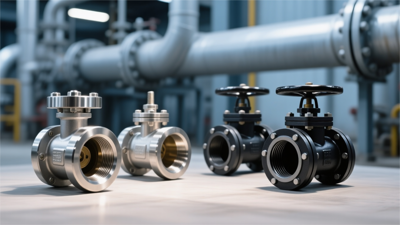
Warehouse stock is managed through a full color-coding system. Yellow indicates A105 carbon steel, blue indicates F304 stainless steel, and red indicates F51 duplex steel. This reduces the chance of issuing the wrong material to one in one hundred thousand.
Even the fasteners must be fully traceable. The drawing specifies B7 alloy steel for the 12 M16 stud bolts used on the valve cover. A Brinell tester leaves a 3.2 mm indentation on the bolt end face.
The reading is 285 HBW, which falls within the required range of 201 to 321 HBW. The nuts have been hot-dip galvanized, and the coating thickness measures 45 μm.
- The heat batch number can be traced back to a melt made three months earlier
- Quench-and-temper heat-treatment curves are uploaded to the server and retained for ten years
- Every bolt is accompanied by a tensile test report issued by an independent laboratory
When the factory serial number V2504-001 is entered into the ERP system, 15 pages of PDF scans load within 3 seconds. Casting records, forging records, O-rings, springs, nuts, and the full set of source documents all appear on screen.
There are no signs of patchwork edits or backfilled revisions. The foreign plant auditor reviews the traceability chain, checks the approval box, and a purchase order for 500 high-pressure ball valves is placed on next month’s production schedule.


")