
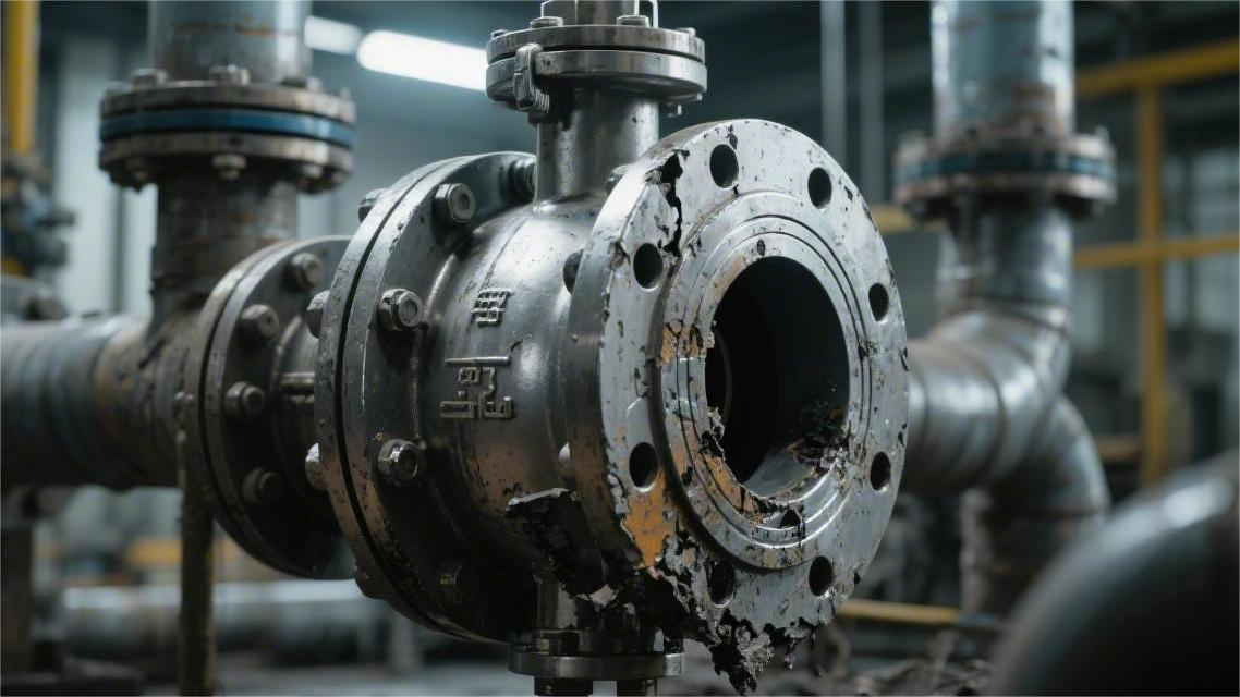
Industrial ball valves in severe service most often fail because seal wear exceeds 0.2 mm/year, pressure fluctuations go beyond ±20% of the design value, or materials are mismatched.
In H₂S-containing service, for example, failing to use duplex stainless steel can sharply accelerate corrosion.
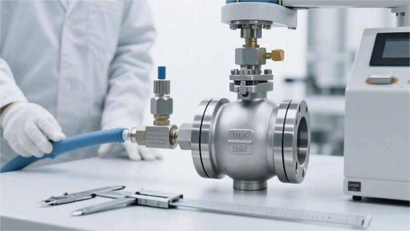
During operation, torque variation should be monitored regularly; if it rises by 15% or more, the valve should undergo seal retesting in accordance with API 598 to prevent failure.
Seal Wear
Solid Particles
In a 50 mm industrial pipeline, crude oil rushes through at 8.5 m/s. The fluid carries entrained particles, including quartz sand and rust flakes ranging from 15 microns to 2 mm.
As the crude approaches a half-open ball valve, the flow area drops sharply from 1,960 mm² to less than 400 mm². The narrowed passage drives the flow velocity up to four times its original speed.
The suspended quartz sand gains enormous kinetic energy. With a Mohs hardness of 7, these grains behave like miniature armor-piercing projectiles when they strike a soft plastic surface with a hardness of only Shore D55.
Microscopic observation captures the force of impact. A single 0.5 mm sand particle, driven by a 3.2 MPa differential pressure, can instantly tear a groove 0.08 mm deep into an otherwise smooth surface.
Common destructive particles found in pipelines include:
- Sharp quartz sand (hardness 7)
- Highly abrasive alumina powder (hardness 9)
- Large rust scale flakes (hardness 5 to 6)
- Crystalline salts prone to clogging (hardness 4)
When fluid carrying hard solids flows through the valve, foreign matter is forcibly wedged between the ball and the seat. A gap of just 0.1 mm can result in a leakage rate of 45 liters per hour under a 2.0 MPa water pressure condition.
The escaping fluid acts like a wire-cutting jet. Following the initial scratch, the high-speed stream erodes deeper along the damaged path, and a tiny 0.08 mm pit can expand into a 2.5 mm-wide deep groove within 48 hours.
During valve actuation, particles attached to the ball surface are dragged into the sealing interface. As the ball rotates 90 degrees under a torque of 150 N·m, those particles cut into the surface like lathe tools.
A natural gas master valve that had been in service for 120 days was dismantled for inspection. Its soft seat ring, originally 6.35 mm thick, had been abraded by sand and gravel until the thinnest section measured only 1.2 mm, with dense scratches deeper than 0.5 mm across the surface.
These scratches destroy the protective barrier. Fine powder packs into the grooves and becomes compacted under pressure. As a result, the coefficient of friction rises dramatically from 0.04 at the factory to above 0.3.
As friction multiplies, the air pressure required by the pneumatic actuator climbs from 0.4 MPa to 0.65 MPa. If the air supply becomes insufficient, the ball can stall in a half-open position at 45 degrees.
A stalled ball then faces severe erosion. The fluid forms a jet at over 40 m/s, and the entrained metal fragments can pit a 316 stainless steel ball surface densely within just 3 minutes.
Laboratory testing has quantified particle-related loss. In a slurry with a solids content of 3%, after 5,000 continuous operating cycles, conventional nylon components showed a mass loss rate of 18.5%.
Service life under abrasive conditions varies significantly by material:
- Standard soft plastic parts: surface roughness fails after 24 hours
- Carbon-fiber-reinforced parts: grooves appear after 150 hours
- PEEK hard plastic: deformation reaches 5% after 300 hours
- Surface-hardened metal parts: maintain zero leakage for 1,200 hours
A refinery catalytic cracking unit switched to a metal seat housing coated with tungsten carbide. The coating thickness was controlled at 0.2 to 0.3 mm, with a hardness of HV 1100.
Under particle impact at the same flow velocity, the hardened surface showed only 0.005 mm micro-scratches. The high-speed sand particles rebounded on impact and were deflected toward the inner flow channel wall.
Ultrasonic thickness inspections showed that in a water injection pipeline with a sand content of 5‰, a 12 mm carbon steel elbow wore down to the retirement threshold of 8.4 mm within 18 months.
Installing a Y-strainer 1.5 meters upstream helps reduce the impact. A 40-mesh stainless steel screen with an aperture of about 0.4 mm can intercept large, hard particles.
Increasing pipe diameter also reduces fluid velocity while maintaining the same flow rate of 200 m³/h. Expanding the diameter from 80 mm to 100 mm lowers the medium velocity from 11 m/s to 7 m/s.
Lower velocity reduces kinetic energy on a square-law basis. When the speed falls to 63% of the original value, particle impact energy drops to 40%, and the wear rate decreases significantly.
Equipment adjustments that help reduce fluid damage include:
- Installing a desander upstream to remove particles above 50 microns
- Increasing pipeline cross-sectional area to reduce initial fluid velocity
- Adjusting the pump inverter to lower supply pressure by 0.5 MPa
- Switching to a full-port design to minimize internal turbulence
Even with filtration, micron-scale fine dust inevitably remains in the pipeline. These tiny crystals behave like polishing compound, settling silently along the contact line between the ball and the seat.
With every rotation, a 0.01 mm layer of fine particles is compressed into the polymer structure. After six months of penetration, a white material can turn dark gray and become as brittle as cast iron.
When such an embrittled component contracts under nighttime temperatures of -15°C, the internal stress can exceed its 15 MPa tensile limit. With an audible crack, a through-fracture as long as 40 mm can form.
High-pressure gas at 6.0 MPa then escapes through a 0.2 mm crack. The violent vortex formed in the rear cavity can literally tear the entire seat assembly out of its retaining groove.
Dry Friction & Torque Variation
Pure high-pressure nitrogen flows continuously through a 4.0 MPa pipeline network. The automated control program requires the valve to open and close 800 times per day.
Because the gas contains no moisture or oil at all, the polished 316L stainless steel ball and the PTFE seat operate in a completely dry rubbing condition.
Those 800 daily cycles generate substantial heat. Infrared thermography shows that the local contact temperature can rise from 25°C to 85°C within two hours of operation.
At elevated temperature, the soft plastic surface starts to soften and smear. A plastic film roughly 0.005 mm thick can be pulled off and adhere tightly to the hot metal ball.
The mirror-finished steel ball, originally with a roughness of Ra 0.2, becomes covered with irregular patches of transferred polymer. The once-smooth sliding surface turns rough and broken.
Laboratory testing reproduced the resistance change. Under liquid lubrication, the sliding friction coefficient was only 0.05. In a dry, adhesive condition, it rose sharply to 0.28.
The pneumatic actuator was factory-rated at 120 N·m. Once the ball became coated with polymer buildup, it required 210 N·m just to start moving.
With only 0.5 MPa air pressure delivered to the cylinder, the actuator could no longer provide enough thrust. A shutoff action designed to complete in 2 seconds was stretched out to 7 seconds.
Maintenance logs recorded the torque increase under different dry-service conditions:
| Medium in Pipeline | Continuous Running Days | Total Cycles | Initial Torque (N·m) | Final Torque (N·m) | Valve Condition |
|---|---|---|---|---|---|
| High-purity argon | 45 days | 12,000 | 85 | 190 | Severe sticking |
| Dry instrument air | 60 days | 9,500 | 90 | 175 | Sluggish movement |
| High-purity isopropanol | 30 days | 15,000 | 110 | 260 | Completely seized |
When the ball seizes and cannot rotate, the externally applied torque is transferred directly to the stem. A solid steel rod 18 mm in diameter is then forced to absorb the lateral shear load.
Metal has its own failure limit. Once the applied torque reaches 280 N·m, the rod can no longer withstand the load and takes on a permanent twist of 3 degrees.
A 3-degree mechanical deformation misaligns the flow port inside the ball. Externally, the indicator still appears to show full open, but inside, a 4 mm-thick metal edge remains in the center of the flow path.
That 4 mm obstruction creates violent turbulence. As the fluid rushes past, local pressure collapses, and tiny bubbles implode against the metal wall at a rate of 10,000 times per second.
In motor-operated valves, sticking can trigger even more serious electrical consequences. A motor rated at 2.5 A may pull as much as 6.8 A in an attempt to overcome the sticking point.
If the thermal overload protector fails to cut power within 15 seconds, the windings in a 380 V motor can overheat to the point of insulation burnout.
Frequent cycling leaves the equipment no time to cool. When the valve operates once every 45 seconds, accumulated thermal expansion and contraction can consume 0.15 mm of internal running clearance.
The reduced clearance grips the metal ball like a vise. Contact pressure at the interface can exceed the design limit of 15 MPa, imprinting deep permanent marks into the polymer seat ring.
Plant inspectors rely on several key indicators to catch early signs of worsening resistance:
- Motor current rising by more than 15% over a week of continuous duty
- Pneumatic full-stroke travel time exceeding the acceptable limit of 3.5 seconds
- Metal-to-plastic scraping noise reaching 85 dB at 0.5 meters
- Transverse wear marks as deep as 0.5 mm on the stem connecting pin
- Air supply pressure dropping below the normal floor of 0.45 MPa at the moment of actuation
Changing the internal load path can greatly reduce sticking. In a trunnion-mounted ball design, the 5-ton lateral thrust generated by high-pressure flow is transferred to the upper and lower trunnions instead of being borne directly by the seat.
A wave spring behind the seat provides approximately 200 kg of thrust, keeping the seat in light contact with the ball. This prevents high-pressure gas from forcing the ball hard against the plastic surface.
A premium valve body may include a 2 mm grease injection passage on the side. By injecting 10 grams of synthetic fluorosilicone grease every 30 days, maintenance personnel can keep the coefficient of friction below 0.08.
Adding 15% graphite powder during engineering plastic processing also creates a self-lubricating material. As the surface wears, new solid lubricant is continuously exposed.
Replacement records from a polysilicon plant confirmed the benefit. After dry chlorine service was switched to graphite-filled components, operating torque remained stable and the maintenance-free interval increased from 45 days to 14 months.
Temperature & Chemistry
A pipeline carrying 220°C hot heat-transfer oil runs continuously. The white PTFE seat ring inside the compact valve cavity is subjected to extreme thermal stress. Once the temperature exceeds the 200°C threshold, the plastic begins to soften and its hardness drops from Shore D60 to D30.
Even at a relatively low pressure of only 0.5 MPa, the softened plastic can be squeezed by the stainless steel ball and extrude into tiny clearances like dough under pressure.
After only 150 hours of operation, the originally 5 mm-thick seal ring can be compressed by 1.2 mm. The extruded portion is then torn into more than ten white strands, each as long as 3 cm, by the fast-moving oil.
At an LNG receiving terminal, the environment is the opposite extreme. Liquid at -196°C flows through insulated piping, and everything contracts under cryogenic conditions. A plastic component with an internal diameter of 100 mm can shrink by 4.5 mm in circumference.
At such low temperature, elastic polymers can become as brittle as glass. A minor pressure fluctuation in the line, combined with a 3.0 MPa water hammer impact, can cause the embrittled seat to crack instantly, forming more than ten network cracks each about 0.5 mm wide.
Those cracks become major leakage paths. Gas with vaporization energy escapes violently through a 0.2 mm gap, and a detector placed 2 meters away may measure a flammable gas concentration as high as 15% around the leak.
In a chemical plant, a pipeline carrying 98% sulfuric acid presents a different challenge. The strong acid penetrates every possible opening and forces its way into the molecular structure of fluororubber. After 30 days of immersion, the volume of the elastomer can swell by 18%.
The swollen seal completely blocks the ball’s rotation path. When the pneumatic actuator forces the valve to move, 150 N·m of torque can tear off a chunk of rubber the size of a fingernail.
At natural gas wellheads carrying 15 MPa high-pressure gas, small gas molecules are forced deep into the elastomer. If operators hit the emergency vent and reduce internal pressure from full operating pressure to atmospheric pressure in just 2 seconds, the trapped gas cannot escape fast enough.
Instead, it explodes microscopically inside the material. When a failed seal is cut open, its black cross-section is found to be full of burst cavities around 0.2 mm in size.
Laboratory records show the destructive effects of different media on sealing materials:
- 25% sodium hydroxide at 80°C can embrittle ordinary rubber in 5 days
- Special components used in liquid chlorine service can lose 40% of tensile strength after 3 months
- Strong polar organic solvents can strip off a 0.1 mm functional coating within 15 days
- 150°C steam at 1.2 MPa can easily destroy a nylon seat
When 150°C high temperature is combined with 60% nitric acid, the damage becomes exponentially more severe. Heat dramatically accelerates chemical attack, and even specialty plastics that can resist acid at room temperature may fail completely within 72 hours.
Once the acid penetrates the 0.5 mm protective layer, it reaches the stainless steel ball underneath through microscopic pathways. Ultrasonic thickness measurement then reveals a wide honeycomb-like area of corrosion pits up to 0.8 mm deep.
In extremely aggressive service, the only viable solution is to change the material system. Conventional plastics are replaced with FEP, whose melting point rises to 290°C and whose tensile performance remains stable even under a 2.5 MPa differential pressure.
A metal bellows then takes over the sealing function. Special alloy steel sheets 0.3 mm thick are formed into multiple convolutions, relying on their own elastic deformation to stay tightly pressed against the polished ball surface.
The replacement standard for severe-service components is correspondingly strict:
- At -196°C, all parts must be replaced with cryogenically treated PCTFE, with shrinkage limited to 0.5%
- In heat-transfer oil pipelines above 300°C, plastic is completely eliminated and replaced with graphite/stainless steel wound gaskets
- For 98% sulfuric acid, the ball surface is coated with Hastelloy C276
- In high-pressure gas wells prone to explosive decompression, anti-blowout polyurethane parts with hardness above Shore A90 are required
Even when using a full-metal seat, thermal expansion still has to be considered. A steel pipeline 200 meters long can undergo a linear expansion of 40 mm when heated by 200°C.
That expansion pushes the valve body forward, transmitting deflection stress through the pipe wall. The internal ball can be forced 0.15 mm off center, leaving a long scratch on the tightly matched metal sealing surface.
To absorb thermal growth, pipeline designers weld bellows expansion joints with spring tie rods on both sides of the valve. These joints can absorb 30 mm of movement and reduce the additional compressive load on the internal components by 60%.
Once these measures are in place, the flow meter stabilizes. 120 m³/h of concentrated nitric acid can pass smoothly through the valve, while the pressure gauge remains steady at 4.5 MPa with no abnormal oscillation.
Pressure Fluctuation
Water Hammer
In a 600 mm steel pipeline, fluid flows at 3.5 m/s. If a ball valve closes suddenly in 0.2 seconds, the moving liquid mass—amounting to tens of tons—has nowhere to go. Its kinetic energy is converted almost instantly into impact on the pipe wall and valve body. Within just 10 milliseconds, internal pressure can jump from a normal 1.6 MPa to 22 MPa.
The high-pressure surge wave reverses along the steel wall at 1,430 m/s. The tightly sealed metal pipeline expands outward on a microscopic scale. The alloy steel bolts connecting the valve are among the first components to be hit, experiencing tensile stresses as high as 650 MPa under the 22 MPa pressure surge. At the thread engagement, a minute slip of 0.05 mm can occur, forcibly opening the flange gap.
That huge thrust is then transmitted inward through the metal structure, where the internal drive components are heavily impacted. A 45 mm stainless steel stem can be subjected to a torsional load more than three times its rated capacity, causing internal misalignment and invisible fatigue cracks at the joint edges.
The soft seal ring, responsible for blocking leakage, also suffers severely. The high-pressure wave carries rust particles from the bottom of the pipeline and blasts them against the PEEK sealing surface like shotgun pellets. The seal is plastically deformed under the one-directional force, leaving a permanent indentation of 1.2 mm. The original tight contact between the ball and the seal is then torn open into a 0.3 mm leakage gap.
To identify high-pressure impact damage, field maintenance teams monitor the following physical changes:
- Pressure instruments capturing rapid surges between 0 and 50 MPa
- Pipe supports vibrating at 15 to 30 Hz
- Retaining nuts loosening by 0.5 to 1 turn
- Flaw detectors showing dark indications penetrating 15% of the wall thickness
Engineers mitigate water hammer through physical intervention in the piping layout, creating a buffer zone for trapped energy. A surge tank fitted with a rubber bladder may be installed 5 meters upstream of the valve and precharged with 1.0 MPa nitrogen. When the pressure wave arrives, the bladder compresses and absorbs 60% of the destructive energy. Downstream, rigid piping can be replaced with 304 stainless steel flexible bellows.
Technicians also set the spring-loaded relief valve opening pressure precisely at 1.8 MPa. When internal pressure exceeds that value, the spring lifts within milliseconds, discharging 120 liters per second of high-pressure liquid. Once pressure falls back to 1.65 MPa, the spring reseats the valve. The entire relief event takes only 85 milliseconds.
The operator in the control room can also modify the valve closure logic. The first 80% of the closing stroke is maintained at a normal speed of 150 mm/s to ensure timely isolation. Over the final 20%, the actuator is forcibly slowed to just 15 mm/s.
The improvement is measurable. A 300 mm ball valve without speed control can produce a closing noise level of 112 dB. When the closure time is extended from 1.5 seconds to 4.2 seconds, the measured noise level drops to 78 dB, closer to normal ambient conditions.
Routine operating practice is then formalized into precise action steps:
- Keep the valve slightly open at 15 degrees before starting the pump
- Ramp the inverter at 2 Hz per second
- Increase operating frequency to 50 Hz over 25 seconds
- Inject a polymer drag reducer at a concentration of 5 ppm into the pipeline
These measures reduce frictional resistance against the pipe wall and increase energy dissipation from the surge by 22%. Extreme pressure spikes disappear, component wear is controlled to a safe level of 0.3 microns, and the system returns to stable service.
Sealing Material
A typical white PTFE seat ring is manufactured with a thickness of 5 mm. The heavy metal ball keeps it compressed in the seat groove. When pipeline pressure rises from 0 to 6.8 MPa in just 2 seconds, the originally flat plastic ring can be permanently compressed by 0.2 mm.
When pressure cycles repeatedly between 3 MPa and 8 MPa, the plastic is continuously stressed. After 24 hours of uninterrupted operation, the originally straight outer edge can bulge outward noticeably. Caliper measurement may show a 4% loss in section thickness.
The compressed plastic then seeks any available escape path and is forced into surrounding clearances. With only a 0.15 mm installation gap between the ball and the metal housing, pressure above 15 MPa can extrude the plastic edge into the gap. Once the pressure drops, the exposed burr is sheared off by the sharp metal edge and carried away by the fluid.
| Material | Maximum Temperature | Minimum Pressure Rating | High-Pressure Damage Pattern |
|---|---|---|---|
| PTFE | 180°C | 14 MPa | Outer edge extrudes and deforms by 0.2 mm |
| Modified PEEK | 260°C | 100 MPa | Deep internal cracking develops |
| Nylon | 150°C | 80 MPa | Absorbs fluid and swells by 2% |
A heat-transfer oil pipeline in a chemical plant operating at 260°C may switch to a harder modified PEEK. Although it can withstand 100 MPa, repeated high-pressure pulsation at 40 cycles per minute can still break polymer chains internally, causing the material to lose its elastic recovery.
A rapid pressure drop in a gas pipeline can trigger explosive decompression. Natural gas at 10 MPa is forced into microscopic pores inside the material. If the operator opens the vent valve and drops pressure to 0.1 MPa within 3 seconds, the trapped gas can expand by a factor of 100.
The smooth plastic surface is then instantly covered in dense blisters. The largest bubbles can reach 5 mm in diameter, bursting with faint popping sounds and leaving deep craters behind. This is why certified anti-explosive-decompression materials become a mandatory requirement. After 50 high-pressure cycling tests, the surface blister rupture rate of these upgraded materials remains below 5%.
Plant maintenance records show the extent of damage different materials suffer under high pressure:
- White soft plastic ring: section thickness loss exceeds 4%
- Hard PEEK: grooves 0.8 mm deep appear on the contact surface
- Rubber O-ring: dense surface craters up to 5 mm in diameter
- Nylon dust ring: abnormal volumetric swelling of 2%
In crude oil lines carrying large amounts of quartz sand around 50 microns in size, a sudden rise in pressure can drive local flow velocity up to 12 m/s. The particles are pressed between the ball and the soft seat and act as micro-cutting tools. After 300 hours of operation, a hard plastic ring may develop a circumferential groove as deep as 0.8 mm.
For ultra-high-pressure severe service, abandoning soft materials entirely becomes the preferred solution. Technicians use a high-velocity flame spray process to apply tungsten carbide powder to the stainless steel ball, creating a hard armor layer 0.3 mm thick. Rockwell hardness measurements reach HRC 68 to 72.
The seat is also replaced with a metal ring coated in tungsten carbide alloy. Machinists lap the mating surfaces to a roughness of 0.1 micron. Under spring force, the two hard metal surfaces remain tightly pressed together. After 3,000 high-frequency on-off cycles, total metal wear remains below 0.02 mm.
Spring force also compensates continuously for small pressure drops in the line. During assembly, workers use a torque wrench to preload the wave spring to 50 kg. Even if fluid pressure inside the line drops rapidly to a low point of 0.5 MPa, the stored spring force still keeps the metal ring pressed tightly against the ball to close the gap.
Instrument readings on the test bench document the performance limit of the metal-seated assembly:
- Pressure pump gauge: 22.5 MPa
- Seal-hold timer: 120 seconds
- Collected water in the measuring cup: no more than 6 drops per minute
- Spring preload tester: axial thrust maintained above 50 kg
In the standard hydrostatic test, room-temperature water is pressurized into the closed ball valve body until the gauge reaches 22.5 MPa. The inspector times a 120-second hold. The thick metal wall emits only a faint metallic rubbing sound under the massive outward force.
There must be no visible abnormal liquid level rise in the collection cup below the test stand. Maximum allowable leakage is strictly limited to 6 drops per minute. Metal-seated assemblies that pass this extreme-pressure test are marked with an acceptance stamp and packed for delivery to oilfield pipelines to replace soft-seated valves crushed by high pressure.
Pressure fluctuations in high-temperature steam systems bring combined stress from both pressure and temperature. Superheated steam at 320°C flows through the pipe at 45 m/s, while pressure fluctuates irregularly between 5 MPa and 8 MPa. A 3 mm flexible graphite gasket is installed between the valve body and bonnet flange.
During manufacturing, 0.1 mm stainless steel corrugated foil is inserted into the graphite layers. Pure graphite is brittle, but the metal reinforcement increases the tensile resistance of the gasket by 400%. Even after six months of cyclic pressure loading, the leak detector continues to read below 0.01 ppm.
Cavitation & Flashing
Water at 20°C flowing through a ball valve opened only 15% is forced through a narrow crescent-shaped metal gap. The velocity jumps from 2 m/s to 28 m/s, and pressure drops below 2.34 kPa. Even though the water temperature remains unchanged, violent vaporization occurs and millions of microbubbles form every second.
A high-speed camera operating at 100,000 frames per second captures dense clouds of bubbles clinging to the back side of the stainless steel ball. These fine bubbles, only 0.05 to 0.2 mm in size, occupy the flow path. In an instant, the apparent volume of the water can increase by 800 times.
An ultrasonic thickness gauge transmitting data every 24 hours shows that the bottom of a metal wall originally 12 mm thick can be worn away at a rate of 0.15 mm per day by the high-speed vapor-liquid mixture.
Those bubbles race downstream and scour everything in their path. The aerated high-velocity stream hits the metal wall like a sandblaster. Within just 48 hours, the polished surface of a 316L stainless steel component can become badly mottled, and roughness can jump from 0.4 microns to 3.2 microns.
As the water exits into a wider downstream pipe, velocity decreases and pressure rises again above 2.34 kPa. The newly formed bubble cloud is then crushed by the surrounding liquid. Under a surrounding pressure of 1.5 MPa, the bubbles collapse inward almost instantaneously.
During collapse, the gas temperature inside the bubbles can soar to 5,000°C. When millions of bubbles implode at the same time, they release their energy as microjets traveling at up to 400 km/h.
These microjets behave like countless microscopic chisels. With local impact waves as high as 1,000 MPa, they strike the metal ball surface violently. Even the hard stainless steel surface cannot withstand this repeated attack, and the previously smooth surface becomes covered with needle-like pits.
Under the microscope, the damaged metal is devastated. The surface is full of craters 0.02 to 0.1 mm deep, resembling a honeycomb eaten away from the inside.
Workers can often identify the problem by sound alone. Standing 2 meters away, they hear a sharp crackling noise like gravel churning in a mixer. A sound level meter shows 95 dB, while a metal nameplate on the flange vibrates more than 50 times per second.
Relentless micro-impacts eventually destroy sealing performance. Each time the pitted ball rotates, it grinds against the PTFE seat like coarse sandpaper. After only 150 open-close cycles, a 5 mm plastic ring can lose 1.2 mm of thickness, allowing high-pressure water to leak straight through the gap.
Plant maintenance crews typically make several major modifications:
- Replace the old valve with a special sleeve insert featuring three pressure-reduction stages
- Break the excessive water pressure into safer steps of 1.5 MPa, 1.0 MPa, and 0.5 MPa
- Reshape the internal flow path so water velocity stays below 8 m/s
- Overlay the most exposed impact zone with 2.5 mm of hard alloy weld metal
The staged pressure-reduction design stabilizes the pressure floor inside the line. After three months of continuous service, ultrasonic testing of the pipe wall shows a stable waveform, with no new cracks found within a 50 mm inspection zone. The “gravel mixer” noise at 95 dB finally disappears.
Engineers also revise the control logic so the valve can never close below 25% open. If instruments detect flow dropping below 150 m³/h, the system immediately opens a parallel bypass line.
This prevents the water from being forced through an excessively narrow gap. The pressure differential across the valve is kept within a safe limit of 0.8 MPa, and vibration amplitude drops back to 0.5 mm/s. The system can then transport 2,400 tons of industrial water per day and run for 4,000 hours without measurable metal loss.
Rising water temperature further intensifies the damage. When outdoor summer temperature approaches 40°C, the vaporization threshold of industrial water rises to 7.38 kPa. Even a slight temperature change can triple bubble formation. Field operators may respond by increasing cooling tower fan speed from 750 rpm to 1,200 rpm.
Material Mismatch
Chemical Corrosion
When pH drops below 3, or free chloride concentration exceeds 1,000 ppm, the oxide film only a few microns thick on carbon steel can break down within minutes. A low-cost carbon steel valve may still handle 98% sulfuric acid in a static storage tank, but once the liquid enters the narrow flow path of a ball valve and flow velocity exceeds 1.5 m/s, the protective ferrous sulfate film is stripped away. The exposed base metal can corrode at a rate of at least 5 mm per year, so a 15 mm wall may lose structural integrity within just a few months.
In seawater desalination or dyeing wastewater lines, 304 stainless steel exposed to warm water at 60°C containing 300 ppm chloride can rapidly develop dark pits. These pits may grow 2 to 3 mm deep and penetrate along the metal grain boundaries.
Resistance to chloride attack is usually judged by PREN:
- 316L: PREN 23 to 28, suitable only for mildly saline water
- 2205 duplex stainless steel: PREN 35, suitable for normal seawater
- 2507: PREN above 40, able to withstand 5,000 ppm boiling chloride-containing water
- In free chlorine service, Grade 2 titanium is required
Even adding just 5% methyl ethyl ketone or acetone during cleaning can cause a conventional fluororubber O-ring to swell like a sponge. Volume may increase by more than 15%, forcing the seal out of its metal groove. Each opening and closing stroke then causes the hard metal ball to shear away the swollen elastomer.
In refinery desulfurization pipelines, H₂S is especially dangerous. Hydrogen atoms generated by sulfide corrosion diffuse into the metal lattice and gather into gas pockets. The internal pressure can rise to several thousand MPa, tearing hidden step-like cracks into a solid metal stem from the inside.
To resist H₂S damage, several hard requirements are imposed:
- Carbon steel grain size must be finer than ASTM No. 7
- Hardness of pressure-containing components must remain below HRC 22
- Stainless steel hardness must not exceed the allowed limit
- B7M high-strength bolts must be hardness-tested 100%
Where multiple acids and alkalis are mixed in one waste stream, no single metal is enough. Plants often thermally bond an internal lining of FEP or PFA, 3 to 5 mm thick. As long as temperature does not exceed 150°C, that lining can isolate most commercial chemical solvents from the metal substrate completely.
However, chlorine and hydrogen fluoride molecules are extremely small. Under 0.8 MPa, trace gas can permeate through polymer chain gaps and condense behind the lining into acidic liquid. That acid then eats through the cast iron backing, causing the unsupported plastic lining to blister and delaminate in large sections, eventually blocking the pipeline.
To prevent this, manufacturers modify the process:
- Increase lining thickness from 3 mm to 5 mm
- Drill two or three 2 mm vent holes in the cast housing
- Increase the density of the modified lining by 20%
- Apply a 0.5 mm anti-corrosion primer to the cast steel cavity
During batch changeovers, operators may flush the line with 10% caustic soda or inject 180°C steam. Surfaces designed only for weak acid service can be stripped by hot alkali, and the roughness of the seat sealing face may jump from Ra 0.4 to Ra 3.2, leading to leakage within minutes.
Thermal Cycling
Pure PTFE expands about ten times faster than WCB carbon steel. If a carbon steel valve fitted with a PTFE seat is heated from 20°C to 200°C, the plastic ring tries to expand but is trapped tightly between the stainless steel ball and the steel body.
The polymer cannot compete with steel rigidity, so compressive stress rises above 15 MPa. The originally rounded profile is flattened and undergoes irreversible deformation.
When the system cools back down to 20°C, the steel contracts. The deformed PTFE does not recover, leaving a gap of 0.2 mm between the stainless steel ball and the seat, which allows leakage.
Carbon-fiber-filled PEEK does not soften even at 260°C, but its rigidity becomes a disadvantage when the temperature drops because it has almost no elastic recovery. To maintain sealing, at least 3.0 MPa line pressure is required to force the ball against the PEEK seat.
Above 260°C, plastics are no longer viable, and sealing depends on metal-to-metal contact. At 400°C, any lubricating film on the metal surface is burned away. A 316 stainless steel ball rubbing directly against a metal seat can shed large amounts of metal debris and score grooves 0.5 mm deep.
To address this, plants use a high-velocity spray process to apply tungsten carbide. The resulting 0.3 mm coating reaches about HRC 68, hard enough to scratch glass and stable even under repeated friction at 500°C.
Problems can still arise during thermal shock. If 50°C cold water is suddenly introduced into a 400°C steam line, the temperature can collapse within 10 seconds. The 316 stainless steel substrate contracts quickly, but the 0.3 mm tungsten carbide coating contracts more slowly.
This mismatch tears the coating apart, creating fine spiderweb cracks that eventually flake into the line. Replacing the coating with Stellite 6 weld overlay solves the issue because its thermal expansion behavior closely matches stainless steel.
| Material | Temperature Limit | Thermal Expansion Coefficient | Failure Caused by Thermal Cycling |
|---|---|---|---|
| Pure PTFE | 200°C | 120 × 10^-6/K | Shrinks on cooling and opens a large leakage gap |
| Carbon-fiber PEEK | 260°C | 47 × 10^-6/K | Becomes rigid after cooling and loses spring-back |
| 316 stainless steel, polished | 600°C | 16 × 10^-6/K | Dry galling and metal pickup above 400°C |
| Tungsten carbide coating | 550°C | 5 × 10^-6/K | Cracks and spalls under cold-water shock |
In LNG pipelines, -196°C causes all materials to contract severely. In a 10-inch valve, the outer steel body can shrink by about 3.5 mm, forcing the internal parts out of alignment.
Standard WCB carbon steel becomes brittle below -29°C. At -100°C, even a light impact with a wrench can shatter it like glass. Specifications therefore require CF8M stainless steel or LC3 low-temperature steel, which must absorb at least 27 joules in a Charpy impact test at -196°C.
Conventional springs hidden behind the seat become brittle and fracture easily at -196°C. Replacing them with Inconel 718 wave springs makes it possible to maintain a steady thrust of 500 N even in liquid nitrogen conditions, keeping the seat firmly pressed against the ball.
Externally exposed stems in cryogenic service often develop heavy frost. When operators force the handle, sharp ice crystals can grind away the 0.1 mm soft graphite packing around the stem like abrasive paper.
To avoid this, manufacturers add a 150 mm stem extension, moving the packing box away from the -196°C cold zone into ambient air at around 5°C. In this configuration, the packing stays unfrozen and the valve can cycle 5,000 times without gas leakage.
Thermal cycling also affects bolting first. A flange tightened to 800 N·m at room temperature may be exposed to 350°C heat-transfer oil. The row of B7 alloy bolts can elongate by 0.15%, instantly loosening the gasket compression.
When the system cools back down to 10°C, the bolts do not fully recover their original clamping force. The initial 800 N·m preload may fall to 300 N·m. If the graphite gasket is no longer sufficiently compressed, 2.0 MPa hot oil can spray out through the flange gap as soon as the pump restarts.
To solve this, specifications require three stacked disc springs under each nut. These springs provide 2.5 mm of movement allowance and maintain a minimum clamping force equivalent to 600 N·m as the bolts expand and contract.
Flexible graphite packing performs well up to 450°C. Once temperature exceeds 500°C, however, even a small amount of oxygen can react with the carbon. A 10 mm graphite ring baked at 550°C for 48 hours may shrink to only 6 mm, leaving a large void in the packing box and allowing toxic gas to leak out freely.
To prevent oxidation, the upper and lower ends of the packing set must be reinforced with wire mesh rings woven from 0.05 mm Inconel wire, which block oxygen ingress.
Electrochemical Corrosion
In cost-driven designs, an ASTM A105 carbon steel body may be paired with a 316 stainless steel ball. Once seawater containing 35,000 ppm salinity flows through, an electrochemical bridge forms immediately.
Measured potential shows carbon steel at -0.85 V and 316 stainless steel at -0.50 V. This 0.35 V potential difference drives the body to dissolve into the water. The corrosion may not be obvious from the outside, but the carbon steel wall underneath can be consumed at a rate of 6 mm per year.
Improper size ratio between dissimilar components can make the problem much worse. A 50 kg stainless steel ball paired with several small carbon steel pins weighing only 20 grams each concentrates the galvanic attack on the tiny pins. Within three months, an originally 8 mm pin can corrode down to only 2 mm.
If the failed housing is cut open, the once-solid joint area often looks like termite-eaten wood. A flat screwdriver can easily punch through it, while the adjacent noble metal parts may still appear almost untouched.
The problem can also develop beneath the packing box. A graphite-filled ring installed under the stuffing box has a potential around +0.25 V. Placed next to a -0.85 V carbon steel body, that 1.1 V difference can eat a circumferential groove 4 mm deep into the seat support.
The only way to interrupt the current path is through insulation:
- Fit 3 mm G10 epoxy-glass sleeves around bolts and bolt holes
- Replace the flange gasket with pure PTFE having resistance above 10^8 ohms
- Force physical separation between the two metals so current cannot pass
Material selection should also follow the galvanic series:
- Keep the potential difference between contacting metals below 0.05 V
- Increase the wetted area of the sacrificial carbon steel part and minimize cathode area so dissolution drops to 0.1 mm per year
- If no good pairing is possible, weld a 2 kg zinc sacrificial anode into the flow path
At the discharge of a high-pressure pump in a seawater desalination plant, water at 8.0 MPa moves fast enough to strip away the thin rust film that would otherwise protect carbon steel. Fresh metal is constantly exposed, so a heavy-walled pipe designed for a one-year service life may develop large perforations within just 45 days.
Conditions are even worse in produced water from oilfields containing H₂S. Sulfate-reducing bacteria colonize corrosion pits, and in black water at pH 6.5, they proliferate rapidly. The sulfides they produce can widen the electrochemical potential difference to more than 0.6 V.
When bacterial activity combines with galvanic corrosion, the damage multiplies. A pipe wall that looks smooth from the outside may already be hollowed out underneath by gourd-shaped internal cavities, and ultrasonic thickness readings across the surface will light up in alarm.
To resist this mixed attack, operators often have no choice but to apply a high-grade barrier coating. A 0.4 mm epoxy phenolic lining is sprayed onto the carbon steel inner wall and cured at 200°C. After curing, the coating can withstand a 15 kV holiday test, completely isolating seawater from the metal.
But any coating defect is dangerous. Even a pinhole only 0.1 mm wide can focus the entire corrosion current on one spot. A current of just a few hundred milliamps can attack the exposed metal so aggressively that a 20 mm thick solid iron wall is penetrated from start to finish in only two days.
Wrong fastener pairing can also ruin the whole design. If B7 alloy bolts are matched with 304 stainless steel nuts on an exposed coastal structure, salt-laden air leaves behind a continuous saline film about 0.05 mm thick.
Before a single rainy season is over, the fine threads beneath the B7 bolts may already be eaten flat. When maintenance crews try to remove them with a 1-meter breaker bar, a 24 mm bolt can snap cleanly like brittle candy.
On offshore platforms, material defense must be built aggressively. Bolts and nuts are often changed to Monel 400, whose electrochemical potential is closely matched. To resist salt spray and galling, the threads are then coated with 5 mm of molybdenum disulfide anti-seize compound. With this approach, even after ten years in marine atmosphere, the joints can still be disassembled smoothly.
A stainless steel stem inserted into the slot of a duplex steel ball may leave a crevice only 0.05 mm wide. Salty dirty water trapped there becomes stagnant, oxygen is depleted, and the local chemistry turns acidic.
- The pH inside the dead zone can fall to around 2.0
- The acid combined with a small galvanic potential can pit the slot surface heavily
- The tight connection can wear into a 2 mm clearance, so the external handle rotates by more than 30 degrees while the ball inside does not move
- The only reliable fix is to machine the mating parts from the same alloy bar stock, eliminating both galvanic mismatch and crevice corrosion risk


")