
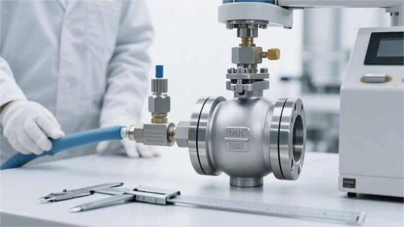
When purchasing industrial ball valves, focus on verifying that the hydrostatic test reaches 1.5 times the design pressure, the pneumatic sealing test shows zero leakage, the sealing surface finish is controlled to ≤ Ra 0.8 μm, and critical dimensional tolerances are held within ±0.05 mm.
The opening and closing torque and concentricity should also be rechecked under the API 598 inspection procedure to ensure stable installation.
Pressure Testing
Shell Strength Test
If the metal contains shrinkage cavities or inclusions above Grade 2, those weak spots can rupture and leak as soon as the body is subjected to hydrostatic pressure at 1.5 times normal working pressure.
During the test, the ball valve must be kept in a half-open position. Workers use heavy-duty blind flanges to seal both ends of the valve completely. Bolt tightening is also strictly specified. For example, when testing an 8-inch Class 300 carbon steel ball valve, alloy steel bolts are required, and a torque wrench is typically set between 600 and 800 N·m.
Water is then filled into the valve cavity, and all trapped air must be fully vented. An air-release valve is installed at the highest point of the body, and clean water is introduced at a flow speed of 0.5 m/s. Only when the discharge at the vent stops producing bubbles is the valve considered completely filled. Even a small amount of trapped air can cause the pressure gauge needle to fluctuate and distort the test reading.
The test water temperature cannot be too low or too high and is generally controlled between 5°C and 50°C. Below 5°C, steel becomes brittle. For stainless steel valves, purified water must be used, with chloride ion content kept below 50 ppm to prevent corrosion.
- Blind plugs / blind flanges: must meet the standard minimum thickness requirement
- Sealing O-rings: high-pressure fluororubber capable of withstanding 42 MPa maximum hydrostatic pressure
- Test water quality: high purity, with conductivity controlled within 20 μS/cm
- Low-temperature steel: must be conditioned at room temperature for 4 hours before pressure testing
Once the pump starts, the pressure gauge needle begins to rise, but the pressurization rate cannot be too fast. It must not exceed 1.5 MPa per second. For a Class 600 ball valve rated for 10.0 MPa, the test pressure must be driven up to 15.0 MPa, and the entire pressurization process must last at least 10 seconds.
If the pressure rises too abruptly, the bolts securing the bonnet can deform under the load. Only after the needle has stabilized completely at 15.0 MPa can the worker start timing the pressure hold period. The larger the valve size, the longer the observation period required.
- Below 2 inches: hold and observe for 15 seconds
- 2.5 to 6 inches: hold and observe for 60 seconds
- 8 to 12 inches: hold and observe for 120 seconds
- 14 inches and above: hold and observe for 300 seconds
During this period, the inspector uses a high-intensity flashlight and a long-handled inspection mirror to examine the valve body from all angles. Any visible seepage, misting, or even the slightest “sweating” on the shell is enough to fail the valve. On sand-cast valves, special attention is paid to joints and riser areas, where wall thickness can sometimes be 12.5% thinner.
There is also packing around the stem to prevent leakage. If it is not compressed properly, problems appear immediately. On high-pressure valves such as Class 900, hydrostatic testing at 22.5 MPa generates several tons of outward force. Even 1 mm of packing deformation can cause water droplets to emerge from the gland area.
On large forged steel ball valves with 24-inch openings, the body cavity can hold several cubic meters of water, and filling plus pressurization alone can take most of a day. The pressure gauge is mounted at the highest point of the blind flange. Its dial must be at least 100 mm in diameter, and its accuracy class must meet Class 1.6.
Pressure gauges cannot be chosen casually. The full-scale range must be between 1.5 and 4 times the test pressure. For a 15.0 MPa hydrostatic test, a 25.0 MPa gauge is appropriate, placing the needle in the most accurate central zone of the dial.
- Bonnet gasket edge: watch closely for hanging water droplets
- Shell corners and edges: apply white chalk dust; even slight dampness leaves a dark stain
- Packing gland: watch whether water slowly creeps upward in the gap
- Drain plug: check whether the threaded joint feels completely dry
- Grease injection valve: verify whether the check ball leaks under water pressure
When the hold period ends, the worker slowly opens the relief valve and lets the high-pressure water drop at a controlled rate of 2.0 MPa per second. Natural draining is not enough, because water remains trapped in dead corners. A 0.6 MPa compressed air line is then connected to blow through the valve cavity for 3 to 5 minutes.
Sealing Test
Once the high-pressure hydrostatic shell test is complete, the sealing test begins immediately. The pump raises the pressure on one side of the valve cavity to 1.1 times the normal working pressure. For a Class 600 carbon steel ball valve rated at 10.0 MPa under ambient conditions, the test pressure is raised to 11.0 MPa.
Under API 598, a 4-inch metal-seated ball valve is allowed to leak no more than 8 drops of water per minute. A sheet of white paper or a graduated glass beaker is placed underneath to collect leakage, and 1 mL of water is approximately equal to 16 drops.
For soft-seated ball valves using PTFE, the requirement is much stricter. Under ISO 5208 Rate A, not a single drop of water is allowed to pass. The inspector shines a flashlight along the dry metal outlet for a full 2 minutes. If even the slightest trace of moisture is seen in the reflection, the valve must be disassembled and reworked.
The hydrostatic sealing test is not the end of the process. A workshop compressor then feeds about 0.6 MPa of dry nitrogen into the valve cavity. Gaps that are too narrow for water molecules to penetrate may still allow much smaller gas molecules to escape once the water is removed.
The worker connects a transparent plastic hose with an inner diameter of 6 mm to the valve vent, placing the other end into a beaker filled with clean water. Eyes stay fixed on the submerged hose outlet. For a 2-inch soft-seated ball valve, not even a 1 mm bubble is allowed to appear during the 15-second test period.
- Monitor the beaker surface: even a pinhead-sized bubble within 15 seconds means failure
- Submersion tank method: an 8-inch ball valve weighing half a ton is lowered by crane into 0.3 m of water
- Observe the water surface: a 0.01 mm flaw on the metal surface produces a continuous stream of fine bubbles once submerged
- Explosion shield required: when testing at 0.7 MPa gas pressure, a 10 mm acrylic shield must be installed externally
A double block and bleed (DBB) ball valve used in long-distance pipelines contains two independent metal sealing barriers. Workers inject hydraulic pressure up to 15.0 MPa into the sealed middle cavity. Both flange ends remain open, and inspectors check both sides alternately with an extended inspection mirror. No water trace whatsoever is permitted.
Observation time varies by valve size. The workshop quality control chart clearly lists the minimum inspection times:
| Valve Bore Size (in.) | Minimum Hydro Test Observation Time (s) | Minimum Pneumatic Test Observation Time (s) | Maximum Allowable Leakage (Metal Seat) |
|---|---|---|---|
| ≤ 2 | 15 | 15 | No more than 4 drops/min |
| 2.5 to 6 | 60 | 60 | No more than 12 drops/min |
| 8 to 12 | 120 | 120 | No more than 20 drops/min |
| 14 and above | 120 | 120 | No more than 28 drops/min |
For valves supplied to chemical plants handling highly corrosive acids, customers may require verification to Class VI gas leakage standards. In that case, the simple beaker bubble test is no longer sufficient. The flange outlet must be connected to a dedicated electronic gas flow meter that displays the escaping gas volume in real time.
For a 6-inch valve, the reading must not exceed 0.45 mL/min. That is roughly equivalent to one mung-bean-sized bubble every two-plus minutes. To hold leakage down to that level, the ball surface is polished on a lathe with a diamond tool to below 0.1 μm.
Resident inspectors often insist on reopening and reclosing the valve two or three times before retesting. A pneumatic actuator rotates the ball against the enormous resistance of 11.0 MPa water pressure. As the metal edge sweeps across the plastic seat, several hundred newtons of dry friction are generated instantly.
If the plastic seat ring is shaved by even 0.05 mm, the secondary pneumatic submersion test will produce vigorous bubbling. After the valve passes, the worker removes the internal ball and inspects the compression marks on the nylon seat ring under direct light.
- Compression marks: normal contact width should remain uniform at 3 to 4 mm
- Eccentric machining check: if one side measures 5 mm and the other only 1 mm, the assembly is clearly defective
- Protection against fluid erosion: the narrow side will likely be destroyed by high-pressure flow within six months after installation
A valve that does not leak at 20°C inside the factory is not necessarily safe outdoors in extreme cold. PTFE can shrink by nearly 2% at very low temperature, pulling open gaps that were tightly sealed at room temperature. For pipeline orders shipped to Siberia, the entire valve is placed in a -46°C cryogenic chamber for 24 hours before testing.
Test Medium Specification
The reverse-osmosis water system in the workshop produces more than 5 tons of deionized water every day. When testing 304 or 316 austenitic stainless steel valves, ordinary tap water can leave red-brown rust staining on the inner metal surface within three months.
Residual chlorine used in municipal water treatment is a major cause of passive film damage on stainless steel. Water quality technicians perform titration tests twice a day, morning and evening, and keep chloride concentration below 30 ppm. For higher-grade nuclear power orders, the maximum chloride limit is reduced to an even stricter 15 ppm.
- Pure water resistivity: maintained above 10 MΩ·cm
- Sampling frequency: every 4 hours, using a 500 mL glass bottle for lab photometric analysis
- Water temperature range: heating rods and cooling towers keep the tank between 15°C and 35°C
A red warning painted on the workshop wall states clearly: Untreated well water may never be introduced into CF8M valve cavities. Any violation results in rejection of the entire batch of castings.
When testing WCB carbon steel valves, additives must be mixed into the pure water. Carbon steel exposed to water in air can begin forming yellow rust in less than 20 minutes. Workers add 3% to 5% water-based rust inhibitor by volume.
The pale yellow inhibitor flows into the valve cavity and forms a protective film about 0.005 mm thick on the rough cast surface. In a 10 m³ test water tank, an entire 200-liter drum of concentrated rust inhibitor may be added at one time.
- Rust inhibitor ratio: precisely 3.5 L inhibitor for every 100 L of purified water
- pH check: test paper confirms weak alkalinity in the 8.5 to 9.5 range
- Concentration replenishment: after testing 300 valves, an additional 15 L of concentrate is added
In winter, temperatures inside unheated northern test sheds often drop below 0°C. When water freezes and expands, it can crack cast steel walls as thick as 20 mm. Before winter fully sets in, antifreeze is added to the water system.
With 30% industrial ethylene glycol mixed in, the freezing point drops to -15°C. The pump drives the slightly viscous blue mixture into a 24-inch pipeline ball valve at a flow rate of 80 L/min.
Every morning before work starts, the inspector’s first task is to place a drop of the blue tank liquid on a freezing-point meter. If the reading is not below -15°C, the pump does not get switched on.
For gas leak testing, the workshop’s blue gas lines connect to a large screw compressor outside the building. The 0.6 MPa compressed air passes through a three-stage refrigeration drying system. Moisture is stripped out until the dew point is below -40°C.
If moist air containing more than 0.1 g of water is introduced into a soft-seated ball valve, microscopic ice crystals can form in the edge of the PTFE seat ring. These crystals can force open a gap of 0.02 mm, small enough to be invisible but large enough to leak.
- Three-stage oil removal filter: reduces lubricant aerosol to 0.01 ppm
- Dew point probe monitoring: the pipeline probe shows a real-time dryness level of -42°C
- Backup gas cylinder plan: for ultra-high-pressure gas tests, 15.0 MPa industrial nitrogen cylinders are brought in
High-purity nitrogen is much drier than the compressed air prepared in the workshop. Nitrogen at 99.99% purity contains less than 10 ppm water. Workers use a regulator to reduce the 15.0 MPa cylinder pressure steadily to 0.55 MPa, then feed it through stainless steel braided tubing into small instrument valves.
For special lines transporting highly toxic hydrofluoric acid, even nitrogen molecules may be considered too large. The workshop brings in a waist-high liquid helium Dewar. Once vaporized, helium molecules have a diameter of only 0.26 nm, allowing them to pass through microscopic burr gaps left by metal machining.
- Helium mass spectrometer leak detection: the probe is moved along the flange gap, and the leak rate must not exceed 1.0 × 10^-5 mbar·L/s
- Extremely low leakage: this corresponds roughly to only 1 cm³ of gas escaping in 100 years
- Vacuum chamber support: the entire valve can be placed in a chamber evacuated to 0.1 Pa to detect minute leakage
Holding a mass spectrometer probe worth hundreds of thousands of yuan, the inspector scans millimeter by millimeter along the gaps between the 32 bonnet bolts. If the alarm sounds once, the entire special valve—also worth hundreds of thousands—must be disassembled and reground.
Kerosene has a viscosity of only 2.0 cSt and extremely strong penetrability. After the valve is soaked in kerosene for 20 minutes, the outer surface is coated with chalk powder.
After water or oil is drained from the valve, internal cleaning is highly time-consuming. The workshop uses a 20 mm large-flow blow gun at 0.8 MPa to blast the dead corners of the body for 15 minutes. Workers wear hearing protection because the cleaning noise reaches 95 dB.
Surface Finish
Sealing & Wear
When the surface roughness remains at Ra 0.8 μm, cycling the valve 500 times under 150 psi can carve grooves 0.05 mm deep into a soft PTFE seat.
When pipeline pressure rises to 5.0 MPa, the soft plastic seat is forced into the microscopic pits on the metal ball surface. At the moment of rotation, the contact interface sees a shear force of 45 N/mm², which grips the embedded plastic and tears it apart.
The broken plastic debris cannot escape. It accumulates behind the spring or in metal gaps. Once the buildup exceeds 0.15 mm, the seat can no longer move forward under spring force, and the pipeline begins to leak.
Different engineering plastics tolerate this “microscopic file” very differently, so the factory sets precise limits:
- Pure PTFE is very soft and requires a ball surface smoother than Ra 0.4 μm
- RPTFE with 15% glass fiber is harder and can barely tolerate Ra 0.6 μm
- PEEK, a high-grade wear-resistant material, must be paired with an extremely smooth surface of Ra 0.2 μm
When the design changes to a metal-seated structure, the wear mechanism changes completely. With cobalt-based hardfacing at HRC 45, if the surface finish is not held below Ra 0.15 μm, the two metal surfaces can gall and seize.
In 500°C hot service, a rough surface of Ra 0.8 μm can produce localized cold welding directly. When the actuator forces the valve open, a torque of 1200 N·m can rip away welded spots, tearing off metal to a depth of 0.2 mm.
Factory leakage tests are extremely demanding. API 598 requires zero visible liquid leakage, while gas leakage is limited to 0.003 cm³ per millimeter. A difference of only 0.1 μm in surface finish is enough for high-pressure nitrogen to escape rapidly along fine scratches.
Even slight seat damage produces immediate changes in control room data:
- The coefficient of friction rises from 0.15 to 0.28, making the valve harder to turn
- Local contact stress exceeds 14 MPa, permanently deforming the plastic seat
- The pressure gauge begins showing abnormal fluctuations of 0.5 bar
Improving roughness by 0.1 μm is beyond the capability of an ordinary lathe. It requires a three-axis grinding machine working continuously for 8 hours. Workers apply 1000-grit diamond paste and rotate the part at 25 rpm to smooth out microscopic valleys invisible to the naked eye.
Some balls are coated with a 50 to 75 μm nickel-phosphorus layer. If the base metal is rougher than Ra 1.6 μm, the coating cannot build up uniformly. After 1000 cycles under 20 MPa high-pressure water flushing, edge peeling can reach 18%.
Fine sand particles between 2 and 5 μm suspended in water or gas can easily lodge in the pits of a Ra 0.8 μm surface. Once the ball rotates, those particles act like embedded blades and cut grooves 15 μm wide into the plastic seat.
Even without disassembling the line, wear can be located accurately from outside using instruments:
- Ultrasonic equipment detects high-frequency jetting noise at 40 kHz
- Infrared temperature measurement shows local shell temperatures 3 to 5°C above normal water temperature
- Computer records show that the point of maximum opening resistance occurs 5 to 8 degrees later than on new equipment
A ball polished to Ra 0.2 μm can cycle reliably 30,000 times in 1.0 MPa water at room temperature. If the surface is Ra 0.8 μm, the overhaul interval on the same line collapses from 36 months to 8 months, adding 14 hours of annual maintenance work.
At -46°C, nylon becomes brittle like glass. If it contacts a poorly finished ball surface of Ra 1.2 μm, a single operation can chip away 2 mm² of material, preventing full shutoff permanently.
In -196°C LNG service, the plastic seat ring can shrink by 2.1%. The matching 316L stainless steel ball surface must therefore be finished better than Ra 0.1 μm.
Breakaway Torque & Microscopic Corrosion
Each 0.2 μm increase in ball surface roughness raises the static friction coefficient at the metal-to-nonmetal interface by 15%. On an 8-inch water line, even a small increase in friction can force the operator to apply nearly 30 N·m more torque at the handle. The uneven micro-pits grip the plastic seat like countless tiny gears.
This additional interference is magnified at the pneumatic actuator. A cylinder originally rated at 450 N·m may require a 0.6 MPa high-pressure air supply just to rotate a ball finished to Ra 1.2 μm. During equipment selection, the engineering department is then forced to raise the torque safety factor from 1.3 to 1.5.
The secondary cost impact is highly specific:
- A larger actuator size increases the unit purchase budget by RMB 1,200 to 3,500
- A chemical plant with 400 control valves may need to spend an additional RMB 500,000 on matching equipment
- The vibration generated during switching can drive stem torsional stress to 85% of the allowable limit
- A 600 W drive motor can easily burn out under 200% friction overload
Under the electron microscope, a surface with Ra 0.8 μm looks like a hostile landscape full of deep valleys and sharp peaks. In a pipeline carrying 30% hydrochloric acid, acid residue remains trapped in the microscopic valleys, where normal flow cannot wash it away.
Chloride ions quickly accumulate at the bottom of 0.01 mm pits, reaching concentrations more than 4 times higher than in the main flow zone. Under such localized attack, the passive film on stainless steel can fail in under 72 hours, leaving black pits 0.5 to 2 mm in diameter.
A 5% salt spray test quantifies the difference in surface finish very clearly:
| Surface Finish (Ra) | Local Chloride Enrichment | Rusted Area After 200 h Salt Spray | Estimated Time to Early Pitting |
|---|---|---|---|
| 0.2 μm | 1.02× | 0.5% | 1400 h |
| 0.4 μm | 1.15× | 3.2% | 850 h |
| 0.8 μm | 2.60× | 15.8% | 210 h |
| 1.6 μm | 4.10× | 42.5% | 75 h |
Iron at the bottom of the pit oxidizes into dark red Fe₂O₃, flakes away, and leaves even deeper microscopic cavities behind. Rust particles 15 to 40 μm in diameter are then carried by the flow into the seat gap. When the ball rotates halfway, these hard particles cut 0.1 mm wide grooves into the PTFE seat ring.
When corrosion interacts with different service media, the physical damage takes different forms:
- In alkali pipelines shut down for half a month, crystallized alkali particles lodge inside pitting cavities
- Firefighting systems drawing 3.5% saline seawater can develop a 0.2 mm biofilm within 20 days
- Oxygen-deficient environments can trigger sulfate-reducing bacteria corrosion, consuming 0.5 mm of metal wall thickness
- In 300°C heavy oil lines, coke particles embed in machining marks and carbonize into sticky deposits
When applying a 0.15 mm tungsten carbide coating, the substrate must be finished to Ra 0.4 μm. If careless grinding leaves 0.8 μm peaks, fluid impact at 15 MPa creates stress concentration, and large coating flakes totaling 5 cm² can peel away within six months.
Saving RMB 300 on polishing for a duplex steel ball valve priced at RMB 8,000 can easily lead to an unplanned shutdown in the 10th month after startup. The maintenance team then spends 4 hours dismantling flanges, draining 2 tons of chemical media, and replacing the entire sealing assembly.
Quantified Standards & Instrument Inspection
The incandescent lighting in the workshop has a color temperature around 3000 K. Its soft diffuse reflection can completely hide fine lathe marks as deep as 1.5 μm. For that reason, the technical attachment on the purchase order must clearly state the required Ra value in writing.
Under the API 6D pipeline valve manufacturing specification, the upper roughness limit for the ball of a soft-seated ball valve is fixed at Ra 0.4 μm. Any part exceeding that value is blocked from entering the assembly shop.
The factory QC department usually uses a contact-type surface roughness tester for incoming inspection. The instrument carries a diamond stylus with a tip radius of only 2 to 5 μm. The stylus moves across the ball surface at 0.5 mm/s, reading the vertical differences between microscopic peaks and valleys.
Over a sampling length of 8 mm, the screen outputs a waviness profile:
- Stylus vertical resolution reaches 0.001 μm, allowing detection of polishing blind spots
- The cut-off wavelength is set to 0.8 mm to filter out macro waviness
- If Rz exceeds 2.5 μm, it indicates a very deep isolated pit
- The evaluation length must include 5 consecutive sampling sections to prevent a locally smooth area from masking overall roughness
On curved surfaces, handheld roughness testers are difficult to keep perfectly perpendicular. A worker’s hand shaking by just 0.5 mm can make the displayed Ra value jump from an acceptable 0.38 μm to 0.65 μm, causing an entire batch of balls worth RMB 80,000 to be mistakenly rejected.
When measuring forged steel balls over 24 inches in diameter and weighing 3 tons, the inspector must fix the roughness tester firmly to the machining table with a magnetic stand to maintain a constant measuring force of 2.5 N.
For premium metal-seated ball valves with tungsten carbide hard coating, contact-type stylus testing encounters major material resistance. With coating hardness up to HV 1200, a diamond stylus worth RMB 4,000 can wear flat after just a few days of continuous high-intensity inspection, causing subsequent Ra readings to understate the real roughness by 20%.
A white-light interferometer replaces the traditional mechanical stylus inside a dust-free inspection room maintained at 20°C. The optical lens projects light with a wavelength of 600 nm onto the ball surface and uses interference fringes to map its microscopic 3D topography.
This non-contact optical scan can capture more than one million surface coordinate points in a single second:
- Vertical measurement accuracy improves to the 0.1 nm level
- The field of view is set to 2 mm × 2 mm, generating a full-color 3D microtopography image
- Rq is used as the evaluation parameter, making it more sensitive to hidden edge defects
- It can accurately identify a scratch 0.8 μm deep and 12 μm wide
The PTFE seat ring is subject to equally strict quantitative control. Turning marks left by machining can produce plastic burrs up to 5 μm high. Before shipment, Rmr (material ratio) must be sampled and inspected. If the material ratio at the 1 μm horizontal cut line is below 70%, the seat may plastically collapse by 0.2 mm within the first week after installation.
When reviewing an inspection report marked Ra 0.4 μm, the receiving inspector checks the probe direction carefully. Measured along the turning marks, roughness may read 0.3 μm. Measured across them, it can jump to 1.2 μm.
During on-site acceptance, inspectors often carry an ISO 5436 roughness comparison block. The block includes standard textures from Ra 0.1 to Ra 3.2 μm. At the site, the ball is compared directly to the block under the same light source, and the drag felt under a fingernail gives a practical reference.
To measure the finish of the inner wall of the stem packing chamber, an L-shaped 90-degree stylus must be used. The bore is only 16 mm in diameter, too small for a straight probe to reach the bottom. If the inner wall roughness exceeds Ra 1.6 μm, graphite packing under 20.0 MPa system pressure can extrude microscopically along machining marks and leak externally.
Inspectors should also review the factory ITP included with shipment and verify the original peak-and-valley scan graph magnified 150 times. Manually entered text in an Excel sheet is not sufficient evidence. A finish scan showing clear sampling intervals and probe model details helps prevent after-sales disputes and compensation claims running into hundreds of thousands of yuan.
For pneumatic control valves, flow regulation accuracy is extremely sensitive. The edge of the V-port ball notch must not have burrs greater than 0.5 mm. After the stylus traces the full notch perimeter, the computer outputs a 2D boundary plot with 2000 coordinate points. If roundness deviation exceeds 0.05 mm, opening the gas line to just 15% can produce a piercing whistle at 85 dB.
For a 12-inch Class 1500 forged steel high-pressure ball valve, reducing the finish requirement from Ra 0.8 μm to Ra 0.2 μm forces the machine shop to switch between three different abrasive belt grades. The polishing line consumes 16 labor-hours continuously, increasing manufacturing cost by RMB 4,500 per unit.
Dimensional Accuracy
Structural Length
Pipeline drawings impose a hard rule: for valves below 10 inches, the total face-to-face length error must not exceed 1.5 mm. On a 200-meter pipe rack at a chemical plant, a crane lowers an 8-inch ball valve into place. The gap between the two mating pipes is exactly 280 mm. When workers measure the valve, the actual length comes out to 283.5 mm.
That extra 3.5 mm turns bolting into a brute-force operation. Normally, the 16 large bolts would tighten properly at 320 N·m, but when the fit is forced, even 450 N·m is not enough. Tightening the nuts under strain crushes the reinforced gasket ring at the joint. Under 150 MPa of compression, the graphite gasket is squeezed into a mass with no remaining elasticity.
As soon as the system is energized and line pressure reaches 4.0 MPa, gas starts hissing out from the joint. A gas detector inserted into the gap jumps instantly from 0 to 500 ppm. The newly installed section of line then has to be dismantled completely. The 120 kg valve body must be hauled back to the workshop and remachined on a large lathe.
When technicians go out for this kind of work, their tool kits are usually packed with:
- A 600 mm caliper with 0.02 mm accuracy
- An infrared distance meter with automatic temperature compensation
- A steel divider for checking flange bolt hole locations
- Feeler gauges starting from 0.05 mm
In the machine shop, a large CNC milling machine may be machining both ends of a carbon steel valve body. If the cutting insert wears by 0.15 mm and the operator fails to compensate the program, a batch of 50 large 6-inch valves can all end up at the upper limit of 394 mm, too long to fit the pipe rack.
The shrinkage of molten steel during casting varies significantly. Even within the same WCB carbon steel grade, a carbon content difference of only 0.05% can change the final cooled dimensions. Some rough cast bodies may not have enough machining allowance left, and by the time finishing begins, there is not even enough material to cut a proper sealing serration.
A dimension that passes in a southern workshop at 25°C may change in a northern job site at -15°C, where metal contraction shortens the valve by roughly 0.3 mm. The larger the valve, the greater the thermal impact. On a 24-inch valve, a 40°C temperature difference can shorten the overall length by nearly 1.2 mm.
Several recurring defects are commonly found on machined end faces:
- The surface feels sharp to the touch, with roughness above 6.3 μm
- Sealing serrations vary in depth instead of staying within 0.1 to 0.25 mm
- The transition radius at the edge is less than the 10 mm specified on the drawing
- The two ends are not machined square, showing more than 0.5 mm misalignment
- The tool center is offset from the pipe flow centerline by 0.8 mm
The DIN 3202 dimensional standard used in Europe differs completely from the American system. For example, a DN150 valve has a face-to-face length of 350 mm under the European standard. If the wrong code is marked on the drawing, imported heavy goods costing hundreds of thousands may arrive on site with bolt holes that do not align at all.
Fully welded valves used in buried oil and gas transmission lines are held to extremely tight dimensional requirements. Both ends must achieve complete weld penetration to 14 mm thick pipeline steel, leaving no room for mismatch. When the thin edge preparation is machined on the lathe, the thickness is fixed at 1.5 mm, and hand-induced variation must remain within 0.5 mm.
If the welding gap is too small, penetration fails. If it exceeds 4 mm, molten metal can drip through and burn out the joint. A 40-inch mainline ball valve weighing 15 tons may take more than 6 hours just to level and align in the air. If the body is 5 mm too short, the pipe crew has no choice but to buy a short piece of high-pressure spool pipe for over RMB 10,000 and weld it in to close the gap.
On the shop floor, a coordinate measuring machine touches the metal with a ruby probe and immediately generates a dense 3D grid map on screen, showing an end-face tilt of 0.8 mm. That small angular error is enough to redirect the load path of pipe systems weighing tens of tons once installed.
Before shipment, these large valves are measured under strict rules:
- They must sit for 24 hours at 20°C to release internal stress
- The probe ball diameter must be calibrated with an error under 0.001 mm
- Absolute tilt angle data for length, width, and height must be recorded
- A PDF report with 20 measurement points must be generated
Construction schedules at large chemical plants are calculated by the hour. Pipe prefabrication shops weld together many kilometers of pipe in advance, and tens of thousands of fittings wait for a valve that fits within ±2.0 mm. If a few numbers on the acceptance sheet are wrong, production equipment worth tens of millions cannot be brought online.
The calipers used by inspectors are mandatorily sent to a metrology institute every six months for calibration. If the measuring jaws wear by 0.01 mm, every reading becomes unreliable. When measuring the total length of a 12-inch valve, both jaws must stay perfectly perpendicular to the metal faces. A slight wrist deviation can create a full 1 mm reading error on the spot.
Carbon steel stores residual stress during machining. A valve body may measure exactly 450 mm immediately after cutting, then warp by 0.5 mm after sitting outdoors for half a month. If the stress-relief furnace is not held at 600°C for a full 4 hours, the treatment is essentially ineffective.
Flange Connection Dimensions
A 6-inch Class 300 flanged ball valve arrives at the job site. Under ASME B16.5, the bolt circle diameter (BCD) for the 12 bolt holes should be 269.7 mm. If the drill vibrates during machining and that dimension becomes 271 mm, trouble starts immediately.
Workers try to insert twelve 3/4-inch alloy steel studs. The first three slide in smoothly, but the fourth jams hard against the side of the hole. Some inexperienced workers may then grab a 4-pound hammer and force it in, sending sparks flying.
Driving a stud in by force destroys the galvanized anti-corrosion coating on the surface. On high-pressure piping, re-drilling holes on site is strictly prohibited. The standard allows a maximum radial bolt hole offset of only ±0.8 mm. Beyond that, the bolt sees not only tensile load but also dangerous lateral shear.
Flange thickness is another common problem. On a 4-inch Class 600 line, the minimum flange thickness is 38.1 mm. If the foundry tries to save material and the casting is made too thin, finishing the face on the lathe may leave only 36 mm.
The drawing specifies the thickness tolerance clearly: +3.2 mm / -0.0 mm. An extra 3 mm is acceptable, but even 0.1 mm below nominal is grounds for rejection. A missing 2.1 mm reduces the effective stretch of the high-strength bolts, and once line pressure reaches 10 MPa, the thin flange edge can begin to curl outward.
Field pipefitters inspect several hard dimensions every day:
| Measurement Item | Standard Value for 4 in. Class 150 (mm) | Allowable Tolerance (mm) | Common Consequence of Out-of-Tolerance |
|---|---|---|---|
| Flange O.D. | 228.6 | ±1.6 | Insulating flange kit cannot fit |
| Flange thickness | 23.9 | +3.2 / -0.0 | Pressure deformation, insufficient bolt stretch |
| Bolt circle diameter (BCD) | 190.5 | ±0.8 | Bolts cannot pass through, hole walls see eccentric shear load |
| Bolt hole diameter | 19.1 | ±0.8 | Bolts jam or become excessively loose |
The raised face (RF) where the gasket sits also contains extremely precise machining requirements. The concentric serrations, like grooves on an old record, must be controlled between Ra 3.2 and 6.3 μm. If the lathe feed is too slow and the surface becomes mirror-smooth, the graphite gasket can slip outward under compression.
The back face of the flange, where the nut bears, is equally important. Cast steel backs are often uneven, so the standard requires spot facing. If the back face has a 2-degree slope, the nut loads unevenly. The torque wrench may click at 200 N·m, but the actual clamping force can be nearly 30% lower.
On high-pressure lines, the RTJ octagonal ring groove is one of the easiest places for CNC turning errors to occur. The 23-degree groove wall angle must be extremely precise. A tool wear error of just 0.5 degree prevents the soft iron ring gasket from seating tightly against the groove base.
Measuring the pitch diameter of this groove requires a special gauge fitted with two small steel balls. The groove is 11 mm deep, too deep for an ordinary caliper. The tolerance is only ±0.13 mm. A deviation no thicker than a hair is enough for high-pressure nitrogen to escape along the groove bottom.
On a winter job site in the north, the pipe is already rigid from freezing temperatures. A 10-inch valve arrives, and the 12 flange holes are found to be rotated by 3 degrees as a group.
The industry rule is known as two-hole framing. The two top bolt holes must straddle the vertical centerline symmetrically. A rotation of 3 degrees shifts the upper bolt holes by nearly 7 mm, making it impossible to insert plain shank bolts.
Some factories try to compensate for thin flanges by welding extra carbon steel material onto the edge. But when the repair area is checked by radiographic testing (RT), the X-ray image reveals honeycomb porosity everywhere. Once the supervisor remeasures against the drawing, the entire batch of a dozen or more valves is red-tagged and sent to scrap immediately.
A qualified inspector carries a 3 mm thick stainless steel template. If the 8 holes on the valve face cannot slide cleanly over the 8 solid pins on the template, the valve does not go into the crate.
Measuring bolt spacing with calipers is also a skill. Measuring center-to-center directly can create a visual error greater than 1.5 mm. Experienced inspectors hook the inside edge of the left hole and stretch to the outside edge of the diagonally opposite right hole. That gives the true BCD dimension.
If a 300 mm steel straightedge is laid across the flange face and a 0.1 mm feeler gauge slides underneath with no resistance, then once the bolts are tightened, the concentrated force of several hundred newtons can crack the cast flange.
Bore Diameter
Under API 6D, the internal passage size of a full-port ball valve is subject to a rigid minimum requirement. For an NPS 10 Class 600 pipeline ball valve, the drawing specifies a minimum bore of 247.5 mm. If a heavy-duty vertical CNC lathe is machining a 200 kg solid stainless steel ball and the tool wear is not compensated in time, the bore may be undercut by 2 mm.
High-pressure fluid in the pipeline moves at 8 m/s. A 2 mm reduction cuts nearly 800 mm² of flow area from the passage. As natural gas rushes through the slight constriction, it creates a local pressure drop of 0.5 MPa inside the valve.
Long-distance gas transmission lines use pipeline pigs every month to remove fouling. The polyurethane cup fitted with steel wire brushes has an outer diameter of 254 mm and is designed specifically to scrape stubborn deposits from the pipe wall. Driven by 8 MPa gas pressure from behind, the pig can travel at up to 15 km/h.
If that cleaning pig hits a ball valve whose actual bore is only 245.5 mm, the high-hardness polyurethane cup can jam solidly in the passage. Gas from tens of kilometers of pipeline continues to build pressure, the line climbs to a 12 MPa alarm threshold, and the pig still does not move. The entire gas station must then be shut down by emergency stop.
The repair team arrives with an industrial X-ray unit in a pickup truck. Through the 70 mm thick cast steel body, the developed film clearly shows that the metal framework inside the pig has been severely deformed.
Cutting out the blocked section of main line and removing the debris can result in vented gas losses exceeding RMB 300,000 per hour in lost production. Some chemical plants intentionally buy reduced-port ball valves to save cost. If an 8-inch main line is fitted with a standard valve whose bore is only 6 inches (152 mm), fluid velocity through the passage can jump from 2 m/s to 5 m/s instantly.
The vibration frequency of the pipe wall doubles at the same time. On the flow test instrument, the Cv value drops sharply from 4500 for a full-port valve to 1800. To overcome the added resistance, the pump room motor consumes more than 200 kWh of extra industrial electricity per day.
- Machining the internal flow passage takes extremely long machine time
- A five-axis CNC machine can spend 16 hours cutting the solid stainless steel ball of an NPS 12 valve
- The drawing requires internal surface roughness to be held below Ra 1.6 μm
If the ruby stylus of the surface roughness instrument is inserted into the bore wall and shows a roundness error as high as 0.15 mm, problems multiply quickly. Crude oil in long-distance lines contains fine sand, and under high-speed flow those irregular cylindrical surfaces create small vortices inside the passage.
Tiny quartz sand particles become natural polishing abrasives inside the vortex. They scour the bore wall continuously, 24 hours a day, and in less than six months, a pressure-retaining wall originally 8 mm thick can lose 1.5 mm of material.
In severe H₂S service, the bore surface of a carbon steel ball valve is often coated with electroless nickel plating (ENP). The large plating tank is maintained at 90°C, and the entire ball remains immersed for a full 6 hours. The lab drawing requires a plating thickness of 75 μm.
If the plating operator fails to control the current density precisely, nickel can build up to 120 μm at both bore ends while the middle section remains only 50 μm thick. Instead of the straight passage shown on the drawing, the bore becomes a miniature trumpet shape—narrow at both ends and wider in the middle. These micrometer-level deviations are invisible to the naked eye.
A three-point internal micrometer is inserted into the bore for repeated readings. The left end reads 247.26 mm, and the middle section reads 247.40 mm. The bright nickel-plated surface shows a step difference of 0.14 mm. When acid gas containing 15% hydrogen sulfide passes through at high velocity, that step immediately changes the Reynolds number of the flow.
When the control center sends an opening signal, the hole through the ball must align concentrically with the upstream and downstream pipe centerlines. The pneumatic actuator rotates the stem through 90 degrees. If the travel stop screw loosens by half a turn, the heavy solid ball may actually stop at 88.5 degrees.
That leaves a crescent-shaped metal edge protruding roughly 3 mm into the flow path. Under pressure, the entire 15 MPa chemical medium impacts that exposed edge directly. The PTFE soft seat embedded in the metal seat structure simply cannot withstand the repeated lateral cutting effect of the high-pressure fluid.
In just a few seconds of impact loading, a fingernail-sized piece is torn from the 3 mm thick soft sealing ring. The PTFE debris is then carried downstream into a precision mass flow meter worth RMB 100,000, where it causes immediate failure.
In -196°C cryogenic liquid nitrogen service, 304L austenitic stainless steel is specified. The drawing for a 16-inch cryogenic ball valve gives a bore diameter of 387 mm. The bore may measure perfectly at room temperature in the machine shop, but once installed on an LNG carrier and exposed to cryogenic conditions, it can contract to 385.8 mm immediately.
At ultra-low temperature, the crystal lattice spacing inside the metal changes. The original clearance of 0.5 mm between the ball bore and the cryogenic sleeve is no longer enough. More than 1 mm of physical contraction is sufficient to make the sleeve and bore wall seize tightly against each other.


")