
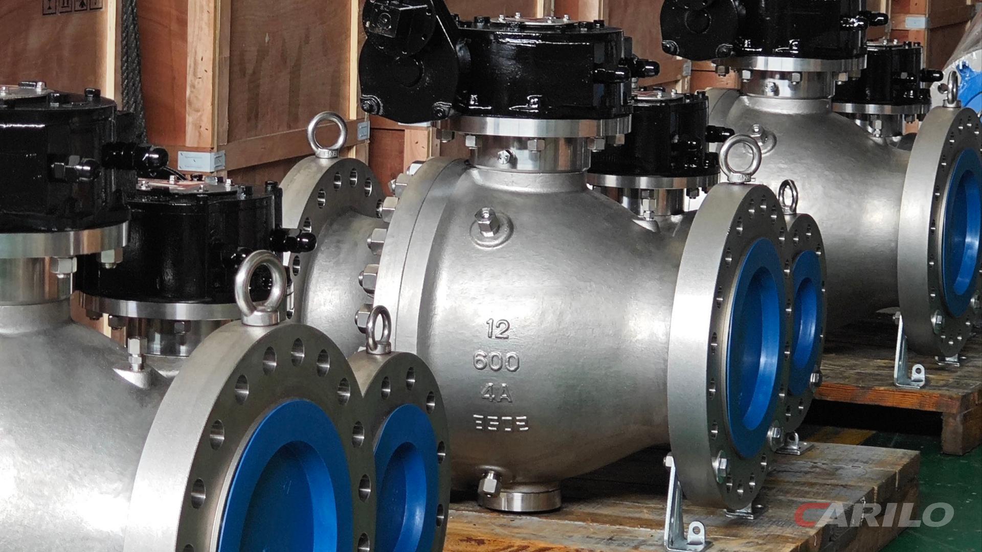
Flanged ball valves in crude oil pipelines must be kept either fully open or fully closed. Throttling at a 45-degree half-open position is strictly prohibited, as it allows impurities to scour and damage internal components.
Routine inspections should be carried out every 3 to 6 months. Cleaning fluid and grease should be injected through the grease fitting to dissolve wax buildup and protect the PTFE sealing rings.
A smooth 90-degree operating motion can significantly extend service life.
Routine Inspection
Flanged ball valves used in crude oil pipelines operate year-round under Class 1500 pressure conditions (25.8 MPa) and are exposed to hydrogen sulfide corrosion above 500 ppm. Routine inspections are performed in accordance with API 598, with a 30-day inspection interval.
Technicians use an ultrasonic thickness gauge to measure valve body wall thickness, with accuracy controlled to within 0.1 mm. A193 B7 flange bolts must be calibrated with a hydraulic torque wrench, and preload must be maintained at 50% of yield strength.
Inspection items include fugitive VOC leakage checks at the stuffing box, with a limit of 100 ppm, as well as stem operating torque tests to quantify the risk of mechanical sticking caused by asphaltene deposits.
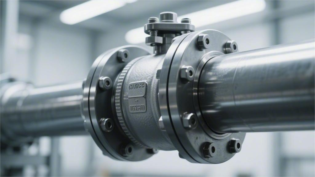
Flange Connection
Seventy percent of external leaks in crude oil pipelines occur at the metal sealing faces on both ends of the valve. Take a vernier caliper and stand beside a Class 1500 pipeline. Look straight along the side. Between the two raised-face (RF) flanges sits a 316L stainless steel spiral wound gasket with an initial thickness of 4.5 mm. Crude oil rushes through the pipe at 3 meters per second, and vibration at the metal faces can reach 50 Hz.
Under normal compression, the gasket thickness should reduce to between 3.2 mm and 3.3 mm. Use a 0.1 mm feeler gauge and check the four symmetrical points around the outer circumference of the flange ring. If the gap difference between any two adjacent measurement points exceeds 0.2 mm, the sealing faces have already shifted out of alignment. Fluid at 25 MPa inside the pipe will be forced outward through that misaligned gap.
On ultra-high-pressure wellhead lines rated Class 2500, the raised-face design is replaced by a ring-type joint (RTJ). A soft iron octagonal ring gasket is seated inside the metal groove. Shine an explosion-proof flashlight along the groove wall. Surface roughness must remain within 63 microinches Ra. A radial scratch deeper than 0.25 mm is enough to let high-pressure crude oil break through the seal and spray out.
These metal components are held together by ASTM A193 B7 high-strength studs and A194 2H heavy hex nuts. Rainwater in the Permian Basin of Texas carries a high salt content, and ambient humidity stays above 80% year-round. Exposed carbon steel studs can develop rust patches within a month. Inspection records must confirm that the metal surface has been coated with blue Xylan fluoropolymer anti-corrosion coating, typically maintained at a thickness of 20 to 30 microns.
Thread rust greatly increases the friction coefficient caused by galling. The hydraulic torque wrench may be set to a pump pressure of 10,000 psi, delivering an apparent torque of 1500 N·m. On paper, the number looks fine, but the actual stud elongation may not even reach 30% of yield strength. In that case, the gasket never receives enough compressive seating stress.
Field engineers in Houston trust physical data from ultrasonic bolt measurement tools more than torque values alone. Place the magnetic probe on the end face of a 2-inch stud and send a high-frequency sound wave through it. The wave travels down the 500 mm bolt, reflects from the bottom, and returns. The display directly shows that the stud has elongated by 0.85 mm. That elongation corresponds exactly to 50% of the material’s yield strength.
Step back and look at the overall external assembly of the fasteners. At least two full threads must be visible outside each nut, with an exposed length of about 5 to 8 mm. Run your hand along the hex edges of the nut. There should be no rounded-off damage from rough pipe wrench use. If one stud shows a difference of more than 15 mm between the exposed lengths on both ends, the load on that assembly is severely unbalanced and the component must be replaced before the next inspection.
Recording flange tightening parameters for different pressure classes is part of routine work. Every inspector carries a material-specific reference chart for verifying the hardware installed on site.
| Pipeline Design Pressure Class | Gasket Type | Required Load-Bearing Bolt Material | Maximum Allowable Misalignment Gap |
|---|---|---|---|
| Class 600 | Spiral Wound Gasket with Inner and Outer Ring (CGI) | A193 B7m (H2S Resistant) | 0.25 mm |
| Class 1500 | Octagonal Metal Ring Gasket (RTJ) | A320 L7 (Low-Temperature Service) | 0.15 mm |
| Class 2500 | Oval Metal Ring Gasket (RTJ) | A193 B16 (High-Temperature Service) | 0.10 mm |
Crude oil flowing at high velocity through the pipeline can generate static electricity. An insulating non-metallic graphite material sits between the two metal flanges. Use a multimeter to measure the resistance of the copper bonding jumper. The reading must never exceed 10 ohms. Once resistance rises above the limit, even a tiny static spark can ignite a surrounding methane-air mixture at a concentration of 4%.
In winter, ambient temperatures in the North Sea oilfields can drop to -20°C, while crude oil inside the pipe remains at 80°C. A 10-meter steel pipe can expand or contract by more than 10 mm under a 100-degree temperature difference. This physical deformation transfers enormous bending stress directly to the flange connections at both ends. Use an infrared thermometer to scan the studs and the flange ring, and record whether the temperature difference between them exceeds 30°C.
Look down along the bottom of the pipeline to the ground. Even a coin-sized patch of dark brown oil on the soil must be photographed and logged immediately on the inspection tablet. Put on nitrile gloves and touch the lower edge beneath the sealing face. If black powder with a strong rotten egg smell sticks to your fingers, it means iron sulfide particles from inside have already begun escaping into the air through micro-leaks.
Stem Packing
The inspector uses a Phx42 photoionization detector, holding the probe 5 mm from the outer edge of the packing gland and scanning it at a constant speed. Under U.S. EPA Method 21, the probe speed must be controlled at 1 inch per second. Move too fast, and the reading will be too low. Move too slowly, and the instrument will draw in too much background methane from the surrounding air. Once the display exceeds 100 ppm, the system records a minor gas release event.
At Pump Station No. 2 in the Texas Permian Basin, a reading of 215 ppm was recorded last week. A maintenance technician brought in a hydraulic torque wrench with a digital display to service the ball valve on this Class 1500 pipeline. The wrench was locked at a setpoint of 45 N·m. The gland nuts were tightened clockwise, and each individual turn was limited to no more than 60 degrees.
As the gland settled downward by 0.5 mm, the flexible graphite rings inside were forced outward under compression. The standard factory density of the graphite rings is 1.6 g/cm³. If the technician overtightens them, density can rise above 1.8 g/cm³. Dry friction between the stem and the packing then increases exponentially.
- Use a roughness tester to scan the stem surface; the reading must not exceed Ra 0.8 μm
- Measure static breakaway torque and compare the peak value with last month’s curve
- Use a thin feeler gauge to check the gap on both sides of the gland; the height difference must stay within 0.15 mm
The pneumatic actuator next to it normally has a rated output torque of 1200 N·m. Once dry friction increases, the actuator response time for opening the valve slows by a full 2.4 seconds. An ultrasonic leak detector placed against the metal housing picks up the sound. A faint 40 kHz vibration means crude oil is still seeping out under pressure.
On offshore platforms in the Gulf of Mexico, some valve stuffing boxes use five rings of V-type PTFE packing. Packing with a 40 mm inner diameter sits under direct summer sunlight. A surface temperature gun can read as high as 85°C on the pipe wall. High temperatures soften PTFE and increase the material’s creep rate by 12%.
The top packing ring becomes 0.3 mm thinner under cold flow. The gland completely loses its elastic support from below. The misaligned inner edge of the gland starts scraping hard against the stem surface. The protective nickel plating on the outer stem is only 25 microns thick. Just a few cycles are enough for the hardened packing edge to cut through it.
Once the base metal is exposed to salt-laden humid air, a thin layer of invisible oxide rust begins to form. Rust particles act like sandpaper, cutting across the surface of newly replaced packing. A high-pressure grease gun is connected to the 1/4 NPT threaded port on the side of the stuffing box. The operator pulls the trigger and injects 2 ounces of synthetic fluorinated grease.
- Check the 316L stainless steel backup ring at the bottom for microscopic cracks
- Estimate the surface coverage ratio of fallen metallic debris
- Measure the compression of the disc spring to confirm it has reached exactly 75% of the design value
Crude oil pressure in the line reaches 15 MPa. NLGI Grade 3 grease is viscous enough to resist backflow and washout from the crude oil. The metal backup ring at the base of the packing is immersed daily in acidic crude containing 300 ppm hydrogen sulfide. At the microscopic level, stress corrosion cracking causes the metal edges to flake.
Fine metal particles as small as 0.05 mm get trapped in the gap between the stem and the packing. When the handwheel turns, they cut a long groove into the surface. The detector reading suddenly jumps to the 1400 ppm alarm threshold. The gland nuts are already bottomed out, with fewer than two threads still visible above the bolts.
Under API 598 inspection procedures, this valve is tagged with a red maintenance label. A pressurized leak-sealing crew arrives carrying a specially designed G-clamp, enclosing the entire outside of the stuffing box. A high-pressure pump injects thermosetting resin into the clamp cavity. After 45 minutes, the resin cures and holds firmly against a 28 MPa line pressure.
During the plant turnaround next month, the old packing will be completely removed. The new packing comes with a carbon fiber reinforcement layer. The installation manual specifies an anti-extrusion mechanical clearance of 0.2 mm. Each ring is inserted and compressed individually using a dedicated hydraulic tool applying 20 MPa of force.
All five packing rings are compressed separately, one by one. This staged compression raises the load on the bottom rings to 70%, keeping VOC leakage as low as 15 ppm. Under the old method, where all five rings were installed first and compressed together, the bottom ring received less than 40% of the load.
- Use a hydraulic extraction tool to remove every fragment of the damaged old packing
- Check the cut positions of the new packing rings; adjacent rings must be staggered by 120 degrees
- Use a laser alignment tool to check stem straightness; if the bend exceeds 0.5 mm, it must be scrapped
API 607 fire testing requires the packing set to include a pure graphite fire barrier layer. During inspection, technicians also run a hand over the external fire insulation cover. If the damaged insulation area exceeds 10 cm², it must be recorded in the maintenance log. Torque readings are far more reliable than human feel.
Quartz sand in North Sea crude can reach Mohs hardness 7. The lower metal anti-extrusion ring must keep all of it out of the sealing zone. The clearance between the anti-extrusion ring and the stem is only 0.08 mm. Once wear enlarges that gap to 0.2 mm, the sand gets in.
The internal structure of the graphite packing is then completely crushed by the sand. Infrared thermal imaging shows that the packing zone is 22°C hotter than surrounding areas. The intense heat from dry friction even distorts the nearby metal lattice. In the control room, a red torque alarm flashes on the screen.
Pipeline & Valve Body
Walk up to the pipeline at an oil sands site in Alberta. Outside air temperature is -30°C. The crude flowing inside is diluted and heated to 60°C. The valve body is wrapped in 50 mm thick polyurethane insulation.
Peel back the lower edge of the aluminum cladding around the insulation. Shine a flashlight inside and look for moisture stains. Chloride-laden de-icing water can penetrate the anti-corrosion primer in as little as three weeks.
Use an ultrasonic thickness gauge to measure the steel shell. The original wall thickness of an ASTM A216 WCB carbon steel valve body is 22.5 mm. Electrochemical corrosion caused by trapped moisture beneath the insulation steadily consumes the outer metal layer.
Apply couplant to the thickness gauge probe and place it on the six fixed inspection points at the bottom of the valve body. Quartz sand and asphaltenes in the crude settle along the lower belly of the valve. When the reading drops to 18.2 mm, mark the spot with a yellow paint marker.
High-sulfur crude imported from the Middle East can contain 1500 ppm hydrogen sulfide. Tiny hydrogen atoms in the acidic fluid diffuse deep into the metal lattice.
- Use phased array ultrasonic equipment to scan a 10 × 10 cm grid on the steel wall
- Watch the color display for internal cracks longer than 5 mm
- Use a portable hardness tester on the weld transition area and keep the reading within 22 HRC
Now look down at the drain port at the very bottom of the main valve body. A 3/4-inch NPT threaded plug is installed there. Months of 50 Hz low-frequency vibration from the line fluid can gradually loosen the threads.
Place a sheet of white industrial filter paper directly under the drain plug and wait 5 minutes. If a single drop of crude seeps out, it will quickly spread into a brown oil ring about 2 cm in diameter.
Take out an explosion-proof bronze wrench from the toolbox and fit it onto the hex head of the vent valve. Try applying 20 N·m of force. If it is seized, stop immediately. Never slip a one-meter extension bar over it and force it open.
The upstream transmission line has an inner diameter of 24 inches. At the valve flange, the flow path suddenly narrows to 20 inches. Crude velocity rises from 2.5 m/s to 3.8 m/s.
Sand particles in the oil hit the valve cavity wall at a 45-degree angle. This high-speed erosion polishes the internal surface until it looks mirror-bright. Thickness records show that this area loses 0.3 mm per year.
Attach the magnetic base of the acoustic emission sensor to the side of the valve body. Normal background flow noise is about 45 dB.
Watch the screen on the portable spectrum analyzer. A sharp 85 dB spike appears in the 20 kHz band. Fluid bubbles are collapsing against the steel wall, and microscopic metal loss is occurring at that exact location.
Take out a dry film thickness gauge and check the external epoxy coating. A newly applied anti-corrosion coating should be between 250 and 300 microns thick. On offshore platforms in the Gulf of Mexico, the air is saturated with salt.
- Set the holiday detector to 2000 volts and scan the coating for pinholes
- If a 1 mm exposed spot is found, record it in the maintenance form
- Use a copper wire brush to remove any lifting paint around the edges
- Touch up a 5 × 5 cm area with a 150-micron zinc-rich primer
Shift your view downward to the steel saddle supporting the 5-ton valve body. A PTFE slide plate sits between the valve body and the saddle, with an original thickness of 10 mm.
Measure the edge of the slide plate with a vernier caliper. If it has worn down to only 4 mm, the entire pipe has already sagged badly. The flange faces at both ends are then carrying a bending shear load of 15,000 lb.
Look for the 316 stainless steel nameplate riveted to the neck of the valve body. Acid rain may have corroded through all four small aluminum rivets. Secure the loose plate temporarily with two stainless steel cable ties.
A row of heat number stamps is marked on the nameplate. Traceability records may lead back to an Italian foundry where the batch was poured in a 50-ton heat. The plate also shows a maximum service temperature of 200°C.
Walk around to the side and inspect the bypass line. A 2-inch branch pipe is welded directly to the main valve body. Under U.S. standard Schedule 160, the wall thickness is 8.7 mm.
Aim the probe at the 90-degree elbow of the bypass line. Fluid impact doubles when the flow changes direction. The measured wall loss rate is 50% faster than that of the main line.
If the thickness gauge reading drops below the danger threshold of 16.5 mm, call the remote control room and request a reduction in pump station output. The pressure gauge should fall from 25 MPa to 15 MPa.
Spray the surface with cleaning solvent to remove dirt deposits. Once the dust falls away, wipe the grease from the thickness measurement point with a cloth so it can be rechecked on the same day next month.
Seal Protection
Untreated crude in pipelines from the Permian Basin in Texas can contain 3% sulfur and often carries 50-micron quartz sand.
Under these conditions, an unprotected PTFE seat may last less than four months.
If 2 ounces of API 6D synthetic hydrocarbon sealant grease are injected every 20 operating cycles, and PEEK sealing rings are used, the leak-free internal service life of an ASME Class 900 flanged ball valve can be extended to more than 36 months.
Grease Injection Metering
At crude gathering stations in the Permian Basin, blindly injecting sealing grease into large-diameter flanged ball valves by feel is a recipe for trouble. The field follows a fixed rule: for a 36-inch ASME Class 600 pipeline valve, 1 ounce of synthetic hydrocarbon sealing grease must be injected for every additional inch of nominal diameter.
For a 36-inch valve, the high-pressure pneumatic grease gun in hand must deliver exactly 36 ounces. That equals two standard 18-ounce refill cartridges. Anything less is not enough to finish the job; anything more is simply waste.
The line continuously carries crude at 1200 psi. To force thick industrial grease into the less-than-2 mm gap between the metal ball and the soft seat, the grease gun pressure must be set to at least 1500 psi.
Clamp the metal hose securely onto the giant button-head fitting on the side of the valve, squeeze the pneumatic trigger, and keep your eyes on the external pressure gauge. The moment the pressure climbs above 3000 psi, release immediately. If you keep forcing grease in, the spring-loaded metal seat ring inside can deform under the excessive external load.
The grease is highly viscous and moves slowly through narrow metal grooves. After every 2 or 3 ounces injected, pause for 5 seconds. Give the grease time to spread and work its way deeper into the sealing path.
- For a 16-inch valve, prepare 16 ounces of sealing grease for one maintenance cycle
- For equipment with two symmetrical grease ports, split the total injection amount evenly between both sides
- Each stroke of a manual hydraulic grease gun delivers an exact 0.05 ounce
- When the temperature drops below 32°F, immediately switch to low-viscosity winter-grade grease
At -20°F on Alaska’s North Slope, grease stored outdoors turns into a hard lump. Before work begins, place the 40-pound grease drum into a portable insulated heater box. Set the thermostat to 100°F and warm it for a full two hours before the grease becomes flowable again.
As it is pushed through a 1/4-inch hose, gauge pressure can easily rise toward 4500 psi. At low temperatures, the internal HNBR O-ring becomes stiff and hard. If resistance is too high and grease will not flow, never force it.
Go to the bottom of the valve and open the drain valve with a large wrench. Drain off 2 or 3 gallons of condensate and trapped water. Once cavity pressure drops, grease at 1800 psi can slide smoothly into the sealing surface with no opposing internal force.
In the Bakken shale fields of North Dakota, crude contains 50-micron quartz sand. These abrasive particles wedge into the edge of PEEK soft seals. To purge them out, the maintenance cycle is shortened sharply to once every 60 days.
Because the maintenance frequency increases, the amount injected each time must be reduced. The operating manual requires only half the original calculated amount. For a 12-inch pipeline block valve serviced every two months, injection stops at 6 ounces.
- During a 60-day high-frequency maintenance cycle, inject only half of the theoretical grease volume each time
- If more than 5 gallons of oily sludge are removed from the bottom of the cavity, the internal chamber must be fully drained and cleaned
- Before using a high-pressure fitting, wipe the giant button-head fitting clean with a dry cloth
- Before removing the hose, open the pressure relief valve on the grease gun to vent all residual pressure in the line
Besides the large fitting at the bottom, large-diameter API 6D ball valves also have a tiny backup grease port at the top. This one is specifically intended for the stem packing box. The gap between the stem and the packing is less than 1 mm.
Here, the amount is not calculated by inches. Switch to a smaller manual grease gun that dispenses 0.1 ounce with each squeeze. Five squeezes inject exactly 0.5 ounce.
Shine a flashlight on the metal flange ring at the top of the stem. Once you see a thin line of fresh, clean grease pushing out a ring of old blackened grease, the job is done. Wipe away any excess grease on the outside with a rag.
Then screw on the threaded dust cap. That way, dried mud and debris outside will not be forced into the sensitive sealing groove together with fresh grease during the next connection.
Solid Deposit Removal
In crude produced from the Bakken shale fields, wax begins to solidify once the temperature drops below 65°F. Yellow-brown wax adheres to the metal ball inside a 24-inch flanged ball valve and has a hardness similar to a household bar of soap. When operators inspect it with a borescope, they often find solid deposits as thick as 0.2 inch on the ball surface.
If the cavity is full of wax and the pneumatic actuator is forced to close the valve anyway, the entire unit may be ruined. A torque of 400,000 in-lb drags the ball, covered with hardened deposits, across the PEEK soft seat. A single operation can cut a physical groove as deep as 0.05 inch into the smooth seat edge.
To deal with wax buildup, experienced crews in the Permian Basin rely on heat tracing. Industrial electric heat tracing cable is tightly wrapped around the outside of an ASME Class 600 valve body, and the temperature controller is set to 140°F. After at least 45 minutes of heating, the wax inside the cavity gradually softens into a thick liquid.
Heat alone is not enough. The 0.02-inch dead-leg residue stuck to the metal ball surface must be handled chemically. Through the giant button-head grease port, operators use a manual pump to inject 3 gallons of specialized cleaning fluid containing xylene. Its strong penetrating ability allows it to enter sealing gaps smaller than 1 mm.
After injection, the valve handle is left in position for 30 minutes. The xylene needs time to dissolve the stubborn wax. Once the soaking period is over, the control room sends a signal to cycle the 24-inch ball valve through three full open-close strokes.
These full-stroke movements allow the ball to carry the dissolved residue into the main flow path, where it is flushed away by crude at 1200 psi. Then the drain valve at the bottom of the valve is opened, and the black waste fluid is collected in a steel container. The solid particles in the drained liquid are usually only 50 microns in diameter and feel like fine sand.
| Production Area & Deposit Type | Microscopic Size & Hardness Characteristics | Physical Damage Pattern | Field Cleaning Criteria |
|---|---|---|---|
| Bakken Shale Wax | Deposit thickness 0.2 inch, soap-like hardness | PEEK seal compressed and deformed by 0.05 inch | Heat trace at 140°F for 45 minutes, inject 3 gallons of xylene cleaning fluid |
| Permian Basin Fracturing Sand | 40–70 mesh, high-hardness quartz | Cuts 0.01-inch scratches into PTFE seat | Drain every 20 days, inject 2 gallons of synthetic flushing oil |
| Gulf of Mexico Barium Sulfate Scale | 150-micron crystals adhered to metal surface | Friction spikes and causes ball seizure | Inject 15% acidic descaling solution during shutdown and soak for 2 hours |
Older Permian pipelines often contain leftover quartz sand from hydraulic fracturing. These coarse 40–70 mesh grains are extremely hard and work their way directly into the edge of PTFE soft seats. Every time the valve opens or closes, the sand acts like sandpaper, leaving white scratches up to 0.01 inch deep on the metal ball surface.
In this case, heating is useless. The field solution is to aggressively increase drain frequency, changing the manual’s half-year interval to a forced drain every 20 days. Operators use two 36-inch pipe wrenches to hold the bottom drain flange, open the drain valve, and release the sand-water mixture accumulated in the cavity.
The discharged slurry is collected in a 5-gallon white plastic bucket. After 30 minutes of settling, as much as 2 inches of pure quartz sand can accumulate at the bottom. To flush out loose sand trapped in the sealing gap, 2 gallons of synthetic flushing oil must be injected through the grease port. This oil has only one-tenth the viscosity of standard sealing grease.
The low-viscosity flushing oil moves quickly through the gap and can carry fine sand out of a 1 mm sealing space. While injecting flushing oil, pressure on the gauge must never exceed 2000 psi. If pressure is too high, the thin oil will simply leak through the worn gap into the main crude line and fail to flush the debris effectively.
Subsea pipelines in the Gulf of Mexico often develop barium sulfate scale. These 150-micron crystalline deposits adhere tightly to the inner wall of carbon steel ball valves, and ordinary solvents cannot remove them. Once the line is shut in, workers put on Level C chemical protective gear and use an acid-resistant pneumatic pump to inject 15% acidic descaling solution into the valve cavity.
After injection, the acid must remain inside for a full 2 hours. As it reacts with the barium sulfate, large volumes of gas are generated and the cavity pressure slowly rises from zero to 300 psi. Personnel must watch the cavity pressure gauge continuously. If it exceeds 400 psi, the upper vent valve must be cracked open slightly to release gas.
During venting, the sharp smell of hydrogen sulfide escapes from the outlet, and the portable four-gas detector sounds continuously. After the 2-hour soak is complete, 150 psi high-pressure steam is blown backward through the drain line to remove the dissolved scale fragments into a temporary waste recovery tank.
Whether wax has been cleaned with xylene or scale has been dissolved with acid, the inside of the valve cavity is left as dry as rusted metal afterward. The original protective oil film is completely stripped away by the chemicals. Immediately afterward, inject a full charge of high-viscosity base oil sealing grease into the 36-inch ball valve—exactly 36 ounces.
The new grease fills the voids left behind by cleaning and fully coats any stubborn remaining sand particles hidden in corners. A fresh 0.1 mm lubrication film is restored between the metal ball and the soft seal. When crude at 1200 psi passes through again, the soft sealing ring can withstand the pressure impact with proper support.
Preventing High Pressure & Deformation
In summer, temperatures in the Permian Basin of Texas can easily reach 110°F. A 24-inch ASME Class 600 ball valve mounted outdoors on the pipeline can reach an external shell temperature of 145°F under direct sunlight. When the valve is fully closed, a large cavity inside traps a full volume of crude oil. As the oil heats up and has nowhere to expand, pressure rises rapidly inside the sealed cavity.
When the valve first closes in the morning, cavity pressure is the same as line pressure at 1200 psi. By 2:00 p.m., the trapped pressure in the cavity can climb to 3200 psi.
Once the abnormal pressure exceeds 3000 psi, the two-ton metal ball is forced hard against the downstream PTFE soft seat.
The yield limit of PTFE is around 2500 psi. Under a load of 3200 psi, a 0.25-inch white sealing ring is flattened like a pancake. When ambient temperature drops back to 70°F at night and pressure falls, that deformed Teflon ring does not spring back. The sealing surface is left with a permanent 0.05-inch indentation.
The next time 1200 psi crude flows through the line, leakage pours straight through that damaged area. To prevent pressure buildup, field-procured valves are required to be fitted with self-relieving seats. Once cavity pressure rises 150 psi above main line pressure, the spring on the upstream side is forced open by a 0.02-inch gap. Less than 8 ounces of crude—about half a mug—are released, and cavity pressure instantly returns to the safe 1200 psi level.
Using a ball valve as a control valve in the operations room is simply a fast way to destroy equipment worth hundreds of thousands of dollars. A ball valve is designed for only two positions: fully open or fully closed. Leave a 16-inch valve at 40% open, and 1200 psi crude is forced through the narrow gap between the ball and the seat. Flow meter readings show that velocity in that gap can surge from a normal 8 ft/s to more than 65 ft/s.
Veteran workers at the Cushing storage terminal in Oklahoma learned this the hard way. Crude carrying 50-micron quartz sand scoured the valve at 65 ft/s for just 3 hours. The abrasive particles, carried by the high-velocity fluid, cut across the PEEK soft seat edge like an industrial water jet.
- The 0.15-inch sealing lip is completely cut away in a full ring
- The metal ball surface is left covered with pits as deep as 0.01 inch
- The noise monitor at the downstream flange records a high-pitched whistle of 110 dB
Once the sealing ring is cut, it becomes useless. Even if actuator output torque is increased to 500,000 in-lb and the ball is forced into the fully closed position, the ultrasonic leak detector still picks up the hiss of internal leakage. As much as 2 gallons of crude leak through every minute. The line cannot be isolated, and downstream filter replacement work must be shut down immediately.
An oversized exhaust valve port on the pneumatic actuator can cause just as much trouble. Moving a 30-inch ball must be deliberately slow. API 6D gives a strict formula: each inch of valve diameter corresponds to 1 second of operating time. For a 30-inch valve, the travel time from fully open to fully closed must never be less than 30 seconds.
Some inexperienced operators over-adjust the pneumatic control panel and open the exhaust port fully, causing a 30-inch valve to slam shut in just 8 seconds. At that moment, 80 gallons of crude per second flowing at 1440 psi are stopped abruptly. The tremendous inertia of the fluid crashes into the metal ball.
The pressure sensor captures an instantaneous impact wave of 4500 psi, which travels back through the line and can be felt as a faint ground tremor even two miles away.
This destructive force strikes the inside of the valve. The rubber O-ring that was originally seated in the metal groove is forced out of place. The FKM fluoroelastomer ring is stretched to 1.5 times its normal length and then swept into the main pipeline like a snapped rubber band. Without the support of the backing spring, the soft seal fails completely during the next pressure test.
Opening a valve against a large differential pressure damages equipment just as quickly. The upstream side is holding 1500 psi, while the downstream side has already been vented for maintenance and sits at 15 psi atmospheric pressure. The full 1485 psi differential presses hard against the ball. The enormous load is concentrated on the downstream nylon seat.
When the ball is forced to turn under these conditions, mechanical friction between the metal ball surface and the nylon seat becomes more than five times higher than normal. The actuator runs at full load, and the ammeter needle shoots into the red. The moment the ball starts to move, the edge of the soft seal is torn by the violent force. A 0.5-inch piece is ripped out of the high-hardness nylon seat.
On large-diameter equipment, there is always a connected 2-inch bypass line. Before operation, that small line must be opened first, allowing crude to hiss downstream. The operator watches the pressure gauges on both sides closely. With the upstream side at 1500 psi and the downstream side gradually rising to 1450 psi, the main valve may only be operated once the pressure difference has dropped below 50 psi.
Operating Practice
API 6D states that using a ball valve for throttling in crude oil service can produce 1.5 mm of linear wear on a PTFE seat within 48 hours.
The handwheel should be operated at a speed of 15 to 20 degrees per second. If the flow velocity exceeds 4.5 m/s, water hammer may occur, and the instantaneous pressure peak can easily exceed the approximately 10 MPa pressure limit of an ASME Class 600 flange.
When crude oil sand content reaches 0.5%, the valve cavity must be flushed and cleared of asphaltenes every 500 operating cycles.
Throttling & Wear Control
API 6D strictly prohibits leaving a ball valve in any half-open position between 10 degrees and 80 degrees. In Bakken crude containing 0.3% quartz sand, once the valve is only half open, the oil is forced through a narrow crescent-shaped gap. Flow velocity instantly surges to 35 m/s, effectively turning the stream into a high-pressure cutting jet.
This sand-laden jet cuts directly into the PTFE soft seat. Under 10 MPa line pressure, it can erode a groove 1.2 mm deep into the sealing ring in just 48 hours. Once more than 0.5 mm of the sealing ring has been worn away, the valve can no longer shut off tightly.
To verify whether the valve has really reached a full-end position, field operators follow several steps:
- Watch the indicator on top of the pneumatic actuator. It must sit exactly against the 0-degree or 90-degree mechanical stop, with no deviation.
- Use a handheld ultrasonic device set to 35–45 kHz and place it against the valve body. A high-frequency hissing sound indicates internal leakage.
- Use an infrared thermometer to scan the downstream pipe. If it is suddenly 3 to 5 degrees cooler than the upstream side, oil is escaping through a gap.
Some people assume that switching to a metal-seated ball valve with an extremely hard tungsten carbide coating of HRC 70 means it can safely run half open. In reality, even metal cannot withstand it. As fluid passes through the narrow gap, the pressure drops sharply and large numbers of tiny bubbles form. When those bubbles collapse downstream, they strike with impacts of 400 MPa, and after 7 days even stainless steel can be pitted into a honeycomb pattern.
On offshore platforms in the North Sea, crude often contains 15% water, and Devlon-modified nylon is commonly used for valve seats. A half-open valve generates intense frictional heat. Once the local temperature exceeds 135°C, the nylon softens. The softened plastic deforms under high pressure and sticks tightly to the metal ball. The next time the valve is closed, the seat tears apart and fails completely.
If the sealing surface has already been damaged by erosion, field crews use the following emergency measures:
- Inject a dense sealing grease mixed with PTFE particles through the grease port to force-seal scratches smaller than 1 mm
- Increase the actuator air supply pressure by 10% so the ball is pressed harder against the damaged seat
- Scan the valve body shell with a thickness gauge to ensure the metal wall has not worn too thin; it must never fall below the 2.5 mm safety limit
When the pipeline is running a pigging operation, the ball valve must not be even slightly misaligned. If a 300 mm pig traveling at 2.5 m/s strikes a ball that is not fully open, the blocked crude behind it can build up to 8 MPa in just 3 seconds.
Tons of thrust will drive the pig, together with hardened asphaltic debris in the line, straight into the spring gap behind the valve seat. The disc spring becomes completely jammed with sand and sludge, the seat can no longer rebound, and the entire flanged ball valve must be removed and discarded.
Torque & Opening/Closing
At winter wellsites in Alberta, Canada, temperatures fall below -30°C, and API 12 heavy crude becomes a thick semi-solid mass. If the ball remains stationary in the pipeline for more than 72 hours, a wax shell up to 3 mm thick can form on its surface.
This hard shell bonds the metal ball tightly to the PEEK seat. Under normal conditions, the breakaway torque for an NPS 16 Class 600 ball valve is about 8,500 N·m. Under this low-temperature wax-freeze condition, the torque reading can surge above 19,000 N·m.
If an inspector slips a 2-meter cheater bar over the handwheel and pulls hard, the entire mechanical load is concentrated at the shear section of the stem. A standard 17-4PH precipitation-hardened stainless steel stem has a yield strength of about 450 MPa. Once the force exceeds the physical limit, the stem can twist off internally below the stuffing box.
From the outside, the handwheel may appear to have turned three full revolutions, while the internal ball has not moved even 1 degree. In gathering stations across the Permian Basin, pneumatic scotch yoke actuators are often paired with high-pressure air receivers to handle the sharp torque rise caused by high-viscosity crude.
The operator increases instrument air pressure from the normal 80 psi to 120 psi. At the start of the stroke, the scotch yoke uses mechanical leverage to boost output torque by 1.5 times. With a dull metallic grinding sound, the ball crushes the wax deposits and breaks free from static lockup.
Forcing open a high-pressure valve can easily damage the equipment. Standard operating procedure requires opening the bypass line first. A 2-inch bypass line is used to introduce upstream crude at 8 MPa to the downstream side for 5 minutes in advance. Once the differential pressure across the ball valve drops below 0.5 MPa, the operator may then turn the handwheel using the calibrated torque.
Hydraulic lock can drive the torque gauge off the scale. Residual liquid crude trapped in the closed center cavity is heated by the Texas sun during the day. For every 1°C rise in temperature, cavity pressure can jump by about 1 MPa. Turning the handwheel under these conditions is equivalent to fighting an internal hydraulic pressure of up to 30 MPa.
To release hydraulic lock, use the pressure relief drain at the bottom of the valve body. Open the NPT 1/2-inch vent plug with a wrench and drain off half a gallon of crude. Once cavity pressure falls to the same level as the line, check the torque indicator on the gearbox. The pointer should return to the green safe zone.
For long-distance crude lines above 20 inches in diameter, daily throughput reaches hundreds of thousands of barrels. The mass of liquid is enormous and essentially incompressible. If fully flowing crude strikes a closing ball in less than 5 seconds, all of that kinetic energy is converted into destructive static pressure.
At a line velocity of 3.2 m/s, the original 10 MPa pipeline pressure can spike into a 28 MPa water hammer surge. The shock wave travels backward through the steel pipe at 1000 m/s, heavily damaging every flange connection along the way.
An ASME Class 300 flange joint cannot withstand such instantaneous extreme pressure. Eight high-strength M36 flange bolts can be stretched by 0.2 mm, the fire-safe spiral wound gasket can rupture immediately, and crude oil can jet out like a fountain more than ten meters away.
API 6D specifies mandatory minimum opening and closing times. When adjusting the actuator exhaust throttling valve on site, maintenance personnel use a stopwatch while watching the travel indicator, strictly controlling the ball rotation speed.
| Flanged Ball Valve Size (NPS) | Pipeline Flow Velocity Standard | Required Safe Opening/Closing Time | Actuator Exhaust Orifice Size |
|---|---|---|---|
| 12 | Less than 2.5 m/s | 35 to 50 seconds | 1/4 inch |
| 16 | Less than 2.0 m/s | 55 to 70 seconds | 3/8 inch |
| 24 | Less than 1.8 m/s | 90 to 120 seconds | 1/2 inch |
| 36 | Less than 1.5 m/s | 150 to 200 seconds | 3/4 inch |
Manual gearboxes used on large-diameter ball valves are often set to a reduction ratio of 250:1 or even higher. The operator must turn the handwheel 250 times to rotate the stem through 90 degrees. This worm gear system magnifies human force by several hundred times, but at the same time it physically slows the action, mechanically enforcing the safe operating speed needed to prevent water hammer.
When the emergency shutdown (ESD) system is triggered, the ball valve must achieve full shutdown within 10 seconds. The bidirectional solenoid valve on the cylinder de-energizes instantly, and high-pressure gas is vented aggressively to atmosphere through a 1-inch quick exhaust valve. At that moment, water hammer prevention becomes secondary. Cutting off the fuel source to a fire scene becomes the only priority.
This rapid closure applies a torsional shock 200% above rated load at the stem connection. After any real ESD event, ultrasonic inspection must be performed across the stem spline and the ball keyway. If a metal microcrack larger than 0.1 mm is detected, the entire internal assembly must be scrapped.
Before routine opening and closing, the seat grease injection record must be checked. Fifteen minutes before starting the actuator, use a pneumatic grease gun to inject 3 pounds of fully synthetic valve grease into the ring groove behind the seat. This oil film reduces the dynamic friction coefficient at the ball surface from 0.15 to 0.04.
With friction reduced, operating torque drops smoothly from 12,000 N·m to 8,500 N·m. Wear on the worm gear inside the gearbox is greatly reduced. If lithium-based grease is added to the bronze bearings inside the actuator housing every six months, this flanged ball valve can survive its full 15-year design life even in windblown sand conditions.
Pressure Relief & Drainage
As crude oil flows through a flanged ball valve, high-pressure media inevitably accumulate in the large center cavity. Once the PEEK seat rings at both ends are fully sealed, as much as 45 liters of Saudi heavy crude can be trapped inside the cast steel body.
In the Rub’ al Khali desert of the Middle East, afternoon temperatures regularly exceed 55°C. The carbon steel valve body absorbs heat aggressively under direct sunlight, and the liquid inside the sealed cavity expands dramatically. Monitoring data show that for every 1°C rise in temperature, cavity pressure increases by about 1.1 MPa.
API 6D requires that equipment be fitted with an automatic pressure relief system. Once cavity pressure exceeds 1.33 times the rated working pressure of the pipeline, the internal spring must lift and discharge the trapped fluid to the low-pressure side of the system.
Many older ASME Class 900 ball valves in service do not have this self-relieving mechanism. Personnel must use explosion-proof tools and manually crack open the NPT 1/2-inch vent plug on the back of the valve body. Loosen it by only half a turn. As high-pressure gas whistles through the threads, the operator must stop and wait.
Blindly removing the vent plug completely can cause severe injury or death. Residual pressure as high as 15 MPa can turn that 200-gram metal plug into a bullet, punching through the sheet-metal wall of a control room 30 meters away. The pressure must be released slowly while the operator watches the gauge until it falls back into the safe zone around 0.5 MPa.
Undehydrated crude contains formation water mixed with high concentrations of hydrogen sulfide (H2S). If the oil-gas mixture sits in the valve cavity for more than 24 hours, water separates by gravity and collects around the drain valve at the very bottom of the body.
- Personnel must wear positive-pressure SCBA, with a portable gas detector clipped 10 cm from the chest
- If the H2S reading exceeds the 10 ppm alarm threshold, the detector will trigger high-frequency sound and vibration alarms
- A stainless steel corrugated hose rated for 20 MPa must connect the drain outlet securely to the closed drain system
Blizzard conditions in North Dakota can drive nighttime temperatures down to -40°C. Free water trapped at the bottom of the cavity freezes into solid ice and expands in volume by 9%. This physical expansion can generate as much as 200 MPa of force, tearing a 15 cm crack into a 45 mm thick A350 LF2 low-temperature carbon steel valve body.
For that reason, pre-winter drainage becomes a mandatory task at wellsites. Maintenance staff open the 3/4-inch bottom drain ball valve, and the first discharge is usually a dark brown mixture of sludge and water. Quartz sand particles mixed in the flow strike the bottom of the transparent sample glass bottle with a clear rattling sound.
The draining process usually lasts 3 to 5 minutes. Once the discharge turns into pure yellow-green crude with a sharp odor and the fine gas bubbles stop appearing, the bottom water and solid contaminants have been completely removed.
Drainage prevents freeze expansion in the line and also removes asphaltene deposits hidden in dead zones. When BS&W approaches 3%, sticky asphaltenes can fill the disc spring chamber. The spring then loses its 5000 N seat-loading force, and the PTFE sealing ring can no longer press tightly against the stainless steel ball.
Simply opening the bottom drain is not enough to remove stubborn deposits. Inspection crews bring over a 60 kg pneumatic grease pump. A high-pressure hose is connected to the dedicated cavity injection port, and with the rhythmic pounding of the air pump, 15 gallons of industrial valve cleaning fluid are forced into the inside of the valve.
The high-xylene cleaning solution penetrates every narrow metal gap. After soaking for a full 45 minutes, the hard asphaltene deposits soften into a flowing paste. The operator then reopens the bottom drain valve, and the liquefied black sludge flows through the 2-inch drain line into the waste recovery tank.
Frequent drain operations can quickly wear out the small auxiliary drain valve itself. Crude from Canada’s oil sands contains large quantities of extremely hard silicate particles. If the valve is drained four times a month, the metal ball inside the drain valve can be scarred with dense grooves as deep as 0.5 mm in less than six months.
- If crude begins dripping from the drain outlet, the operator must never force the short handle with brute strength
- Applying more than the 80 N·m torque limit will only twist off the 12 mm stem
- Depressurize the upstream line to zero and replace the worn drain valve with a new unit made of Super Duplex stainless steel
Tightening the drain valve and vent plug is governed by a strict procedure. The operator takes out a digital torque wrench from the belt, coats the metal threads with an anti-seize compound containing more than 15% copper, aligns the threads, and tightens slowly to the specified 65 N·m torque listed in the maintenance manual.
This lubricant effectively prevents chemical corrosion caused by high-sulfur crude. When hydrogen sulfide contacts condensed water, it forms highly corrosive hydrosulfuric acid. If carbon steel threads are assembled in such harsh conditions, severe electrochemical reaction can occur in less than three months, causing the mating threads to seize and weld together through galling.
On flanged ball valves with double block and bleed (DBB) construction, pressure relief and drainage provide a direct test of seal integrity. If both sides of the line remain at 12 MPa and the ball valve is fully closed with healthy seals, then after the cavity pressure is vented to zero, the drain outlet should not leak a single drop of oil.
If the drain outlet leaks crude at a rate above 150 mL per minute, field personnel mark the maintenance record under “upstream soft seat cut damage.” On the same day, the engineer uses the online leak report to requisition a new set of fully synthetic HNBR sealing components from the warehouse for replacement during maintenance.

")