
DBB compact manifolds are critical isolation equipment in oil, gas, and petrochemical applications. In Class 600-900 service, seal failures cause costly unplanned shutdowns — proper maintenance cuts this risk by up to 80%.

Replacing Valve Seals
Checking Seal Damage
DBB valve seat seal damage does not occur suddenly; in most cases, the sealing surface has given multiple warning signals before leakage occurs. The first step in checking for seal damage is to determine the current state of the seal and then decide whether a shutdown for maintenance is necessary. Visual inspection is the most direct method. Using a flashlight to closely examine the valve seat sealing surface, a normal elastic seal (made of materials such as EPDM, fluoroelastomer, or polytetrafluoroethylene) should appear intact, continuous, and free of cracks. If a fine network of cracks is observed on the surface, or if there are noticeable gaps or tears on the sealing lip, it indicates that the seal has entered a stage of physical damage, which is irreversible and requires replacement.
In 2023, during a routine inspection at a chemical plant’s hydrocracking unit, an operator found a visible 0.3mm crack on the upstream side of the DBB valve’s sealing surface. Due to the timely replacement, an unplanned shutdown caused by high-pressure hydrogen leakage was avoided [1](https://www.emerson.com/us-en/automation/control-valves/double-block-bleed-valve-manifold). Discoloration of the seal surface is also an important warning sign. EPDM material will turn from black to brown and harden under continuous high-temperature conditions (above 130°C); fluoroelastomer will become shiny and sticky after long-term contact with mineral oil. These are typical signs of material aging.
The aging of polytetrafluoroethylene seals is manifested by whitening of the surface, the appearance of fine cracks, and increased hardness, leading to a decrease in sealing performance. A petrochemical company recorded the average service life of valve seat seals against operating temperature: for every 10°C increase in operating temperature, the seal life is shortened by approximately 30%—this data comes from the company’s equipment archives from 2019 to 2023. The hardness change of elastic seals can be judged by touch. Using a fingernail to gently press the sealing lip, a normal seal feels soft and elastic, and the fingernail impression will quickly rebound to its original shape.
If a noticeable indentation remains after pressing and does not rebound, it indicates that the elasticity has severely decreased, and even if it is not leaking currently, it is on the verge of leaking. This tactile test is very practical for on-site valve inspection without disassembly and does not require any instruments. The inspection of metal sealing surfaces (hard seats) is different from that of elastic seals, mainly focusing on the integrity of the sealing line (seat bore sealing contact line). Using an endoscope to look into the valve body, check whether the sealing line is continuous, and whether there are any signs of erosion, corrosion pits, or foreign object indentation marks.
The sealing line width of a DBB valve is usually only 0.5-1.5mm, and any local interruption of the sealing line means a potential internal leakage hazard. In 2022, an endoscope inspection at a natural gas pipeline station found sand particle indentation marks on the DBB valve’s sealing line. After removing the foreign objects and retesting, the leakage rate returned to an acceptable range [2](https://www.swagelok.com/fluid-system-tips/signs-of-valve-leakage). During the inspection, do not overlook the connection sealing surfaces between the valve body and the pipeline.
The flange sealing surfaces at both ends of the DBB valve (usually using spiral-wound gaskets or ring gaskets) are the second line of defense against internal leakage. If there are crushing marks on the flange sealing surfaces, gasket extrusion, or if the fastening bolts feel loose (tested by gently tapping with a torque wrench), it indicates that the sealing surfaces have been damaged. In this case, simply replacing the valve seal will not solve the problem; the flange sealing surfaces must also be addressed. The second type of signal for seal damage is functional abnormality—even if no physical damage is seen, changes in valve operating parameters can reveal a trend of deteriorating seal condition.
During normal operation of a DBB valve, if the upstream pressure is stable but the downstream pressure shows a slow rise (even if the increase is very small, such as 0.1-0.2 bar), it is often a sign that the valve seat sealing surface has begun to leak internally. This pressure drift is the most difficult to detect in the early stages because the change is slow and can easily be overlooked by operators during routine inspections. It is recommended to install a pressure gauge with an accuracy of no less than 0.5 on both the upstream and downstream sides of the DBB valve, so that pressure changes at the 0.01 bar level can be read. The phase state and pressure level of the leaking medium determine the frequency and focus of the damage inspection.
For volatile media (such as light hydrocarbons, liquefied petroleum gas), there may be no obvious dripping after the valve seat seal is damaged during normal operation, but the smell can be detected—this is an effective low-cost detection method. The API 624 standard requires that all DBB valves used in flammable or hazardous media must undergo a factory helium mass spectrometer leak test, with a qualified standard of a leakage rate not exceeding 50 ppmv [3](https://www.api.org/products-and-services/standards). During on-site inspections, if you have an olfactory detector or a portable combustible gas detector on hand, you can first use it to scan the outside of the valve body for any trace gas leakage before deciding whether to disassemble for inspection. The chemical compatibility of the medium is also an accelerating factor for seal damage.
The same EPDM seal can be used for 5 years in a water system, but it may swell and fail within 3 months in a solvent with a high aromatic content. In chemical plants, it is recommended that maintenance personnel establish a compatibility list of seals and operating media, and mark the maximum allowable concentration. In a polyester plant, the DBB valve’s EPDM seal failed completely within 2 weeks after the raw material was changed (increasing the proportion of ethylene glycol), and the problem was solved by switching to fluoroelastomer material. This case illustrates that seal damage does not necessarily come from physical wear; chemical corrosion can also quickly destroy sealing performance.
The frequency of inspection needs to be determined by considering the valve diameter, operating pressure, and medium characteristics. For large-diameter (DN50 and above) high-pressure (Class 600 and above) DBB valves, it is recommended to conduct a seal condition assessment every 6 months; for small-diameter low-pressure valves, the interval can be extended to 12-18 months. For systems where the medium contains solid particles or is prone to scaling, the inspection cycle should be shortened by 50%, because the abrasive particles formed on the sealing surface will accelerate wear. After the inspection cycle of the DBB valve in the gasification unit of a coal chemical company was shortened from 12 months to 6 months, the unexpected failure rate of the seal was reduced from 15% to less than 4%.
The last type of damage mode is installation damage—seals are cut, excessively squeezed, or installed in the wrong direction during the assembly process. If such problems are not found during the initial commissioning, the seal will suddenly fail within a few hours to days of operation. If a sharp cut mark is found on the sealing lip during the inspection (different from corrosion cracks, it is a neat cut), it can basically be determined as installation damage, not aging or chemical corrosion. This situation is especially common during re-installation after maintenance, often because the operator did not use the correct installation tool (a special seal installation guide sleeve should be used), and directly pried it in with a screwdriver.
Required Tools List
The tools needed for replacing DBB valve seat seals can be divided into essential tools and auxiliary tools. Essential tools are those without which the job cannot be completed, while auxiliary tools make the job safer and more efficient. It is much more time-saving to prepare all the tools before starting than to stop midway to look for them.
| Tool Name | Specification Requirements | Purpose Description |
|---|---|---|
| Torque Wrench | Range covering valve seat bolt torque values (typically M8-M16 bolts torque 30-150Nm, Class 150-600 valves) | The valve seat sealing surface bolts must be tightened to the specified torque, and a torque deviation exceeding ±10% will cause uneven force on the sealing surface, leading to leakage |
| Torque Wrench Calibration Certificate | Third-party calibration report with valid period, calibration accuracy ≤±2% | If the on-site torque wrench does not have a calibration certificate, the actual measured torque may deviate from the dial reading by more than 20%, rendering it completely meaningless |
| O-ring Removal Tool (Plastic Guide Fork) | Non-metallic material to prevent scratching the valve seat groove surface; size matching the O-ring inner diameter | Using a metal tool to remove the O-ring will scratch the groove, causing the new seal to leak even after installation |
| New O-ring/Valve Seat Seal | Material must match the operating medium and temperature (EPDM/fluororubber/PTFE/graphite filled, etc.); 2 sets of new parts of the same specification | The most common cause of premature seal failure is incorrect spare part material; 2 sets of the same specification are because the installation process may damage the first set |
| Lint-free Cleaning Cloth (Medical-grade Non-woven Fabric or Industrial Dust-free Paper) | Particle size residue complies with ISO Class 5 (Class 100) cleanliness standard | Regular cloth sheds fibers that stick to the sealing surface and become abrasive particles; particle residue in the valve seat sealing surface groove will cause the new seal lip to be scratched |
| Seal Compatible Lubricant | Chemically compatible with seal material and medium (food-grade silicone grease/perfluoropolyether lubricant/medium itself) | EPDM seals must not use petroleum-based lubricants (causes swelling); oil-based lubricants are prohibited in oxygen systems due to explosion risk |
| Hex Key Set or Socket Set | M5-M14 hex keys or 12.7mm (1/2 inch) drive sockets, made of S2 alloy steel or chrome vanadium steel | DBB valve cover bolts are usually hex or external hex structures, need to be confirmed according to the valve body model |
| Soft Metal Sleeve (Copper or Aluminum Sheet) | Thickness 0.5-1mm, cut to match the shape of the wrench mouth | When applying force to the valve body with a wrench, a soft metal must be used to pad the valve body surface to prevent the valve body surface coating or coating from being scratched by metal |
| Compressed Air (Dry) or Nitrogen | Dew point -40°C or below, oil content ≤0.1mg/m³ | After cleaning the valve seat groove and sealing surface, use dry gas to purge, confirming no residual foreign matter and moisture |
| Pressure Gauge or Digital Pressure Sensor | Range 150% of test pressure (e.g., for test pressure 10bar, select 15bar range); accuracy level 0.5 or above | Monitor pressure changes during pressurization and pressure holding to determine the sealing status |
| Anti-static Flame-retardant Gloves | Comply with EN 388 standard, anti-static and flame-retardant | The valve seat sealing surface is a precision smooth surface, and the grease and skin debris on the hands will cause local corrosion |
The above is the complete tool list for DBB valve seat seal replacement. In actual operations, it is necessary to refer to the maintenance manual of the specific valve brand and model to confirm if there are any special tool requirements. Some imported brands (such as Fisher, Emerson, Metso) have special seal installation guide sleeves for their DBB valves. Without this guide sleeve, it is very easy to install the seal lip in the wrong direction or scratch it by hand.
Having the tools ready is just the first step; the quality and condition of the tools themselves directly determine the success or failure of the operation. I have seen too many cases where the seal was replaced but leaked again within a week, and the root cause was not the quality issue of the seal itself, but the improper condition of the tools. The following checkpoints must be confirmed before each operation.
The biggest problem with torque wrenches is not the lack of calibration, but the preheating before use. A torque wrench is a precision instrument. If taken directly from the toolbox and used, the reading may have a deviation of 5%-10%. The correct procedure is to first make the torque wrench turn freely 3-5 times to let the internal spring mechanism preheat to the working temperature before starting the formal tightening. This preheating process is particularly important in cold weather (below 10°C). When I was doing DBB valve maintenance at a natural gas station in Inner Mongolia, I always warmed the wrench in my hands for 5 minutes before using it in winter outdoor operations—this is a trick taught by a veteran worker. Later, when I bought a digital torque wrench, I found that the preheating by hand temperature and the preheating reading of the digital wrench were consistent in the direction of deviation.
The O-ring groove cleaning tool is more important than the O-ring itself. Many people focus on the quality of the new seal but ignore the condition of the groove. After the old O-ring is removed, there are often indentations of the seal on the bottom and sides of the groove, and there may be oxide scales or corrosion products on the groove walls. Using a cotton swab dipped in anhydrous alcohol can clean the bottom of the groove, but the corrosion layer on the side walls needs to be gently removed with a plastic hard-bristled brush—do not scrape hard, otherwise it will destroy the dimensional accuracy of the groove. If the groove itself is damaged (scratches deeper than 0.1mm, or the groove width has expanded), replacing the seal alone cannot solve the problem, and the valve seat needs to be repaired or even the entire valve seat assembly needs to be replaced.
The wrong choice of lubricant is the main cause of chemical seal failure. DBB valves are used in different medium systems, and the choice of lubricant is completely different: natural gas systems can only use instrument-grade helium or special natural gas valve seat lubricant, oxygen systems must use fluorinated lubricant or no lubricant at all, and hydrogen systems need to pay attention to the hydrogen permeability compatibility of the lubricant with the seal. The consequence of each wrong lubricant is immediate—the petroleum-based lubricant will cause the EPDM seal to swell by more than 30% in volume within 2 hours, directly losing its sealing ability [4](https://www.parker.com/Shop/Technical-Papers/Chemical-Compatibility-of-Elastomers).
A tool often overlooked on site is the seal installation guide sleeve (seal installation sleeve). The cost of this small accessory may be only a few dollars, but it can increase the first-time installation success rate of the seal from 70% to nearly 100%. The role of the guide sleeve is to keep the lip of the seal in the correct direction when it is introduced into the groove. Without the guide sleeve, when using a screwdriver to guide the seal, the probability of the lip turning over is very high. Once the seal is turned over, even if it is barely installed into the groove, the sealing performance will be reduced by more than 50%. Almost all seal manufacturers (Parker, Greene Tweed, James Walker) provide installation guide sleeves that match their own seals.
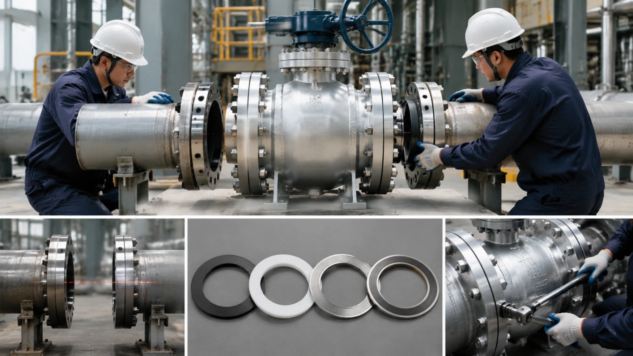
New Seal Installation
The installation of new seals is the most critical step in the entire DBB valve maintenance process. The quality of the installation directly determines whether the valve can operate normally in the future. All installation operations must be performed after the valve body has been completely depressurized, isolated, and emptied. Any operation under pressure will cause misalignment in the seal installation, and in severe cases, it can directly lead to seal damage or personal injury.
- Preparation of the working surface for cleaning and confirmation. After cleaning the valve seat groove with anhydrous alcohol, use dry compressed air to blow it out, ensuring that there are no foreign objects, grease, or moisture residues at the bottom and sidewalls of the groove. Use an endoscope to confirm again that there are no scratches, corrosion pits, or deformations on the groove surface. If the groove dimensions exceed the drawing tolerances (typically width tolerance ±0.05mm, depth tolerance ±0.02mm), the operation must be paused, and the valve manufacturer or a professional repair service must be contacted for handling.
- Visual inspection and dimensional verification of the new seal. Before taking out the new seal, hands must be covered with anti-static and flame-retardant gloves. First, visually and manually confirm that the seal has no cracks, no deformation, and that the material is consistent with the original specifications. Use calipers to measure the inner diameter, outer diameter, and cross-sectional diameter of the seal, and compare them with the old part or the manufacturer’s specifications. The cross-sectional diameter tolerance of the DBB valve seat seal is usually within ±0.05mm. Seals that exceed this tolerance will lead to insufficient or excessive compression.
- Seal lubrication. Apply a very thin layer of compatible lubricant to the lip and outer circumference of the seal. The purpose of the lubricant is to assist in the smooth installation and prevent the seal from being scratched during initial compression. It is not the case that more is better. Excessive lubricant will form oil stains inside the valve body, and for oxygen or hydrogen systems, excessive lubricant is itself a safety hazard. For food-grade or pharmaceutical-grade media systems, NSF H1 certified food-grade grease must be used [5](https://www.nsf.org/testing/food-safety/textile-certifications-archive/nsf-registered-food-lubricants).
- Use a guide sleeve to guide the seal into the groove. Place the seal over the guide sleeve, ensuring that the lip direction of the seal faces the side of the sealing pressure (DBB valves are typically bidirectional sealing structures, and the lip direction depends on the specific design direction; the valve drawing must be consulted before installation to confirm). Gently press the outer circumference of the seal with your hand to make it adhere to the guide sleeve, and then smoothly push it along the groove direction. Do not use a screwdriver or metal tool to forcibly pry the seal into the groove.
- Confirm that the seal is fully seated and centered. After installation, use your finger to gently slide around the outer circumference of the seal to confirm that the seal is not warped, twisted, or locally protruding. The seal should be flat and snug against the groove, and the lip should be fully adhered to the bottom of the groove. If the seal is found to be warped or eccentric, it must be gently lifted with an O-ring removal tool and reinstalled properly.
- Treatment of the joint surface between the valve seat and the bonnet. The mating surface of the valve seat and the bonnet must be cleaned before assembly, and any old gasket residue must be carefully removed with a plastic scraper (metal scrapers are prohibited). Check the mating surface for scratches, dents, or deformation. If the mating surface has minor scratches (depth less than 0.05mm), it can be gently sanded in one direction with fine sandpaper (800 mesh or higher) and then continue to be used; if the scratch depth exceeds the standard, the valve seat or bonnet assembly must be replaced.
- Pre-tightening of the bonnet bolts. Use a torque wrench to pre-tighten according to the pre-tightening torque required by the valve manual. Pre-tightening is divided into two steps: the first step is to pre-tighten all bolts with an initial torque (30%-50% of the specified torque) diagonally and evenly to confirm that the sealing surface is in contact; the second step is to gradually tighten with the final torque (100% of the specified torque) in a diagonal sequence, and the final torque of each bolt must be within ±10% of the specified value. The bonnet bolts of DBB valves usually need to be operated according to the torque sequence specified by ASME B16.34 or the valve manufacturer. An incorrect sequence will lead to uneven force on the sealing surface.
- Preliminary inspection after installation. After completing the above steps, use 0.5 bar of air or nitrogen to perform an initial pressure test on the valve, and observe whether there are visible bubbles emerging from the junction of the bonnet and the valve body (water immersion test method). If there are no bubbles, wait for 30 seconds and record the current pressure gauge reading, then read the pressure value again after 5 minutes. If the pressure drops by more than 5% of the initial value, it indicates that there is a leak point, and the valve needs to be loosened again to check the seal position.
Installation completion does not mean correct installation. Field statistics show that the reasons for seal failure in the short term (within 30 days) after replacement are mostly due to installation errors, accounting for more than 60%, while the proportion of quality issues with the seals themselves is less than 20%. This means that as long as the installation operations are standardized, the seal life can be greatly extended. The following are several verification checks that must be done after installation, each with specific criteria for judgment, not just “good enough.” The first is the compression check. After the seal is installed into the groove, use a feeler gauge to measure the distance between the outer circumference of the seal and the upper surface of the groove, and calculate the compression rate. The correct compression rate range is: initial compression rate of elastic seals 15%-25%, compression rate of hard sealing surfaces (metal valve seats) 10%-18%. A compression rate lower than the lower limit will lead to insufficient contact of the sealing surface and cause leakage; a compression rate exceeding the upper limit will lead to excessive stress on the seal, accelerating creep and relaxation failure. This data will be clearly stated in the valve manufacturer’s maintenance manual, but on-site personnel often do not measure it, relying on feel to install and then consider it done, which is the most common operational reason for early seal failure.
The second is the seal lip integrity check. Use a 10x magnifying glass to inspect the entire length of the seal lip, confirming that the lip has no scratches, notches, or rollovers. If the lip has a small rollover (not exceeding 0.1mm), it can be gently corrected with a plastic stick; if the notch exceeds 0.2mm or there is a tear, this seal must be scrapped and replaced. I encountered a situation in a PTA plant in Zhejiang where the seal lip was scratched by metal burrs. At that time, only one spot was replaced, and the result was that the valve leaked internally after 8 hours of startup. Later, when it was completely disassembled, it was found that there was a 0.3mm metal burr on the sidewall of the groove that had not been cleaned.
The third is the bolt torque recheck. After the initial pre-tightening of the bonnet bolts, due to the creep characteristics of the sealing material, the actual bolt torque will drop by 20%-30% within a few hours (especially for graphite gaskets). Therefore, within 24 hours of the initial pre-tightening, all bonnet bolts need to be rechecked with a torque wrench and the torque supplemented to the specified value. This step is often omitted on-site, leading to valve cover leakage shortly after startup. The API 598 standard clearly requires that the valve must complete two torque tightenings before the factory test to eliminate the effect of creep relaxation.
The fourth is recording and traceability. Every time a seal is replaced, the following should be recorded: the material batch number and expiration date of the new seal, the failure mode of the old seal (photo retention), the brand and model of the lubricant, the names of the on-site operators and witnesses, and the torque readings of pre-tightening and re-tightening. These records are very valuable for analyzing the life trend of the seal and formulating a preventive maintenance plan, and are also requirements of international standards such as API 682.
Valve Pressure Tests
Water Pressure Test
Hydrostatic testing is the most direct verification method after the DBB valve sealing installation is completed. By injecting pressurized water into the valve cavity, the installation quality is judged by observing whether there are leaks at the sealing surface. The test water must be clean, with turbidity less than 20NTU and chloride ion content lower than 25mg/L (for stainless steel valve bodies), otherwise the impurities and chloride ions in the water will cause corrosion or stress corrosion cracking of the valve body [6](https://www.emerson.com/us-en/automation/valves/valve-testing). The preparation before the test is the first step, and it is also the step most easily skipped. First, fully open the valve to allow water to flow in from the inlet and out from the discharge port, flushing the inside of the valve cavity and expelling all the air. If the air is not completely expelled, it will cause the pressure gauge reading to be unstable, and the pressure will falsely read high during pressurization. The flushing time should be no less than 2 minutes, or until the water flowing out from the discharge port is completely clear and free of bubbles. Then, close both ends of the valve and slowly inject the water pressure medium into the valve cavity with a pressure pump. This “slow” is very important: if the pressurization speed is too fast, it will generate water hammer impact, causing instantaneous impact pressure on the valve seat sealing surface, which may damage the newly installed sealing components. The correct pressurization speed is that the pressure increase rate does not exceed 1bar per second.
The pressurization process is carried out in stages. In the first stage, pressurize to 50% of the design pressure, stabilize for 5 minutes, and check all flange connection surfaces, valve cover sealing surfaces, valve stem packing glands and other external leakage points. If there are visible water droplets or jet streams, it indicates external leakage, and the corresponding bolts need to be retightened or the sealing gasket needs to be replaced. In the second stage, pressurize to 100% of the design pressure, stabilize for 15-30 minutes, and record the pressure gauge reading every 5 minutes during this period. The allowable pressure drop standard is related to the test temperature and valve body material, but the general principle is: under the same test temperature, if the pressure drops more than 1% of the initial pressure within 15 minutes and no external leakage point is found, the test must be stopped and the valve seat sealing condition must be checked.
The determination of the test pressure has specific regulatory basis. API 598 stipulates that the shell test pressure for through-conduit valves such as ball valves and DBB valves is 1.5 times the nominal pressure on the nameplate (ANSI/ASME Class), or 1.5 times the material’s allowable stress at 38°C (whichever is smaller); the sealing test pressure is 1.1 times the nominal pressure on the nameplate. For Class 600 valves, the shell hydrostatic test pressure is about 25.8bar (375psi), and the sealing test pressure is about 18.4bar (267psi). These values are for reference only, and the specific test pressure must be based on the markings on the valve body or the maintenance manual.
In the actual operation of a petrochemical enterprise, they followed API 598 for hydrostatic testing, setting the sealing test pressure of the Class 600 DBB valve at 19bar, stabilizing for 30 minutes, with an allowable pressure drop of no more than 0.2bar.
The depressurization process also needs to be controlled in speed. After the test is completed, the valve must be in the fully open state, and then slowly depressurize. Rapid depressurization may cause the valve seat sealing components to be adsorbed onto the metal sealing surface, creating a local vacuum stripping effect.
After each hydrostatic test, the water in the valve cavity must be completely drained, especially in cases where the ambient temperature may be below 0°C, as the residual water freezing and expanding may cause the valve body to deform or even rupture. Such accidents often occur in valve rooms in northern regions during winter.
The data recording during the test process is often overlooked on-site, as many operators only care about whether it “passed” or “failed”, and do not care about the specific values. However, complete data recording is the cornerstone of equipment life cycle management, and it is also the baseline for judging the trend of the sealing component status during the next maintenance. It is recommended to record the following data for each hydrostatic test: test date and time, valve number and specifications, test medium and water quality parameters (actual turbidity and chloride ion content values), ambient temperature and relative humidity, pressurization speed (peak pressure/rise time), pressure readings at each stabilization stage (every 5 minutes), leakage location and estimated leakage amount, test conclusion and operator signature.
Another easily overlooked detail is the condition of the pressure gauge itself. The pressure gauge must be regularly calibrated, with an accuracy grade not lower than 1.0, and the range should be 150%-200% of the test pressure. If the pressure gauge range is too small (close to the test pressure), the pointer will be close to full scale during pressurization, and the reading accuracy will decrease; if the range is too large (more than 3 times the test pressure), the minimum scale value will be too large to read the precise 0.1bar level changes. It is recommended to connect two pressure gauges with slightly different ranges in parallel at the same test point, so that the reliability of the readings can be cross-verified.
Hydrostatic testing has limitations for certain special medium systems. When DBB valves are used for reactive or hazardous media such as hydrogen, oxygen, or chlorine, on-site personnel generally do not directly use these media for sealing tests, but instead use hydrostatic testing to verify the mechanical integrity of the sealing surface, and then use gas (usually nitrogen or helium) for the final leak test. This “hydrostatic + gas” two-stage test is a common practice in the industry. The purpose of hydrostatic testing is to verify structural strength, while the purpose of gas testing is to verify sealing. A simple hydrostatic test pass does not mean a sealing test pass, and this point must be clearly explained to on-site process personnel to avoid misjudgment.
Gas Leak Check
DBB valve gas leak detection methods are not limited to just one, and the choice of method depends on the valve specifications, the hazard level of the medium, and the on-site detection conditions. The following are the three most commonly used gas leak detection methods on-site, along with their scope of application and accuracy comparison.
- Soap Water Method (Bubble Test): This is the simplest to operate and the lowest in cost, suitable for most medium and low-pressure valves (Class 600 and below). Apply soap water evenly on the suspected sealing area, and introduce the test gas (usually nitrogen, at a pressure of 1.1 times the maximum working pressure). Any leaks will be visible as stable bubbles. The sensitivity is about 10⁻³ mbar·L/s, which can detect most obvious leaks. The limitation is that soap water is prone to freezing in low-temperature environments, so anti-freeze leak detection fluid should be used as a substitute for outdoor winter operations.
- Sniffer/Combustible Gas Detection Method: This is specifically used for systems with combustible media such as natural gas and hydrocarbons. After pressurizing the valve cavity with nitrogen, use a sniffer to scan the exterior of the valve body, and judge whether there is a leak based on the detected concentration of combustible gas. The sensitivity is about 10ppm (equivalent to 0.02% of LEL), which is sufficient for early detection of micro leaks. During operation, it must be confirmed that the detector is within its calibration validity period, and the calibration gas should be a standard gas sample of the medium to be tested (methane for natural gas, propane for liquefied gas).
- Helium Mass Spectrometer Leak Detection (HMSLD): This is the most precise detection method, suitable for high-pressure, high-value, or high-safety requirement critical valves. Helium is filled into the valve cavity or sprayed on the suspected area, and a mass spectrometer probe is used to detect the penetration of helium molecules. The sensitivity can reach 10⁻⁹ mbar·L/s, which is six orders of magnitude higher than the soap water method. API 624 requires that the leakage rate of high-performance DBB valves should not exceed 50 ppmv, and the helium mass spectrometer method is the only method that can directly verify this standard [7](https://www.parker.com/Shop/Technical-Papers/Valve-Leak-Testing-Standards). The disadvantage of HMSLD is that the equipment is expensive and requires professional operators, so on-site testing is usually entrusted to professional testing companies.
When choosing a detection method, three factors need to be considered: the working pressure rating of the valve (high-pressure valves must use high-precision methods), the safety hazard level of the medium (sniffer for flammable media, mass spectrometer for toxic media), and the mandatory requirements of local regulations and owner’s specifications. The specification of a DBB valve in a certain natural gas processing plant clearly requires: For valves above Class 900, helium mass spectrometer method must be used for re-inspection after maintenance, while for valves below Class 600, a combination of soap water method and sniffer can be used for verification. Choosing the right detection method is not enough; the timing of the detection and environmental control are equally important for the detection results. Many on-site leak detection failures are not because the valve itself has problems, but because the detection timing or environmental conditions are not right.
Temperature stability is the most important environmental condition for gas leak detection. The activity rate of gas molecules is significantly affected by temperature: For every 10°C increase in temperature, the gas molecule movement rate increases by about 3%. On a valve body under direct sunlight, the temperature may be 20-30°C higher than the air temperature, and this temperature difference will cause the gas in the valve cavity to expand due to heat, falsely increasing the internal pressure, and after cooling, the pressure drops again. This pressure fluctuation will make the inspectors mistakenly think that the valve has a slow leak. The correct approach: Choose early morning or evening for leak detection, or install a sunshade on the valve body, and let the valve body and test gas temperature stabilize for more than 30 minutes before detection.
Wind conditions are also a factor. Performing soap water detection in an outdoor environment with strong wind (over level 5 wind) will cause the wind to blow away the small bubbles that have just formed, preventing the formation of stable bubbles, which leads to missed detections. This situation is very common in chemical plant sites in coastal or open plant areas. The solution is to temporarily enclose the valve with waterproof cloth to isolate the wind effect, or wait for the wind to decrease before performing the detection. For the purge exhaust port (bleed port) of the DBB valve, it must be confirmed before each gas leak test that the exhaust port has been correctly closed and the seal is intact. If the purge exhaust port is not closed, it will form a continuous gas path, making it impossible to establish the test pressure, and any seal test result will be invalid. API 6D requires that the purge exhaust port of the DBB valve must be in a sealed state during normal operation and testing, and the seal specifications are the same as the main seal of the valve body [8](https://www.api.org/products-and-services/standards/list).
Passing Test Limits
The qualification criteria for DBB valve seal testing are not arbitrary; they are determined jointly by international standards and owner specifications. Understanding the origin and specific values of these qualification criteria is a prerequisite for determining whether a valve can be delivered.
API 598 (Valve Inspection and Testing for the Petroleum and Natural Gas Industry) is the most authoritative standard for valve factory testing. This standard stipulates that the seal test for resilient-seated valves is conducted at the nameplate rated pressure with a stabilization period of no less than 5 minutes, allowing for zero leakage (no visible leakage by visual inspection). For DBB valves, the shell strength test pressure is 1.5 times the nameplate rated pressure, with a stabilization period of no less than 60 seconds. No visible leakage or pressure drop is considered qualified.
API 624 (Field Helium Leak Testing of High-Performance Butterfly Valves and DBB Valves) is the reference standard for re-inspection after on-site installation. This standard requires that for DBB valves in Class 150-600, when tested using helium mass spectrometry, the seat seal leakage rate should not exceed 50 ppmv (parts per million by volume). This standard is more specific than API 598’s “zero leakage” requirement because it provides a quantifiable detection value.
For Class 600 DBB valves, when performing the hydrostatic seal test according to API 598, the test pressure is approximately 18.4-19.2 bar (depending on the specific nameplate), with a stabilization period of 30 minutes and an allowable pressure drop of no more than 0.2 bar. For higher pressure classes (Class 900-1500), the test pressure is executed at 1.1 times the nameplate rated pressure, with the allowable pressure drop calculated at 1% of the test pressure, but with an absolute value not less than 0.1 bar. It is important to note that the same DBB valve may need to meet the requirements of multiple standards simultaneously. For example, the same valve must meet the factory testing requirements of API 598 and may also need to meet the possibly stricter on-site testing requirements of the owner specifications. When the requirements of multiple standards are inconsistent, the strictest standard is applied. The owner specification for a certain offshore oil and gas platform’s DBB valve requires: all valves must be re-inspected using helium mass spectrometry after maintenance, with a leakage rate not exceeding 10 ppmv, which is 5 times stricter than API 624’s requirement of 50 ppmv. This specification requirement originates from the platform’s highly hazardous area (determined after Hazid analysis).
Standards are written documents, and to implement them on-site, they need to be translated into operational rules that can be directly executed by personnel. The following practical standards can help on-site personnel quickly determine whether a valve has passed the test.
- Visual judgment (most commonly used): During the entire test stabilization period, there are no visible liquid droplets, no gas jets, no continuous bubbles (for hydrostatic testing), or no continuous soap bubble formation (for gas testing) at all seal joints. This judgment method does not require any instruments and is the first line of defense on-site. Any suspicious signs need to be further examined with precision testing.
- Pressure change judgment: After the test pressure stabilizes, start the timer. Within 15 minutes, the pressure gauge reading should not change by more than 1% of the initial value, and no external leakage points should be found. This criterion applies to all on-site situations where helium mass spectrometry cannot be used. The key is the premise of “no external leakage points” — if the pressure drops but the leakage point can be located, it indicates a flange connection problem, not a valve seat seal issue, and the handling direction is different.
- Helium mass spectrometry judgment (most accurate): For critical valves, the leakage rate detected by helium mass spectrometry should be ≤10 ppmv (strict standard) or ≤50 ppmv (conventional standard). This standard is directly quantified and not affected by human judgment, serving as a quality certificate when delivering to the owner.
When test results exceed the standard, the handling process is as follows: First, stop pressurizing and confirm that the valve is in a safe state; second, record the exceeded value and test conditions (medium, pressure, temperature, equipment number); third, determine whether the problem is with the valve seat seal or the external connection based on the leakage location; fourth, if it is a valve seat seal problem, the valve cover must be loosened to re-examine the condition of the sealing components, and “sick pass” is not allowed for signing and release. There is a special situation that needs to be explained: the handling principle when the test result is near the critical value. When the test data is just around the pass line (for example, pressure drop of 0.19 bar vs. allowable value of 0.2 bar), some on-site personnel tend to “just pass”. This approach is wrong. The critical value indicates that there is already some defect developing on the sealing surface; this time it may just be within the allowable range, but the next test is likely to exceed the standard. The correct approach is: treat the critical value as unqualified and re-examine the sealing surface, only allowing release after confirming that there is no abnormality.
Long Term Care
Cleaning and Lubrication
Cleaning and lubrication of DBB valves are often the most overlooked or simplified aspects of long-term maintenance, yet they are crucial factors affecting the valve’s lifespan. Proper cleaning prevents contaminants from clogging the sealing surfaces and discharge passages, while reasonable lubrication reduces the frictional wear between the valve stem and sealing components, thereby slowing down the wear rate.
The external cleaning of the valve body should be done at least once a month, with key areas being the connection region between the valve bonnet and body, the flange sealing surface vicinity, the upper part of the valve stem packing box, and the area around the purge vent. After brushing the external valve body with a soft brush dipped in a neutral detergent (pH 6-8), rinse with clean water and dry. It is prohibited to directly spray the valve stem and packing box area with a high-pressure water gun, as water may seep into the packing box, causing the packing to become wet and reducing its sealing performance.
If the anti-corrosion coating or plating on the valve body surface has peeled off or been scratched, it must be recoated with protective paint after cleaning to prevent the base metal from being exposed to the corrosive environment and accelerating corrosion.
The internal cleaning of the valve body is related to the nature of the operating medium. For water systems, a valve cavity flushing operation can be performed quarterly: fully open the valve and let the clean water flow from the inlet to the outlet, with a flushing time of no less than 3 minutes and a flushing flow rate not lower than the normal operating flow rate.
For hydrocarbon medium systems, internal cleaning requires the use of special solvents (such as kerosene or special valve cleaning agents). After cleaning, the valve cavity must be thoroughly purged with dry nitrogen to ensure no solvent residue remains.
For systems containing solid particles (such as slurry or sand-laden natural gas), the frequency of valve cavity flushing needs to be increased to once a month, or adjusted according to the particle deposition situation, to prevent particles from accumulating in the valve seat sealing area and forming abrasive grains.
Lubrication is key to preventing the valve stem and bonnet bolts from seizing. Valve stem lubrication typically uses lithium-based grease or polyurea-based grease, applied to the valve stem surface and the valve stem nut threads, with a lubrication frequency of once every six months.
If the valve operates in a humid or marine climate environment, the lubrication frequency should be shortened to once every quarter, and priority should be given to using polyurea-based grease, which has better water resistance.
The threads of the bonnet bolts should be re-coated with an anti-seize compound (Anti-seize compound) after each maintenance disassembly and assembly. It is recommended to use a copper-based anti-seize compound (silver-based anti-seize compound is used for stainless steel threads). The anti-seize compound should be applied to the middle and rear sections of the threads, avoiding the front 2-3 threads to prevent contamination of the valve cavity.
The amount of grease used must be controlled. When lubricating the valve stem, the grease should be applied from the bottom of the valve stem upwards, covering the entire length of the valve stem, with each application using about 3-5 grams.
Excessive grease will attract airborne particulate contaminants, which can actually increase wear.
When applying anti-seize compound to the bonnet bolts, a thin layer is sufficient. Excessive anti-seize compound will flow into the valve cavity and degrade under high temperature and pressure, producing solid residues that contaminate the sealing surface.
The standard cleaning and lubrication procedures are sufficient in general environments, but in special environments (such as extreme cold, extreme heat, salt spray, desert), the strategy needs to be adjusted accordingly, otherwise the standard procedures may become destructive factors.
In extremely cold environments (below -20°C), the lubrication strategy needs to be completely changed.
Conventional lithium-based grease will significantly thicken or even solidify below -20°C, losing its lubricating properties.
In this case, low-temperature grease (such as synthetic hydrocarbon grease or fluorinated grease) must be used, with a minimum applicable temperature at least 10°C lower than the ambient temperature.
In extremely cold regions, the lubrication work after valve maintenance should be completed indoors (if conditions permit), with the lubricated parts installed in place at room temperature.
This can avoid the problem of uneven lubrication at low temperatures.
At a Russian natural gas processing plant, the DBB valve operates in an environment of -30°C.
They switched the valve stem grease from lithium-based to Mobilux EP 2 (operating temperature -20°C to +120°C), and shortened the lubrication cycle from six months to quarterly, effectively reducing valve stem jamming failures.
Salt spray and high humidity coastal environments are the biggest threats of corrosion.
In such environments, the accumulation of salt on the valve body surface will accelerate electrochemical corrosion.
It is recommended to rinse the external valve body with fresh water monthly (especially for stainless steel valve bodies), wipe dry immediately after rinsing, and apply a thin layer of anti-corrosion oil (Alox or paraffin-based preservative).
The valve stem and bonnet bolts are key areas for salt spray corrosion.
The grease needs to be of a type with moisture-proof function, and the lubrication time should be recorded after each maintenance to ensure timely replenishment.
In desert high-dust environments (where the concentration of particulate matter in the air is high), the main failure mode is the entry of particles into the valve stem packing box.
In such environments, the role of the valve stem protective cover (stem bellows or stem wiper) becomes particularly important – it can block particles from entering the packing box.
If the DBB valve does not have a valve stem protective cover, it is recommended to wipe the valve stem surface with a non-fibrous cloth during each cleaning to remove accumulated particles, and then cover the valve stem with a small amount of grease to prevent particles from directly embedding into the metal surface next time.
At a Middle East natural gas long-distance pipeline station in a desert environment, they installed stainless steel bellows protective covers (bellows stem protection) on key DBB valves, reducing the unexpected failure rate of valve stem packing from 8 times per year to less than 1 time [9](https://www.swagelok.com/fluid-system-tips/stem-sealing-technology).
Another easily overlooked detail is the lubrication record.
After each lubrication operation, the lubrication date, grease model and batch, ambient temperature, lubrication amount, and lubrication personnel should be recorded.
These records help the maintenance team establish the basis for optimizing the lubrication cycle, rather than mechanically following a fixed cycle.
The API 682 standard recommends a valve packing lubrication cycle of 6-12 months, but in high-pollution or high-cycle frequency applications, the actual required cycle may be much shorter.
The lubrication record is the most important data source for determining the actual required cycle.
Regular Field Checks
Regular on-site inspections are the first line of defense against DBB valve seal failure. Many valve failures show obvious physical signs in the early stages, but these signs will not be detected if no one conducts on-site inspections.
The frequency and content of regular inspections need to be customized according to the operating conditions of the valves, rather than following a generic checklist. The inspection items that should be carried out every three months include: external visual inspection to check for corrosion, deformation, or mechanical damage on the valve body surface; visible leakage traces at the flange connections; leakage signs in the valve stem packing area; and whether the purge vent is in the correct closed position. For outdoor valves, it is also necessary to check whether the anti-corrosion coating on the valve body surface is intact and whether the identification nameplate is clearly readable. During quarterly inspections at a natural gas long-distance pipeline station, this checklist helped detect four instances of DBB valve packing micro-leakage within a year, all of which were caught before developing into obvious leaks, thus avoiding unplanned shutdowns.
Inspection items that should be added every six months include: re-checking the torque of flange connection bolts with a torque wrench to detect if there are any signs of bolt loosening, with the torque deviation not exceeding ±15% of the specified value; testing the flexibility of the valve stem operation – the operation of the valve stem should feel smooth without any jamming, and if the operating torque increases significantly (by more than 20% compared to the last time), it indicates that there may be a problem with the valve stem or packing; checking whether there is any rust or abrasive scratches on the surface of the valve stem, and after gently polishing with fine sandpaper (800 mesh or above), applying grease for protection.
Annual in-depth inspection items include: measuring the straightness of the valve stem (the bending of the valve stem should not exceed 0.05mm/m), as excessive bending of the valve stem will accelerate the wear of the packing during operation; using an endoscope to inspect the condition of the valve seat sealing surface to confirm that the sealing line is intact and free of foreign object indentation marks; collecting samples of residual substances from the valve cavity discharge port to determine the internal corrosion or abrasive particle generation; updating maintenance records and comparing data over the years to judge the trend of sealing performance.
Inspection records of DBB valves in the atmospheric distillation unit of an oil refinery show that the average service life of valve seat seals is 4 years, but they found that the seals of two valves (with acidic impurities in the raw material) failed within 2 years. After adjusting the inspection frequency of these two valves, there were no unplanned shutdowns in subsequent operations.
If on-site inspections are limited to visual inspections involving “looking and touching,” the problems that can be found are limited. To truly achieve preventive maintenance, data measurement methods must be introduced during the inspection process, and decisions should be based on data rather than intuition.
- Valve stem operating torque measurement. Use a digital torque wrench or operating torque meter to measure the operating torque value of the valve from fully open to fully closed. The operating torque of a normal DBB valve should be stable within a known range. If the torque value continues to rise (e.g., last time 50Nm, this time 65Nm), it indicates that there is an increasing trend of friction in the packing area or valve stem sealing area; if the torque value fluctuates, it indicates that there may be eccentric movement of the valve stem or interference from foreign objects. API 598 requires that the operating torque be recorded during the factory test of ball valves and DBB valves. During on-site inspections, the measured value can be compared with the factory record, and if the deviation exceeds 20%, further investigation of the cause is needed.
- Valve seat sealing area temperature monitoring. During the normal operation of the valve, use an infrared thermometer to measure the surface temperature of the external sealing area of the valve body. If the temperature of a certain area is significantly higher than the surrounding area (temperature difference exceeds 5°C), it indicates that there may be internal leakage in that area – the leakage medium will cause local temperature changes when passing through the sealing surface. This method is particularly effective for early detection of micro-leakage on the sealing surface of DBB valves, because the heat generated by micro-leakage is very small, but an infrared thermometer can capture temperature differences at the 0.1°C level.
- Discharge port leakage monitoring. The discharge port (bleed port) of the DBB valve is an important window for detecting the sealing state of the valve seat. In the normal operating state, the discharge port should be leak-free. If there is regular discharge of liquid or gas from the discharge port (for gas medium, it may be condensate), it indicates that there may be internal leakage in the upstream valve seat seal. Establishing a discharge port inspection log and recording the status of the discharge port during each inspection (with/without leakage, leakage amount, medium properties) can effectively track the trend of sealing state changes.
Trend analysis of inspection data is more valuable than single data points. Enter the torque, temperature, and other data from each inspection into the equipment management system and plot trend curves to predict the development trend of the seal condition and arrange maintenance windows before actual failure occurs. A certain offshore platform input quarterly inspection data of DBB valves into the CMMS system, and when the torque value exceeded the baseline by 20%, the system automatically generated a maintenance work order. After implementation, the number of unplanned shutdowns was reduced from 3 times per year to 0. The data-driven inspection strategy significantly improves efficiency compared to fixed-cycle empirical inspections.
Full Valve Replacement
When the valve body of a DBB valve itself develops cracks, severe corrosion, or irreparable damage to the sealing surface, or when the number of seal replacements exceeds the maximum allowable number of reassemblies as per the valve design, continued repair is no longer economical, and complete valve replacement becomes the ultimate solution. Complete replacement is not simply a matter of removing the old valve and installing a new one; there are many details that need to be carefully managed.
The criteria for replacement decisions need to be quantified. If any of the following conditions occur on the valve seat sealing surface, overall replacement should be considered: corrosion pits or erosion grooves on the sealing surface exceeding 0.3mm in depth; thinning of the valve body material due to corrosion or erosion exceeding 20% of the original wall thickness; cracks appearing in the valve body material (even if only 0.1mm wide, replacement is necessary because cracks will propagate); the hardness of the valve seat sealing surface decreasing below the design value due to wear or corrosion.
A certain petrochemical company has established clear valve replacement standards: if the seal at the same location has been replaced more than three times, or if the depth of damage to the sealing surface exceeds 0.2mm, a valve replacement assessment report must be submitted, and the equipment engineer will decide whether to replace it.
The selection of a new valve must be consistent with the old valve, including: the same design pressure and temperature rating (Class and ANSI rating); the same connection method (flanged or welded, RF flange or RTJ flange); the same valve diameter (note that some old valves may have a nominal DN50 marking, but the actual connection dimensions may vary slightly due to different standards over the years, requiring on-site measurement of the old valve’s flange-to-flange distance); the same medium resistance specification (if the old valve failed prematurely due to the medium, the new valve must upgrade the material or seal specification, not simply replace it with the same model).
Preparation before installation often determines the quality of the replacement. After the old valve is removed, the first thing to do is to measure and record the flange spacing and pipeline deviation data of the old valve, which is used to determine whether additional stress will be generated after the new valve is installed.
If the pipeline flange spacing does not match the new valve’s flange spacing (spacing too large or too small), the new valve’s flange gasket will not be able to compress correctly, leading to new leakage points.
The correct spacing adjustment method is: after removing the old valve, use a micrometer to measure the distance between the old valve’s flange faces, and use this data to purchase or customize a new valve; if the old valve data cannot be obtained, use the standard ANSI B16.5 flange spacing table as a reference.
Bolt pre-tightening during new valve installation is a key step that is easily overlooked. After the new valve flange and pipeline flange are aligned, insert all bolts and hand-tighten them to confirm that the flange gap is uniform, then use a torque wrench to pre-tighten in two steps according to the diagonal sequence: first pre-tighten to 30% of the specified torque to confirm that the flange is fully aligned; second, pre-tighten to 100% of the specified torque.
The compression of the flange sealing gasket (usually a spiral wound gasket or ring gasket) must be precisely controlled – insufficient compression will cause leakage, and excessive compression will cause the gasket to crush and fail.
The ASME PCC-1 standard stipulates that the parallelism deviation of the flange connection surface should not exceed 0.8mm, and the gasket compression tolerance is ±10%.
Installing the new valve on the pipeline does not mean the replacement work is complete; only after passing commissioning and acceptance can it be considered officially delivered.
The content of commissioning and acceptance is basically the same as the testing content after seal replacement, but the test parameters need to be redetermined in combination with the specifications of the new valve.
| Acceptance Item | Acceptance Standard | Test Method |
|---|---|---|
| Shell Strength | No visible deformation or cracks | Hydrostatic test, 1.5 times the nameplate pressure |
| Valve Seat Seal | Zero visual leakage | Soap water method or gas leak detection |
| Valve Stem Packing | ≤1000 ppmv (API 622) | Sniffer or mass spectrometry |
| Operating Torque | ≤ Nameplate rated torque × 1.2 | Digital torque wrench measurement |
| Function Test | Fully open/fully closed position correct, switch indication accurate | Operate valve stem and check position indication |
The training of operators after the new valve replacement is also part of the overall replacement work.
If the operating procedures and maintenance requirements of the new valve differ from the old valve (for example, the new valve has a higher operating torque, or the new valve has additional requirements for the opening and closing of the purge vent), it is necessary to train the on-site operators immediately after the replacement and post the updated operating procedures at the valve site.
Operators unfamiliar with the characteristics of the new valve may damage the new valve due to improper operation (excessive force, wrong direction or sequence).
A chemical plant replaced a batch of imported DBB valves (from a domestic brand to Fisher), and the bolt torque requirement of the new valve was 30% higher than that of the old valve.
The operators did not receive training and tightened the bolts according to the torque value of the old valve, resulting in three valves leaking from the bonnet within a week after startup.
The disposal of the old valve also needs to be fully documented, including: the model, serial number, operating time or number of switchings of the old valve, the failure mode of the old valve, and photos of the on-site disassembly and inspection.
These data are very important for analyzing valve life and evaluating the expected life of the new valve, and also provide a basis for subsequent spare parts planning.
API 682 requires that the operating data of critical valves (cumulative operating time, cumulative number of cycles, maintenance records) must be archived, and the old valve data is part of these records.
The reason why valve management in many factories is extensive is because the old valves are removed and thrown away without any data archiving, resulting in the selection of new valves and spare parts planning having to rely on estimates.
The maintenance of DBB valves is not a one-time project, but a continuous process throughout the entire operating cycle.
From seal replacement to pressure testing, every step of the operation needs to be strictly implemented according to the specifications and well documented.
International standards such as API 682 require critical valves to establish complete operating files, and to input inspection data into the CMMS system to establish trend curves, so as to truly achieve preventive maintenance.
A complete set of maintenance records can enable the valve managers of the factory to answer the core question “How much longer can this valve continue to operate” at any time, turning passive maintenance into proactive management.
DBB valve maintenance is a continuous lifecycle process. From seal replacement to pressure testing, every step must follow API 682 standards for optimal performance.


")