
In sour service valve material selection, the standard divides materials into three groups:
| Group | Scope of application | Typical materials |
|---|---|---|
| Group 1 | Covers about 80% of normal service conditions | Carbon steel, low‑alloy steel |
| Group 2 | For non‑welded castings | Martensitic stainless steel, etc. |
| Group 3 | For nickel‑base alloys | Inconel series, etc. |
The standard strictly prohibits the use of castings that have undergone quench + temper processes (e.g., type 410) because they are very sensitive to SSC.
Once, when supplying to an offshore platform, a batch of valve castings had a measured hardness of 238 HB. The client rejected them.

We could only release them after lowering the hardness to 231 HB by low‑temperature tempering.
Hardness testing is a core index for field acceptance. The common practice is: randomly measure three points on the valve body surface with a portable Brinell hardness tester; the average must not exceed 235 HB.
NACE MR0175 does not require materials to pass SSC test certification.
However, ISO 15156‑3 specifies that for specific sour service conditions, laboratory testing according to NACE TM0177 is mandatory.
Choosing materials that do not meet NACE MR0175 requirements means valves in sour environments face unpredictable, short‑term failure risks.
- Sulfide Stress Cracking (SSC) — a brittle fracture caused by the synergy of tensile stress and H2S environment. Crack propagation speed can reach millimeters per day, causing spontaneous fracture without any warning.
- Hydrogen Induced Cracking (HIC) — appears as internal, parallel, laminar cracks in the metal. Even if the outer surface looks completely normal, it can burst suddenly during pressure testing.
In 2010, an offshore pipeline failed due to non‑compliant header material, causing a leakage accident with direct economic losses exceeding 200 million RMB.
From a procurement compliance perspective, the cost of material selection is the same.
- Major international oil companies (Shell, ExxonMobil, TotalEnergies) list NACE MR0175/ISO 15156 compliance as a mandatory requirement for supplier qualification. Valves with incomplete material certification or missing test reports are directly rejected.
- Centralized procurement platforms of CNPC and Sinopec also clearly require suppliers to provide Material Test Certificates (MTC), NACE MR0175 compliance declarations, and third‑party material verification reports.
When we supplied valves for a petrochemical project, the client’s procurement department required every single valve to provide a chemical composition and mechanical properties report corresponding to its heat number, not just a general material certificate.
This is because actual measured values of castings from the same batch can fluctuate due to differences in heat treatment furnace temperature. Individual reports are the only way to ensure traceability.
Material Selection (Valve Body / Overlay / Seals – Three Dimensions)
Valve Body Material (A352 LCB/LCC + Impact Energy ≥ 27 J)
For cast steel valve bodies in sour service, the first choice is low‑temperature carbon steel per ASTM A352.
- A352 LCB (carbon steel, minimum service temperature –46°C) and A352 LCC (contains chromium) are the two most common. Their chemical composition requirements are similar; the sulfur limit for LCB is 0.25%, for LCC it is 0.23% – LCC has better weldability.
- For Class 300 to Class 600 medium pressure, LCB/LCC can satisfy most sour field requirements. For high‑pressure service (Class 900 and above), ASTM A216 WCC (or WCB) is considered, with tensile strength up to 485 MPa or higher.
Valve body wall thickness is calculated per ASME B16.34, plus a corrosion allowance (typically not less than 3 mm).
Material selection must also pay attention to impact toughness requirements.
NACE MR0175 stipulates: at the design temperature, the material’s heat‑treated state must ensure a V‑notch impact energy of no less than 27 J (individual value).
- A352 LCB is usually normalized or normalized + tempered; actual impact energy can reach 40–80 J, far above the minimum standard.
- We once found in a low‑temperature ball valve project that the LCB casting impact energy individual value was only 18 J – it failed. Investigation showed insufficient heat treatment holding time; the sulfides were not fully spheroidized.
All parts in that batch were returned to the factory for re‑heat treatment, and the holding time parameters were written explicitly into the procurement specification.
The surface roughness of the internal flow path (usually Ra ≤ 6.3 μm) must also be noted in the design documents.
Valve Seat Overlay Material (Stellite 6 HRC 38–45 + PAW Technique)
The valve seat sealing surface is the only part directly exposed to switching friction and media erosion. The choice of overlay material directly determines the valve’s sealing performance and service life.
- In sour gas service, seat sealing surfaces are usually overlaid with cobalt‑base alloys (Stellite series) or nickel‑base alloys (Inconel 625/718).
- Stellite 6 (Co‑Cr‑W‑C series) is the most mature industrial choice. Its Rockwell hardness is HRC 38–45, and it has been verified by decades of engineering in H2S environments.
- Inconel 625 (Ni‑Cr‑Mo‑Nb series) overlay hardness is HRC 25–35. Although lower in hardness than Stellite 6, its high‑temperature corrosion resistance and machinability are better, especially for sour gas media containing CO2.
The overlay thickness is usually controlled at 3–5 mm. Too thin – insufficient corrosion resistance; too thick – increased machining difficulty and cracking risk.
Main overlay techniques include:
- PAW (Plasma Transferred Arc Welding) – lowest dilution rate (≤ 5%), uniform overlay composition, first choice for high‑pressure ball valve seats.
- TIG/GTAW (Tungsten Inert Gas Welding) – good flexibility, suitable for small batches or custom‑shaped seats.
- SMAW (Shielded Metal Arc Welding) – high dilution rate and unstable quality; rarely used in new projects.
After overlay completion, the following inspections are mandatory:
- Liquid penetrant testing (PT) – confirm no cracks.
- Hardness inspection – measure three points on the overlay cross‑section; average must meet design requirement.
- Ultrasonic testing – confirm overlay bond integrity.
We once found in a refinery project that the supplier’s TIG overlay layer had vertical fatigue cracks along the filler line. The cause was excessive impurities in the weld material and insufficient preheat temperature. After re‑baking the weld material at 250°C/h and increasing preheat before welding to 150°C, the cracks were eliminated.
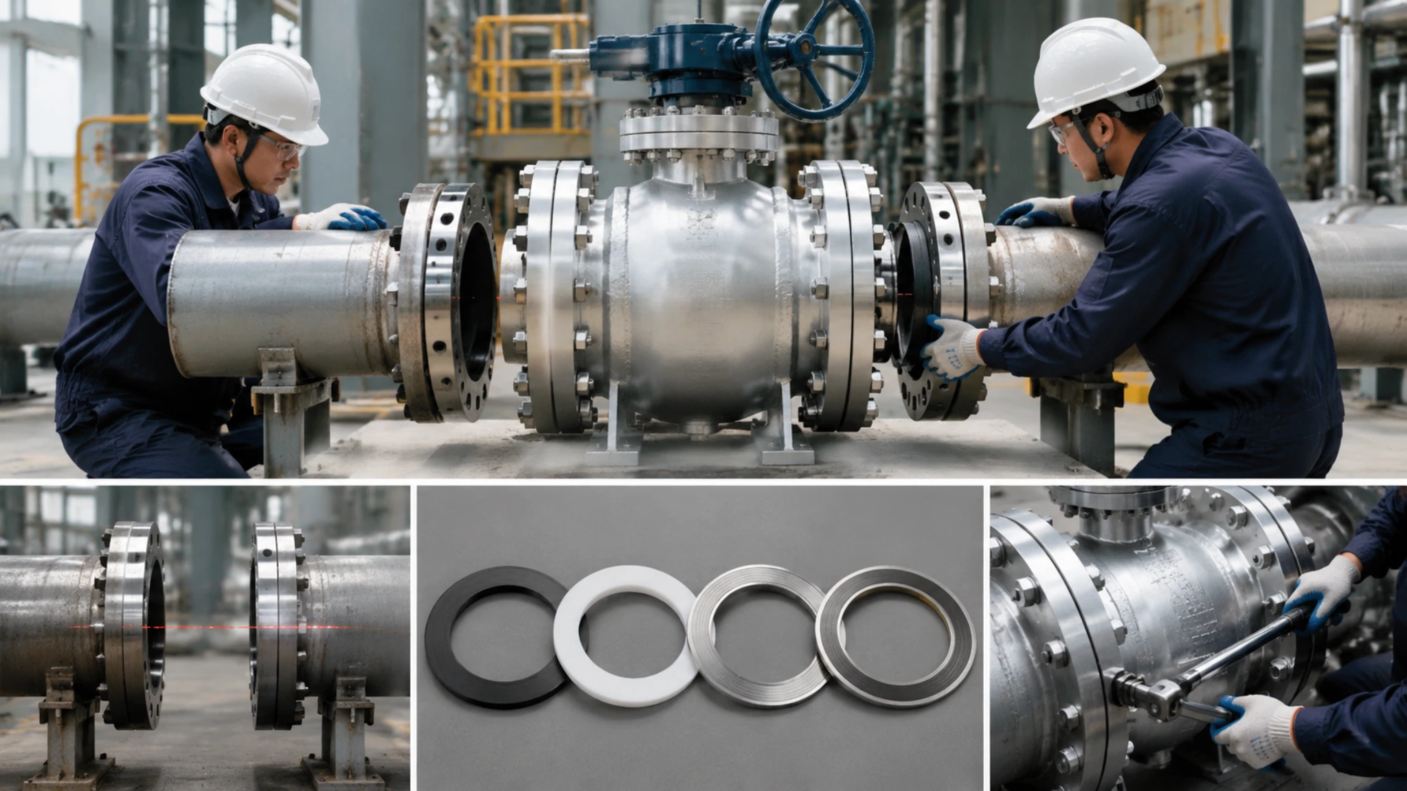
Seals (FFKM 200°C+ + ISO 15848-1 Class B)
Ball valve stem seals (packing) and body seals (gaskets) involve many non‑metallic materials. In sour gas, the corrosion resistance of these materials is often the easiest link to be overlooked during selection.
- Stem packing usually uses braided graphite or PTFE V‑rings. Both have good chemical stability in H2S. Graphite working temperature range: –200°C to +450°C; PTFE: –200°C to +260°C.
- But ordinary PTFE suffers from stress cracking under high‑temperature, high‑pressure H2S conditions and is not suitable for stem seals. Modified PTFE (e.g., glass‑fiber or carbon‑fiber reinforced) or perfluoroelastomer (FFKM) must be used.
Perfluoroelastomer products (Kalrez, Chemraz) perform excellently in aggressive sour gas service above 200°C, but the price is 8–12 times that of ordinary elastomers. A full life‑cycle cost assessment is needed before decision‑making.
Another key parameter in seal selection is the pressure‑temperature combination limit.
The combined effect of H2S partial pressure and temperature accelerates elastomer aging: for every 20°C increase in temperature, the H2S diffusion rate approximately doubles.
- When we selected seals for a Middle East sour gas project, we performed type testing on stem seals per ISO 15848‑1. The actual leakage rate was below 1×10⁻⁴ Pa·m³/s, fully meeting Class B seal level requirement.
- Seals also require certification. Suppliers must provide material compatibility proof for sour gas (usually per NACE TM0187 or ASTM D1414), confirming no excessive volume swelling or hardness change under expected service conditions.
For critical ball valve stem seals, it is recommended to require the supplier to provide accelerated aging test reports in H2S, ensuring the aging amount over a 10‑year service life remains within 10%.
Testing and Certification (SSC + HIC + File Links)
SSC Resistance Testing (NACE TM0177 + Solution A 720 Hours)
Sulfide Stress Cracking (SSC) testing is the core step to verify metallic material resistance in sour environments. Test method follows NACE TM0177.
- The standard specifies four test solutions (A, B, C, D). Among them, Solution A (5% NaCl + 0.5% glacial acetic acid, saturated with H2S) is the most common in industry. The test period is 720 hours (30 days).
- Samples are placed under constant load (usually 80% of material yield strength) in the test solution, and observed for cracks or fracture.
- Acceptance criteria: no fracture in the bent specimen; crack length ≤ 0.1 mm (under 200× magnification).
ASTM G38 (C‑ring) and NACE TM0177 Type A (tensile bar) are the two most common specimen shapes.
ISO 15156‑3 clearly stipulates: when H2S partial pressure > 0.01 MPa, Group 1 materials must pass SSC laboratory certification.
However, Annex A of ISO 15156‑1 also provides a hardness‑based exemption route – if the maximum Rockwell hardness of the material is ≤ 235 HB and the chemical composition meets Annex A requirements, SSC testing may be omitted.
In a sour gas project procurement, we negotiated with the owner many times – the owner insisted on SSC test reports, even if hardness was within limits, to have a double safety net.
The final compromise was:
- For Class 300 to Class 600 LCB valve bodies, provide hardness compliance certificate (owner accepted exemption).
- For Class 900 and above WCC valve bodies, add the 720‑hour NACE TM0177 Solution A SSC report as requested by the owner.
The validity period of the test report is also important. The standard does not specify a time limit, but if the material batch changes (especially the steel mill heat number), re‑evaluation is required.
HIC Resistance Testing (NACE TM0284 + CTR ≤ 2%)
Hydrogen Induced Cracking (HIC) testing is used to evaluate the resistance of metallic materials to hydrogen atom diffusion and internal crack propagation. Test method follows NACE TM0284.
- Test solutions: NACE Solution A (5% NaCl + 0.5% glacial acetic acid, saturated with H2S) or Solution B (synthetic seawater + acetic acid + H2S). Test period is 96 hours (4 days).
- HIC specific indicators: Crack Sensitivity Ratio (CSR), Crack Length Ratio (CLR), and Crack Thickness Ratio (CTR). CTR is the most critical indicator; ISO 15156‑3 requires CTR ≤ 2% to be compliant.
- After testing, the specimen surface is inspected at 30× magnification, and a cross‑section is cut to observe internal crack distribution at 20× magnification.
HIC cracks are parallel to the rolling direction, showing strong directionality, and can be clearly distinguished from the brittle crack shape of SSC.
During our incoming inspection of offshore pipeline ball valves, we found that the actual CTR of WCC valve body castings was 4.7%, exceeding the permitted standard. We immediately initiated the non‑conforming product procedure, traced back to the original material batch, and found that the sulfur content was too high due to poor slag removal control during melting.
HIC testing sampling location and direction have strict requirements:
- Samples must be taken from the most unfavorable stress location of the valve body.
- The relationship between rolling direction and force direction must be consistent with actual service.
- For welded components (valve body and end cap welds), HIC testing must be sampled separately from base metal, heat‑affected zone (HAZ), and weld metal. The CTR acceptance standard for base metal is the same as for the weld.
For large valve bodies with thickness exceeding 50 mm, special attention must be paid to delamination resistance in the rolling direction (Z‑direction); the Z‑direction tensile reduction of area must be ≥ 35% (per ASTM A770).
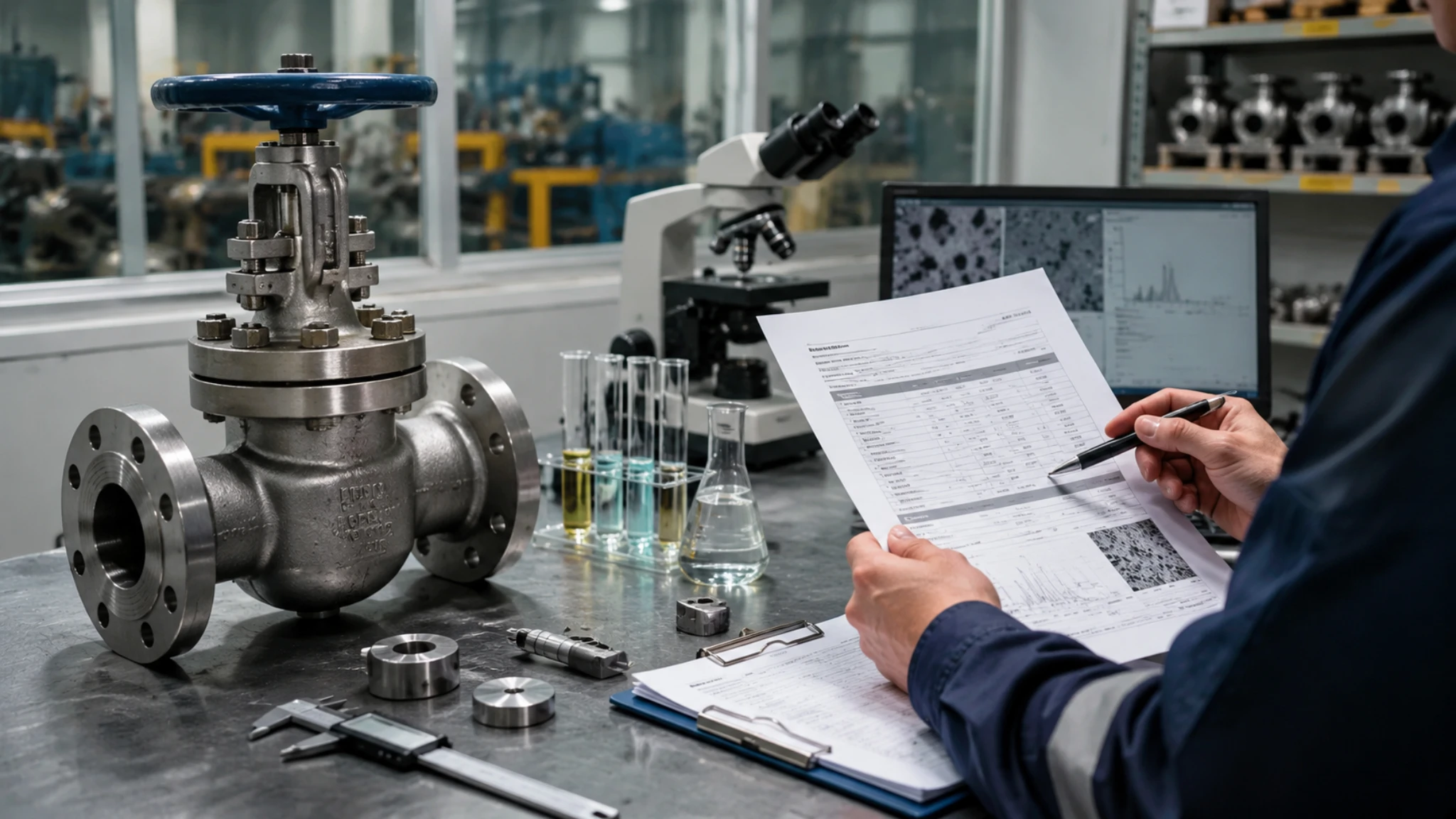
During our supervision, we established a fast screening method: use a 500× metallographic microscope to check the inclusion content of each casting batch (typically A‑type, B‑type inclusions ≤ 2.5 grade).
Batches with high inclusion content have a higher HIC risk, so they are prioritized for the TM0284 formal test.
Release Documentation (MTC + Type 3.1 + Traceable Batch Numbers)
Release documentation for sour‑service ball valves is the final proof of material compliance. These documents must be complete, signed, and shipped with the goods before delivery.
The procurement specification (PR) must clearly list the required document set. International projects usually follow ISO 10474 (Steel castings – Inspection documents) or EN 10204 (Metallic products – Inspection documents).
For Class 300 and above ball valves, it is recommended to request the following five types of documents:
- MTC (Material Test Certificate) – certifying that chemical composition (cast analysis + product analysis) and mechanical properties (tensile strength, yield strength, elongation, impact energy) meet design requirements.
- Heat treatment report – stating heat treatment condition (normalized / normalized + tempered / quench + tempered), heat treatment batch number, holding temperature, and holding time.
- Hardness test report – providing hardness values of the valve body pressure‑bearing area (random three‑point average not exceeding 235 HB).
- Welding procedure qualification records (WPS + PQR) – covering all qualified welding ranges.
- NACE MR0175/ISO 15156 compliance declaration – signed by the manufacturer’s quality manager, certifying that all supplied valves fully meet the standard requirements.
EN 10204 divides certificates into Type 2.1, Type 2.2, and Type 3.1.
Type 3.1 is an inspection certificate signed by an independent inspection body (NOTIFIED BODY). Critical valves for sour service usually require Type 3.1.
For domestic projects in China, CNPC and Sinopec generally accept MTCs issued by the manufacturer’s own laboratory, but require inspection personnel (CWI or equivalent) to witness critical testing processes on site.
Release documents must also include the traceability identification of each valve – the heat number stamped on the valve body must match the heat number on the MTC one‑to‑one.
During our document review for a large sour gas project, we found that the manufacturer had replaced individual valve certificates with batch reports, making it impossible to trace which valve corresponded to which heat of steel. We eventually had to require the manufacturer to supplement individual material certificates and redo the document filing before this issue could be resolved.

")