
API 6D ball valves are critical isolation equipment in pipelines. Actuator selection directly impacts system operational reliability and construction costs.
This guide comprehensively covers valve selection for sizes ranging from DN50 to DN1200 and pressure ratings from Class 150 to Class 900. It provides a comparative analysis of the three mainstream actuator solutions: pneumatic, electric, and hydraulic.[1]
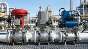
Three Types of Actuators
To give you an intuitive understanding of the core differences among the three types of actuators, here is a cross-comparison of their key parameters:
| Actuator Type | Typical Output Torque Range | Common Switching Speed / Time | Best Application Conditions |
|---|---|---|---|
| Pneumatic Actuator | 50 ~ 3000 Nm | 0.5 ~ 3 seconds | Oil and gas transmission pipelines, chemical plant explosion-proof zones, and scenarios requiring rapid Emergency Shutdown (ESD). |
| Electric Actuator | Depends on power (0.05 ~ 3 kW) | 15 ~ 30 seconds (e.g., DN200) | Scenarios requiring precise multi-stage adjustment and high opening accuracy control (e.g., desalination, LNG receiving stations). |
| Hydraulic Actuator | Easily exceeds 10,000 Nm | 8 ~ 20 seconds (e.g., DN800) | Large-diameter high-pressure valves (DN700+ / Class 900+), deepwater production, and subsea pipelines. |
Pneumatic Actuators: Key Characteristics
Pneumatic actuators are the most widely used option in oil and gas transmission pipelines.
In many station modification projects consisting of DN200 to DN600 pipelines, double-acting pneumatic actuators are uniformly adopted.
The conventional air supply pressure ranges from 5 to 8 bar. The output torque spans from 50 to 3000 Nm, which can directly drive the opening and closing of API 6D ball valves.
Its action response is very fast, with switching times generally between 0.5 and 3 seconds. This serves as a rigid indicator for emergency shutdown (ESD) conditions requiring instantaneous isolation.
Structurally, pneumatic actuators mainly include the following core components:
- Cylinder
- Piston
- Spring Return Mechanism
The pneumatic output torque varies linearly with the air supply pressure. For every 1 bar drop in supply pressure, the output torque decreases by about 10% to 15%.
Single-acting actuators with spring returns are ideal for “fail-safe positioning” scenarios. For example, in fire and gas systems, if the air supply pressure is suddenly lost, the valve will automatically close via spring force.
Core Point to Note: The torque of API 6D ball valves is usually divided into Breakaway Torque (to overcome initial seat friction) and Running Torque (to maintain switching friction). Their values typically differ by 1.5 to 2 times.
During selection, the rated torque of the pneumatic actuator must be at least 30% greater than the breakaway torque to serve as a safety factor.[2]
High explosion-proof performance and reliability are the core advantages of pneumatic actuators.
In flammable and explosive areas with Class IIA/IIB gases, such as chemical plants and refineries, pneumatic actuators do not rely on electricity. They do not produce electric arcs or high-temperature surfaces during operation, allowing them to directly meet the strict explosion-proof requirements of ATEX Zone 1/2 or IECEx Ex d.[4]
In contrast, electric actuators contain internal motors and contactors, presenting a certain ignition risk during operation or when the enclosure cover is opened.
In addition, air consumption is a factor that must be accurately calculated during selection. For example, a DN300 ball valve requires about 80 to 150 NL (Normal Liters) of compressed air for a single cycle.
For high-altitude stations or areas with insufficient local air supply, the system must be configured with an additional air storage tank of sufficient capacity.
The disadvantage of pneumatic actuators is their abrupt power characteristics. They generate significant pressure shocks at the moments of starting and stopping, which usually causes slightly greater wear on the valve stem seals compared to electric actuators.
In recent years, as pipeline pressures have risen to Class 600 ~ Class 900, the required torque for API 6D high-pressure ball valves has exceeded 5000 Nm.
In this case, the size of large pneumatic actuators becomes extremely bulky, and the overall burden on the air supply system becomes too heavy. Therefore, hydraulic solutions should be prioritized.
Electric Actuators: Ideal Use Cases
Electric actuators are ideal for special conditions requiring precise position control and multi-stage continuous actions.
In desalination plants and LNG receiving stations, valves often do not need simple full opening or full closing. Instead, they need to execute multi-step staggered adjustments, such as opening to 25% and holding for 10 seconds, then continuing to open to 50%.
Electric actuators integrate high-precision gearboxes and drive circuits internally.
Through 4~20 mA analog signals or fieldbus (PROFIBUS/Foundation Fieldbus) communication, the valve can stop precisely at any preset opening, with positioning accuracy controlled within ±1%.
Electric actuators do not need to be equipped with complex compressed air systems. They can directly utilize the factory’s existing power supply, saving owners the high initial cost of building dedicated air compressor stations.
In a 2023 desalination project in Zhejiang, electric actuators were comprehensively selected because the site lacked the infrastructure for laying compressed air pipelines.
In the later commissioning stage, technicians finely adjusted the valve characteristic curves using the HART protocol. They successfully reduced the linear error to 0.8%.
Smart Monitoring Advantage: Electric actuators can output and display the current torque value in real time. This provides an early warning for abnormalities such as valve stem jamming, which traditional pneumatic actuators cannot do.
When selecting an electric actuator, two key parameters directly determine its performance:
- Rated Power: The conventional specification power ranges from 0.05 to 3 kW. Greater power yields higher output torque, but the capacity margin of the power supply transformer must be considered. The starting current of high-power actuators is often 5 to 7 times the rated current, which can cause instant shocks to the plant’s power grid.
- Protection Level: For outdoor installation, IP67 is the basic requirement. However, if the project is in rainy southern regions or coastal salt spray environments, IP68 is strongly recommended, along with an anti-corrosion coating. The motor bearings should also use stainless steel materials.
In LNG receiving stations with ultra-low temperature media pipelines of -162°C, electric actuators must be equipped with space heaters to prevent internal condensation. The heater power is typically between 30 and 100 W to maintain the internal ambient temperature above 0°C.
The switching speed of electric actuators is significantly slower than that of pneumatic ones.
Taking a DN200 ball valve as an example, an electric actuator may take 15 to 30 seconds to complete a full open or close action. For emergency shutdown conditions, designers must strictly check whether this action time meets pipeline safety transportation specification requirements.
When to Choose Hydraulic Actuators
Hydraulic actuators are the irreplaceable mainstream solution for large-diameter, high-pressure ball valves.
In API 6D specifications, for ball valves of DN700 and above, or Class 900 and above, pneumatic actuators either lack sufficient torque or are too bulky for on-site installation. In these cases, the hydraulic solution becomes a necessity.
The working pressure of the hydraulic cylinder is typically between 10 and 21 MPa, and its output torque can easily exceed 10,000 Nm.
A single conventional-sized hydraulic actuator can fully cover the requirements for ball valve specifications from DN700 to DN1200.
The hydraulic system also possesses a unique advantage: it can provide an extremely constant output torque, completely unaffected by fluctuations in the external power source pressure. In contrast, the torque of pneumatic actuators drifts with changes in air supply pressure, making hydraulic actuators perform better in stability.
Almost all subsea pipelines and deepwater production facilities prioritize hydraulic actuators.
This is because in deep-sea environments, the external seawater pressure can be directly utilized as a hydraulic power source. This eliminates the trouble of configuring complex air or power sources from the surface.
The overall system structure of hydraulic actuators is much more complex than that of pneumatic and electric ones. Its core components include:
- Hydraulic Cylinders
- Hydraulic Power Unit (HPU) / Pump Station
- Integrated Control Valve Blocks
- Oil Tank and High-Pressure Piping Accessories
The driving power of the pump station is generally between 3 and 15 kW. Commonly used hydraulic oil grades are ISO VG 46 or VG 68. The specific viscosity selection depends on the ambient temperature range of the project site.
Safety Core: The Accumulator in the hydraulic system is the top priority of the design. In extreme conditions such as sudden power loss or complete failure of the pump station, the accumulator must store and provide enough oil to support at least 3 full-stroke operations of the valve, ensuring safe system closure.
This capability to ensure safe valve action when losing the external main power source is called “fail-safe capacity.” During technical selection negotiations, this must be clearly requested from the hydraulic supplier and strictly verified.
The action response speed of hydraulic actuators is between that of pneumatic and electric ones. For example, driving a DN800 pipeline ball valve, its switching time is usually stably maintained between 8 and 20 seconds.
It should be noted that on-site standalone commissioning of hydraulic systems highly tests the professionalism of personnel. Moreover, minor oil leakage risks are also a troublesome pain point in subsequent field maintenance.
Selection Parameters
Torque Calculation
Torque calculation is the first step in actuator selection and also the most error-prone aspect of the entire engineering process.
The total friction torque actually required during the opening and closing of an API 6D ball valve consists of the cumulative sum of three parts:
- Seat Torque (accounts for the major share of the total torque)
- Packing Torque
- Bearing Torque
The seat torque is closely related to the valve size, operating pressure rating, sealing surface materials (e.g., tungsten carbide hard seal versus soft seal), and the lubrication characteristics of the fluid medium.
Typical Comparison Example:
- For a common DN300 Class 300 carbon steel ball valve under soft seal conditions, the seat torque is approximately 450 to 650 Nm.
- However, for a valve of the exact same specification using metal seats (hard seal), the friction torque may soar significantly to 900 to 1200 Nm.
The packing torque depends on the stem diameter and the type of packing selected. For example, high-sealing graphite packing generates about 30% more stem friction than traditional PTFE (Teflon) packing.
When selecting an actuator, the actual breakaway torque data provided by the valve manufacturer must be strictly followed. Upfront estimations using empirical formulas are strictly prohibited.
A catastrophic and common mistake in the industry is mistakenly using the “running torque” during normal operation as the initial “breakaway torque” for actuator sizing. This completely distorts the pre-reserved safety factor.
Comprehensive torque calculation must also incorporate temperature correction factors and operating frequency correction factors:
- Temperature Correction: At high temperatures exceeding 150°C, the elastic seat elastomer will soften. The initial breakaway torque may be 20% to 40% higher than at room temperature, requiring reference to the manufacturer’s temperature correction curves.
- Frequency Correction: If the valve’s daily operating frequency exceeds 10 times/day, the seat friction surface will heat up and expand under repeated friction. The calculated torque must be multiplied by a frequency correction factor of 1.15 to 1.25.
Although the API 6D specification itself does not provide rigid quantitative rules for the output torque of actuators, long-distance pipeline owners consistently require the actuator’s rated output torque to be 1.5 to 2.0 times the calculated torque value as a safety margin.
In actual engineering projects, my standard operation is to require both the valve manufacturer and the actuator manufacturer to independently issue a complete torque calculation report.
After checking and confirming that the data error between the two parties is strictly controlled within 10%, we can proceed to sign the technical agreement. Otherwise, if both parties insist on their own opinions, it will not be discovered until the on-site integrated commissioning that the actuator cannot move the valve, leading to an extremely passive dilemma.
Switching Time Requirements
Switching time is a rigid technical indicator of whether the actuator can meet the process safety flow.
In extreme Emergency Shutdown (ESD) conditions, the valve must achieve full closure within 3 seconds of receiving the system trigger signal. In conventional process control conditions, an action time of 5 to 30 seconds is completely acceptable.
The switching time of a pneumatic actuator mainly depends on the cylinder’s internal volume and the actual diameter of the on-site air supply pipeline.
If a conventional DN6~8 air supply hose is used, the inflation action time for a DN300 pneumatic actuator is about 1.5 to 2.5 seconds, and the deflation time is about 1 to 2 seconds. The combination of both constitutes the total switching time.
If the air supply line is laid too long (e.g., exceeding 20 meters), long-distance pressure losses will cause the actuator to slow down significantly. In this case, a DN10 or larger pipeline must be used, or an independent air storage tank must be installed directly at the actuator end.
The switching time of an electric actuator is determined by the motor’s rated speed and the gear ratio of the external gearbox.
For a conventional 0.25 kW motor combined with a 1:200 gearbox, driving a DN200 ball valve typically takes 15 to 25 seconds. Engineering adjustments can compress this time to 8 to 12 seconds by increasing the motor power or reducing the transmission ratio.
Key Commissioning Point: The final verification test of the actuator switching time should be conducted during the integrated system linkage testing stage after all on-site components are assembled. It must never rely solely on the actuator manufacturer’s standalone no-load test data at the factory.
In factory testing, the single-unit acceptance action time of a pneumatic actuator may only take 3 to 5 seconds. However, when connected to a massive ball valve on site, combined with the pressure drop losses of long air pipelines and signal transmission delays from control solenoid valves (which usually require 50 to 100 ms to respond), the actual system-level response time often doubles.
In LNG receiving stations and subsea core pipelines, systems usually have strict Safety Integrity Level (SIL) time limits:
- For SIL 2 ESD valve systems, the total response time must not exceed 2 seconds.
- For SIL 3 highest safety systems, the total response time is strictly controlled within 1 second.
Note that this time includes the total accumulated time from sensor detection of abnormality, central logic solver making the shutdown decision, actuator response action, to the valve being fully and tightly closed on site.[3]
When fine-tuning the switching time on site, there is another easily overlooked detail: the trigger points of the electrical limit switches should be adjusted based on the actual physical fully open and fully closed positions measured on site, rather than rigidly aligning with the theoretical geometric positions on the scale.
Under actual high-pressure conditions, the valve stem may produce a physical displacement deviation of 2 to 5 mm due to media pressure and thermal expansion/contraction. If not adjusted accordingly, the limit switch may trigger prematurely, causing the control room to mistakenly believe the valve is closed when it is not fully engaged on site.
Explosion-Proof Ratings
An incorrect selection of explosion-proof ratings can lead directly to an immediate shutdown and rectification order by safety inspection authorities.
In petrochemical plants, electrical explosion-proof designs must fully comply with the standard system equivalent to IEC 60079 (such as GB 3836). For environments with explosive gases, flameproof “d” or intrinsic safety “i” types are usually used; for dust conditions, tD or IP protection codes are used.
Pneumatic actuators themselves are composed entirely of mechanical metal parts and contain no electrical circuits, so the standalone unit usually does not require a special explosion-proof certification.
However, the control solenoid valves (used to switch air circuits) and position transmitters (used to feed back valve open/closed status) installed with it must possess valid explosion-proof certificates.
Control solenoid valves are uniformly selected as Ex d IIC flameproof type, with common control voltages of 24 VDC or 220 VAC, and rated power between 5 and 10 W. When selecting, special attention should be paid to checking the applicable surface temperature class (T1~T6), where the T6 class limits the maximum surface temperature to 85°C, providing the highest inherent safety in hazardous flammable media environments.
Position transmitters (also called limit switch boxes) are mainly divided into mechanical and inductive types on site:
- Mechanical limit switches: Rely on stem rotation to directly trigger internal microswitches; simple structure and low cost, but physical action lifespan is limited (conventionally about 100,000 times).
- Inductive limit switches: Use non-contact proximity switches; extremely long lifespan and highly reliable operation, but initial procurement costs are relatively high.
The complexity of explosion-proof selection for electric actuators is an order of magnitude higher than that for pneumatic ones.
Currently, the mainstream industrial explosion-proof designs for electric actuators include the following three categories:
- Flameproof (Ex d): Its high-strength electrical metal enclosure must withstand the instantaneous pressure of an internal explosion and guarantee that absolutely no spark leaks out. This type has the highest technical cost but also the best operational reliability.
- Increased Safety (Ex e): It does not possess the ability to prevent internal ignition. Instead, it reduces external ignition risks by significantly improving the mechanical protection requirements of the enclosure and the insulation performance of wiring terminals, with a moderate manufacturing cost.
- Intrinsic Safety (Ex i): Limits the instantaneous energy of internal electronic circuits so that it is always below the ignition energy threshold of the medium to achieve explosion protection. This requires the entire associated loop (field sensor + safety barrier controller + actuator) to fully meet intrinsic safety certification, making system integration design highly complex.
The explosion-proof level of actuators for API 6D valves must precisely match the hazardous area classification diagram (Zoning Diagram) issued by the plant’s safety department:
- In Zone 1 areas (where explosive gases appear frequently): Electrical components are mandatory to reach Ex d or Ex i levels.
- In Zone 2 areas (where explosive gases rarely appear): Ex d, Ex e, or nA (non-sparking) actuators can be used.
In addition, design personnel should pay special attention to the maximum surface temperature class of explosion-proof actuators. T4 (130°C) can cover the vast majority of conventional petroleum derivatives, while for specific high-hazard media with extremely low auto-ignition temperatures like ethers and carbon disulfide, the actuator must be forced to meet the T6 (85°C) class. When placing an order, be sure to request the formal explosion-proof certificate from the supplier and check the list of applicable gas media.
Installation and Commissioning
Actuator Mounting Orientation
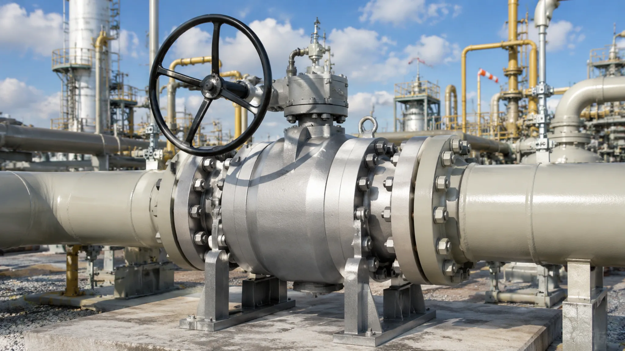
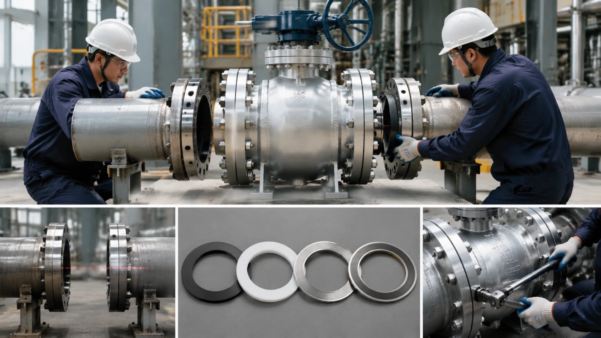
The installation direction of the actuator seems simple, but if installed incorrectly, the consequences can be very severe.
API 6D valves usually have strictly specified media flow directions, indicated by arrows cast on the valve body. If the actuator direction is reversed, it will cause the valve sealing surfaces to bear asymmetrical squeezing stress during closure, thereby accelerating seat wear and even leading to serious internal leakage after closure.
Standard specifications require that the actuator’s output main shaft must be perfectly concentric with the valve stem, with the concentricity error strictly controlled within 0.1 mm. Otherwise, during long-term repeated opening and closing cycles, the stem will bear continuous lateral shearing force, causing the stem packing to wear out and leak prematurely.
For pneumatic actuators, special attention should also be paid to the orientation of the air supply inlet and exhaust ports.
Double-acting pneumatic actuators have no strict restrictions on orientation, but for single-acting actuators with spring returns, the installation must be repeatedly checked and confirmed: in the extreme state of losing air pressure, the reset force generated by the spring can accurately push the valve to the preset fail-safe (FAIL SAFE) position.
After overall installation is complete and before connecting the air supply for the first time, it is strongly recommended to use the mechanical handwheel to manually operate the valve through two to three full-stroke opening and closing tests to ensure there is no internal jamming or abnormal noise.
Another detail often overlooked during construction is the physical visibility of the valve position indicator (Indicator). The position indicator rod of a ball valve usually extends from the top of the actuator.
When determining the installation orientation of the actuator, it must be ensured that the indicator can be clearly seen from the side of the main inspection walkway without any blind spots. This allows field inspection personnel to accurately judge the true open/closed status of the valve at a glance without using any tools.
In some substandard engineering projects, the actuator is installed directly above the pipeline, making it impossible for personnel to reach during subsequent maintenance, or the indicator is completely blocked by upper intersecting pipelines. Every inspection requires maintenance personnel to set up temporary scaffolding or ladders, which is highly inconvenient.
In addition, for actuators installed outdoors year-round, full consideration must be given to the negative impact of seasonal sun and rain on the air supply lines.
In cold winters, trace amounts of condensed water in the air supply lines can easily freeze at pipeline low points and lead to complete blockage of the entire air path. Therefore, it is strongly recommended to install an automatic drain valve (steam trap) on the main air supply pipeline and equip a dedicated metal rain shield under the local solenoid valve.
Limit Switch Wiring
Wiring and calibration of the limit switches (position transmitters) is one of the steps most prone to low-level errors during the on-site instrumentation commissioning phase.
Traditional mechanical limit switches are usually equipped with two or four independent sets of electrical contacts externally, each set containing the following three terminals:
- COM (Common)
- NO (Normally Open)
- NC (Normally Closed)
Before wiring construction, instrumentation personnel must use a multimeter to perform actual measurements, accurately verify, and mark which sets of terminals correspond respectively to the valve’s physical fully open position and fully closed position.
The most common low-level error on site is reversing the NO/NC contacts for the fully open and fully closed positions. This causes the logic feedback signal received by the control system to be completely opposite to the true field status — even though the valve is tightly closed on site, the central control room’s DCS screen incorrectly displays it as fully open.
电气接线应当统一使用专用的防爆挠性管引入执行器内部。接头处必须使用专用的防爆胶泥(适用于 Ex d 隔爆区)或高质量的硅胶密封圈(适用于 Ex e 增安区)进行严密灌注封堵,绝对禁止使用普通的绝缘黑胶布进行简单缠绕。
Electrical wiring should be uniformly introduced into the actuator using dedicated explosion-proof flexible conduits. Joints must be tightly sealed and potted using dedicated explosion-proof putty (applicable to Ex d flameproof zones) or high-quality silicone sealing rings (applicable to Ex e increased safety zones), and the use of ordinary electrical tape for simple wrapping is absolutely prohibited.
The 24 VDC weak control signal lines should use twisted-pair shielded cables, and the shielding layer of the cable must be strictly single-point grounded at the control cabinet end. This can effectively prevent electromagnetic and harmonic interference generated by large field equipment such as frequency changers from causing false alarms in the control system.
During the commissioning of a natural gas gate station project in Zhejiang in 2022, it was found that the valve feedback signals fluctuated frequently and irregularly on the control room screen.
Ultimately, it was traced back to strong electrical harmonic interference from the adjacent variable-frequency water pump room. The signal drift problem was completely resolved by targeted installation of instrument signal isolators inside the control cabinet.
Although the on-site wiring of intelligent bus-type limit switches is greatly simplified compared to traditional mechanical ones, their subsequent software parameter configuration is more critical.
Feedback devices based on Foundation Fieldbus (FF) or PROFIBUS PA buses only require two bus signal cables connected in series, completely saving the trouble of pulling long-distance multi-core signal cables for each valve individually.
However, this requires automation engineers to pre-import and correctly configure the corresponding Device Description (DD) files in the DCS system, and precisely allocate node tag numbers and ranges in the network. Intelligent feedback devices can also return analog torque values (4~20 mA) to the system, making it easy for the control system to monitor the changing trend of actuator torque in real time, which is extremely useful for early detection of seat jamming and fouling. However, it must be particularly emphasized that this analog signal should be routed separately from the digital bus signal, and do not bundle it directly inside the bus cable.
After wiring and software configuration are completely finished, a strict I/O channel point-to-point verification must be performed on the DCS side: send full open and full close commands to each valve, and carefully verify whether the valve status, action time, and torque signals displayed on the DCS screen are completely consistent with the actual field conditions.
Integrated System Testing
Integrated system linkage testing is the final barrier before the actuator is officially put into production operation, and it is also the stage where various design hazards are most likely to manifest collectively.
A sound linkage test should be carried out step-by-step strictly according to the following three levels:
- Actuator standalone no-load action test
- Local linkage test of the valve with local pneumatic/electrical circuits
- Overall system-level integrated linkage test with DCS or ESD safety systems
Standalone testing refers to directly powering or supplying air to the actuator locally, manually sending open and close signals, and observing whether its mechanical action is smooth, whether limit switches trigger accurately at design positions, and whether local indicators show precisely.
Local air circuit linkage needs to focus on confirming: the air path switching response time after the control solenoid valve loses or gains power (usually should not exceed 100 ms), whether the actual inflation and deflation times of the cylinder match the valve opening and closing speeds required by the process, and whether the quick exhaust valve (quick release valve) installed locally can effectively prevent overpressure inside the cylinder.
The overall ESD system linkage test must be conducted while the central safety control system is in simulation test mode. By manually entering simulated fault signals into the ESD logic controller, strictly verify whether the total time from safety command issuance to complete and tight valve closure on site meets the rules of the SIL rating.
Another item that must absolutely not be ignored in linkage testing is the cross-system linkage verification with the Fire & Gas System (F&G System).
On modern offshore drilling platforms and large oil refineries, fire or toxic gas alarm signals will directly trigger the highest-level ESD emergency shutdown program, thereby instantaneously closing all isolation valves on relevant production pipelines.
During testing, simulate the alarm signal from the F&G detector, confirm that the actuator can complete the closing action within the specified time, and strictly verify the highest priority of the ESD command — even if the control center was performing normal opening or closing operations on the valve at that time, once the ESD signal intervenes, it must be able to immediately and unconditionally override the control right.
In addition, for actuators with fail-safe (FAIL SAFE) functions, automatic action tests under sudden power loss or air failure must also be performed.
Suddenly cut off the power supply (electric) or air supply (pneumatic) of the actuator during valve operation, closely observe whether the valve can automatically move toward the preset fail-safe direction, and confirm that no jamming or timeout phenomenon occurs throughout the entire action process.
All linkage test results should be recorded in detail in the commissioning report and formally submitted to the owner as part of the as-built documentation.
💡 Core Sizing Golden Standard:
Calculate torque first, verify time second, confirm explosion-proof third, and perform linkage testing last.* Pneumatic Actuators: Suitable for ESD rapid shutdown and high-hazard explosion-proof zones.
* Electric Actuators: Suitable for multi-stage high-precision adjustment and multi-station centralized control.
* Hydraulic Actuators: The only feasible solution under large-diameter high-pressure (DN700+ / Class 900+) conditions.The matching and verification of the actuator with the ball valve is a legal procedure that cannot be bypassed. It is strictly forbidden to skip the actual torque data of the valve manufacturer and perform blind empirical estimations.
Four-Step Selection Framework:
- Torque Verification: Ensure the rated output torque of the actuator ≥ initial breakaway torque of the valve × 1.5.
- Time Validation: ESD shutdown conditions require ≤ 3 seconds, while conventional process conditions allow 5~30 seconds.
- Explosion-Proof Confirmation: Must strictly match the plant’s hazardous area classification (Zone 1/2) and media auto-ignition temperature group (T4/T6).
- Linkage Testing: Conduct integrated verification from standalone unit, local circuits, to overall DCS/ESD systems during the commissioning phase.


")