
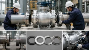
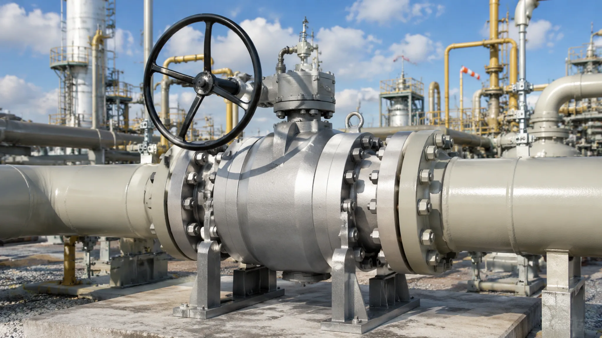
The installation quality of large-diameter flanged ball valves (above DN300, Class 150~Class 600) directly determines the sealing reliability of the pipeline system.
Unlike small-diameter valves, large-diameter flange joints require higher bolt preload forces and larger gasket areas. Any procedural deviation will be amplified during high-temperature and high-pressure (Max 550°C / Class 2500) operations.
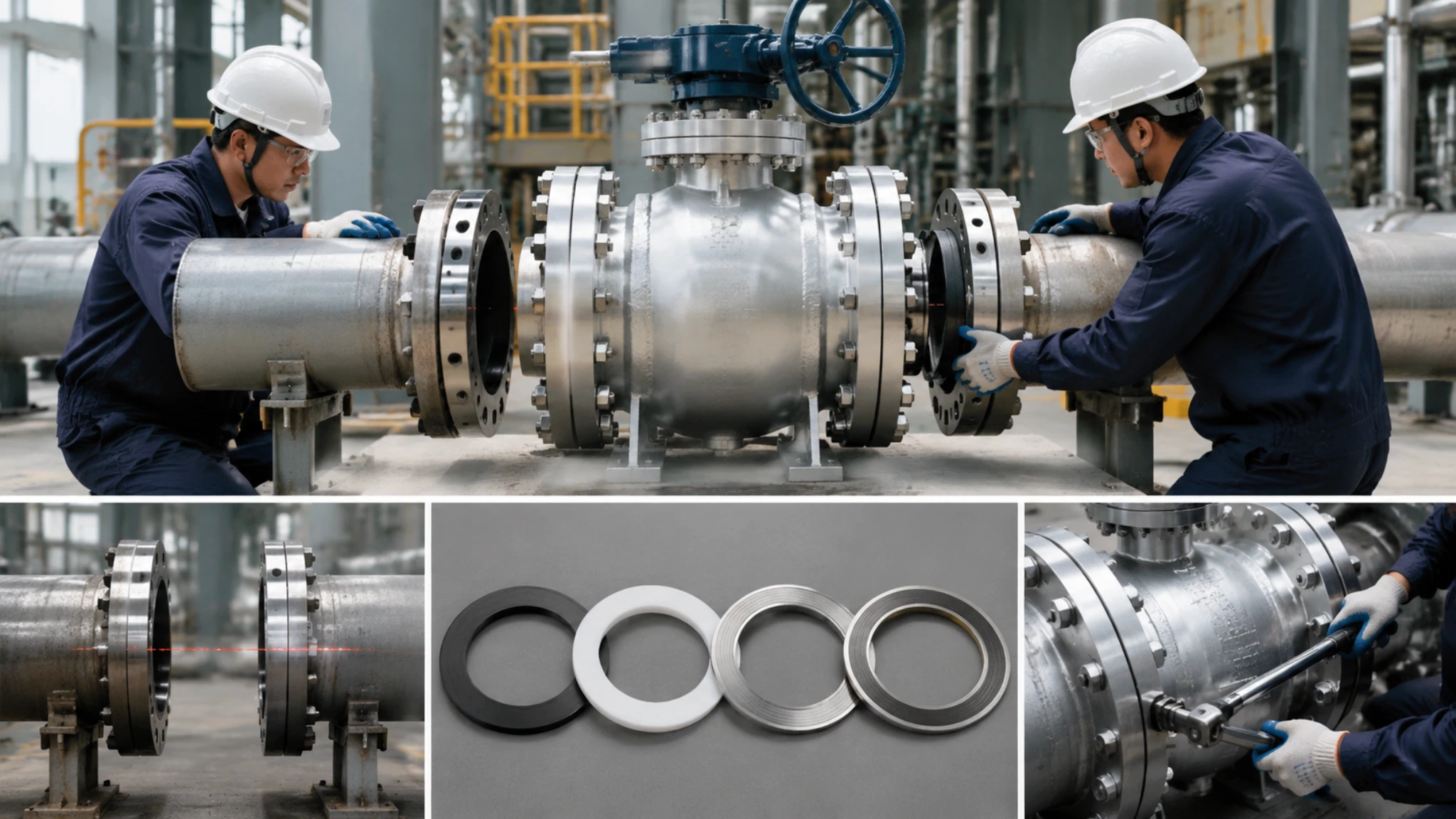
This article systematically outlines the standard installation process for large-diameter flanged ball valves. It covers preparation before installation, installation steps, and post-installation inspection. Five key aspects are included: pipe alignment, flange cleaning, gasket selection, torque control, and pressure test verification.[1]
Real case reminder: In the pipeline installation practices of several petrochemical projects, we experienced a typical alignment error firsthand — during the installation of a DN400 Class 600 ball valve in an ethylene cracking unit, a pipe axis deviation of 1.2mm (standard allowable value is 0.8mm) caused the valve body sealing surface to leak after the initial temperature rise. After reworking and replacing the valve body, strictly executing the alignment process described in this article resulted in a zero leakage rate for similar subsequent valve installations.[2]
Pre-Installation Preparation
Pipe Alignment Inspection
Key data: Over 60% of large-diameter flanged ball valve installation failures occur during the pipe alignment stage.[3]
If there is an angle or offset on the pipeline flange faces, forced assembly will directly damage the valve body sealing surface, or even cause the valve stem to bend or break.
Face Runout (≤0.8mm) vs. Shaft Misalignment (≤0.8mm)
Pipe alignment inspection needs to focus on two indicators simultaneously: Face Runout and Shaft Misalignment.
The ASME B16.5 standard[4] stipulates that the concentricity deviation of Weld Neck flanges should be ≤0.8mm; the gap between mating flange sealing surfaces should be ≤0.8mm.
For field operations, it is recommended to use a steel ruler or feeler gauge for initial inspection:
- Fit the steel ruler to the outer edge of the flange and measure four points (0°, 90°, 180°, 270°).
- Insert the feeler gauge blade between the two flange sealing surfaces.
- The difference in readings is the parallelism deviation.[5]
Handling Deviations
When the deviation exceeds the allowable value, it is strictly prohibited to forcibly pry the valve body to correct the deviation.
The correct approach is: add adjustment shims on the pipeline side (not the valve side), or re-cut the pipeline joints.
Important regulation: The EN 1591 flange design standard[6] explicitly requires: it is prohibited to use the valve flange holes as lever fulcrums to apply force (refer to API SPEC 6D specification).
Flange Face Cleaning
Contaminants on the flange sealing surface are the leading cause of static seal failure. Rust, welding slag, lubricating oil, and dust particles can each embed into the gasket during the compression process, forming micro-channels for leakage.[7]
Standard Cleaning Steps
- Remove rust and slag: Use a steel or copper wire brush to remove welding slag and rust around the outer edge of the flange and bolt holes. Focus on cleaning the inner walls of the bolt holes (where foreign objects are most likely to accumulate).[8]
- Purge: Use oil-free compressed air (OAF) to blow the flange sealing surface and remove loose particles.
- Degrease and wipe: Wipe the sealing surface with a degreaser (such as acetone or professional flange cleaner), and immediately dry it with a dry non-woven cloth after removing the grease.[9]
- Inspect and refinish: Use a vernier caliper to check the sealing surface for scratches, pits, or pitting. If necessary, lightly grind with fine sandpaper (320 grit or above) and clean again.
The sealing surface roughness should reach Ra 3.2µm~12.5µm; the ISO 1302 standard[10] has specific requirements for surface texture grades.
Note: The outer edge of the flange must be free of burrs and flashes, otherwise, it will cut the outer edge of the gasket when compressed.
How to Select Gaskets
Large-diameter flanged ball valves typically use a Spiral Wound Gasket (SWG) + inner ring combination, suitable for a temperature range of -196°C to 550°C.[11]
Gasket selection requires comprehensive consideration of four dimensions: pressure rating, medium, temperature, and corrosivity.[12]
Gasket Type vs. Pressure Rating
| Flange Pressure Rating | Recommended Gasket Type | Inner Ring Material | Applicable Temperature Range |
|---|---|---|---|
| Class 150 / PN20 | Spiral Wound Gasket (SWG) | Carbon Steel (CS) | -50°C~300°C |
| Class 300 / PN50 | SWG + Inner Ring | Stainless Steel (SS) | -196°C~400°C |
| Class 600 / PN110 | SWG + Inner Ring + Inner Ring | SS 316L | -50°C~550°C |
| Class 900 / PN150 | SWG + API 607 Fire Safe | SS 316L + Graphite | -50°C~550°C |
About filler materials:
- Graphite filler: Temperature-resistant up to 550°C, suitable for high-temperature steam systems.
- PTFE filler: Temperature-resistant up to 260°C, suitable for strongly corrosive acid and alkali media.
- Mica filler: Withstands high temperatures of 1000°C, but ASME B16.20[13] requires it to be used with an inner ring to prevent oxidative spalling.
Diameter recommendation: For sizes above DN300, it is recommended to use SWG with an inner ring. The inner ring plays a role in positioning and preventing blow-out, stopping high-pressure gas from leaking through the gasket’s cross-sectional channels.[14]
Installation Steps
Bolt Insertion Sequence
Bolt insertion (according to ASME B16.5 / API SPEC 6D) is the most easily overlooked yet most impactful step in flange joint assembly.
Before inserting bolts, ensure the following:
- Bolt material matches the flange pressure rating.
- Nuts are clean and free of burrs.
- Threads are coated with lubricant (copper paste for high temperatures, graphite oil for normal temperatures).[15]
Insertion Operating Standards
- Start from the bottom of the flange (6 o’clock position). First insert the bottom bolts and tighten the nuts finger-tight, serving as a positioning reference.[16]
- Then expand upwards following the “alternating left and right” principle: Left → Right → Left → Right… making the flange faces gradually fit and center.
- After all bolts are inserted, check whether the flange gap is uniform (measure four points with a feeler gauge). If there is significant skewing, it must be loosened and readjusted; forced compression is prohibited.[17]
- Stud Bolts require flat washers on both ends, and nuts should be installed on the side convenient for torque operation.
Prohibited action: It is strictly prohibited to use the valve itself to withstand forced correction forces (the pressure-bearing boundary of valve bodies above DN300 is ≤0.5MPa). Flange docking offsets should be adjusted from the pipeline side and should not be pried using the flange holes.[18]
How Many Rounds for Torque Tightening
The bolt preload torque for large-diameter flanges is much higher than that of small-diameter ones: for a Class 600 DN300 pipeline, the torque for a single M30 bolt can reach 2500~3000 N·m.
Core principle: Multi-round tightening is a necessary measure to ensure uniform gasket compression.[19]
Torque Round Reference Table (DN300 Flange)
| Flange Spec | Bolt Spec | First Round Torque (N·m) | Second Round Torque (N·m) | Third Round Torque (N·m) |
|---|---|---|---|---|
| DN300 Cl.150 | M20 | 150 | 300 | 450 |
| DN300 Cl.300 | M24 | 250 | 500 | 750 |
| DN300 Cl.600 | M30 | 400 | 900 | 1400 |
| DN400 Cl.600 | M36 | 600 | 1300 | 2000 |
The core principle of multi-round tightening is “progressive compression”:
- First round: start with 30%~40% of the final target torque.
- Each subsequent round: progressively increase by 20%~25%.
- Usually reach the target value in 3~4 rounds.
The ASME PCC-1 standard[20] recommends an interval of at least 30 seconds between each round (according to ASME PCC-1) to allow the gasket material to fully relax (required by ISO 14313 standard).
Real case reminder: In the installation practice of a DN500 ball valve at an LNG receiving terminal, we experienced a typical torque error firsthand — skipping the multi-round steps and directly tightening to the target torque in one go caused the SWG gasket compression to exceed the design value by 25%, resulting in a through-leakage after the first temperature drop. The leakage was eliminated after reworking, replacing the gasket, and executing a 3-round tightening process.[21]
Low-temperature environment (≤0°C) note: The friction coefficient of graphite-filled SWG increases, requiring the torque value to be increased by 15%~20% to compensate for the decrease in lubricant efficiency.[22]
Criss-Cross Tightening
Criss-cross tightening (standard path for 8-bolt flanges) is the key technique to ensure the flange faces are compressed in parallel.
Principle: Tighten two bolts at diagonally opposite positions each time to compress both sides of the flange synchronously, preventing flange tilting.[23]
Standard Criss-Cross Sequence (8-Bolt Flange)
With the flange center as the origin, operate the bolts in the following sequence (tighten one at a time, complete all before entering the next round):
- Round 1 – Initial finger-tightening: tighten half a turn each in the sequence of 1→3→5→7→2→4→6→8, ensuring the flange naturally closes.
- Round 2 – Pre-tightening (30% target torque): apply force gradually in the same sequence to compress the gasket to 70% of the designed compression height.[24]
- Round 3 – Intermediate torque (70% target torque): same sequence, check if the flange gap tends to be uniform.
- Round 4 – Final tightening (100% target torque): replace the cross pattern with a star pattern to avoid the accumulation of unilateral errors.[25]
Research data: For 8-bolt flanges, the cross pattern (horizontal then vertical) can cause a tilt angle of about 0.5° on the flange face, while the star pattern (1→3→5→7→2→4→6→8→adjacent supplementary) can reduce this error to below 0.05°.[26]
Post-Installation Inspection
Flange Gap Measurement
Post-installation flange gap measurement is the most direct means of verifying flange face parallelism and gasket pre-tightening effectiveness.
Standard basis: API 598[27] stipulates that the uniformity of the flange gap must be confirmed before conducting the rated pressure test.
Gap Measurement Methods and Judgment Criteria
- Tools: Feeler gauge (0.02~1.00mm).
- Measuring points: 4 evenly distributed points on the outer edge of the flange (top/bottom/left/right sides).
- Standard: 4-point range ≤0.20mm, single point ≤1.00mm.
- If out of tolerance: loosen 2 bolts in the corresponding quadrant and retighten them in a criss-cross pattern.
- Record: Gap value, torque value, ambient temperature, archived as as-built documentation.[28]
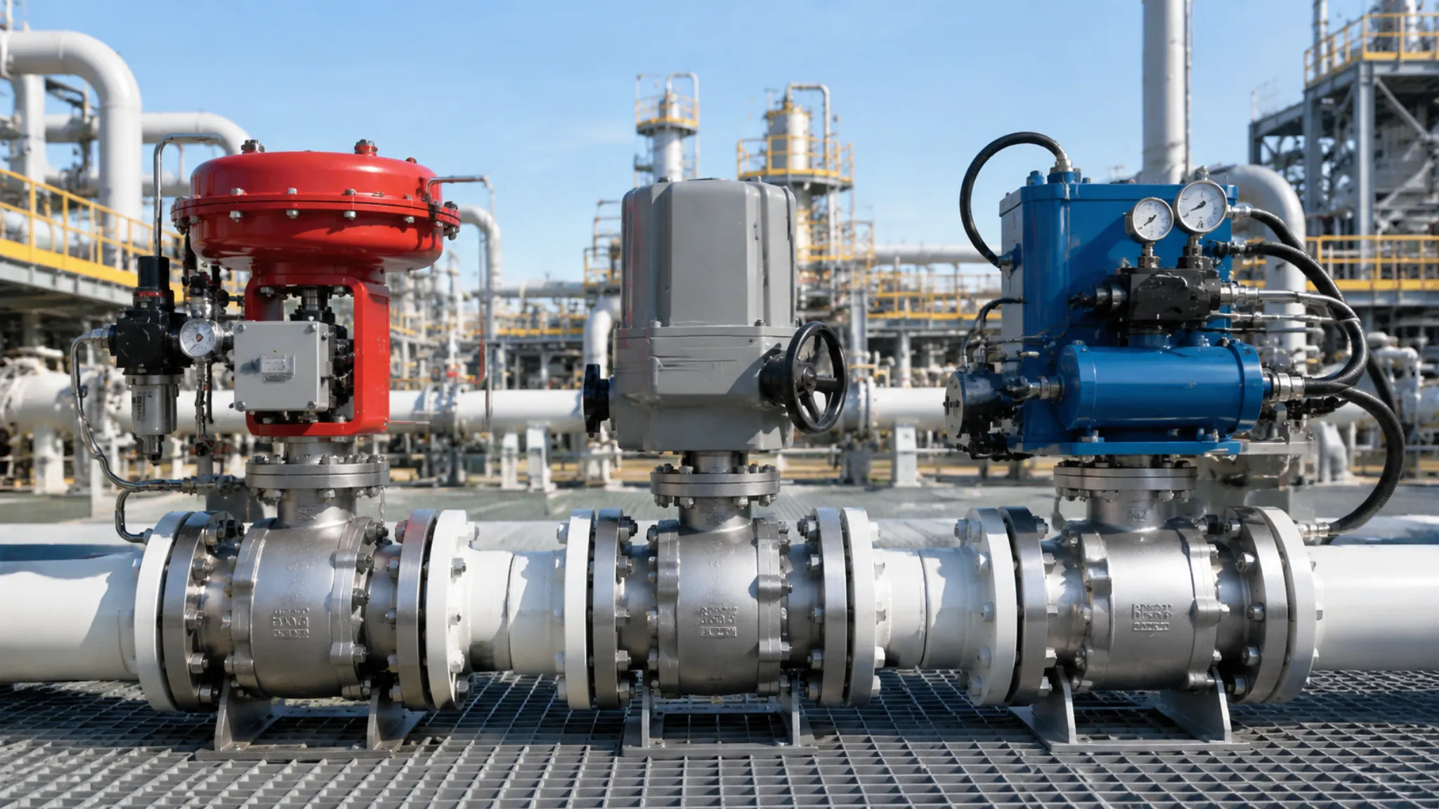
Operation Test
After flange installation is completed and pipeline purging is qualified, conduct an opening and closing operation test of the valve under cold (normal temperature) pipeline conditions to verify whether the valve stem seal and ball function are normal.[29]
Operation Test Steps
- Fully open → record turns.
- Fully close → record turns (deviation ≤10%).
- Hold pressure at fully open position for 30 seconds.
- Verify torque with 3 consecutive opening and closing cycles (deviation ≤15%).
Safety reminder: If heavy opening/closing or abnormal noise is found during operation, stop and inspect immediately. Exclude valve seat scratches or embedded foreign objects before proceeding.[30]
Pressure Test for Leakage
This is the final quality check of flange installation.
The API 598 valve pressure testing standard[31] classifies leakage into five levels.
Post-installation field pressure testing is typically executed up to 1.5 times the rated pressure (or design pressure × 1.1, whichever is lower), with a holding time of ≥30 minutes.
Real case reminder: In a hydrocracking unit modification project at a refinery, we experienced a typical insufficient pressure test issue — because the test was only performed at 60% of the rated pressure (failing to conduct the 1.5 times overpressure test as specified), the flange experienced through-leakage after only 72 hours of operation at design pressure. Investigation revealed: the gasket inner ring had undergone plastic deformation but not to the extent of penetration, which could not be detected during atmospheric testing.[32]
Phased Pressurization Operation
- 30% rated pressure → hold pressure for 5 minutes for visual inspection.
- 60% rated pressure → hold pressure for 10 minutes for soap water leak detection.
- 100% rated pressure → hold pressure for 30 minutes (pressure drop ≤2%).
- 1.5× rated pressure → optional verification.
Leakage Classification and Handling Reference Table
| Level | Description | Handling |
|---|---|---|
| Level 0 | Completely dry | Qualified, hand over for production |
| Level I | Moist without accumulation | Observe for 15 minutes and re-evaluate |
| Level II | Dripping <5 drops/min | Depressurize, retighten, repressurize |
| Level III | ≥5 drops/min | Depressurize and inspect gasket |
| Level IV | Jet leakage | Stop immediately and replace |
After passing the pressure test, sign the pipeline system installation qualification certificate, recording: pressure test date, test pressure, pressure holding time, leakage inspection result, and operator signature.[33]
This guide is compiled in accordance with international standards such as ASME B16.5, API SPEC 6D, ASME PCC-1, and ISO 14313, and is applicable to the field inspection of large-diameter flanged ball valve installation projects in petrochemical, oil refining, LNG, and steam systems.
This standard is applicable to flange ball valve installation projects above DN300 from 2024 onwards, version v1.0.


")