
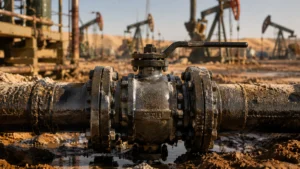
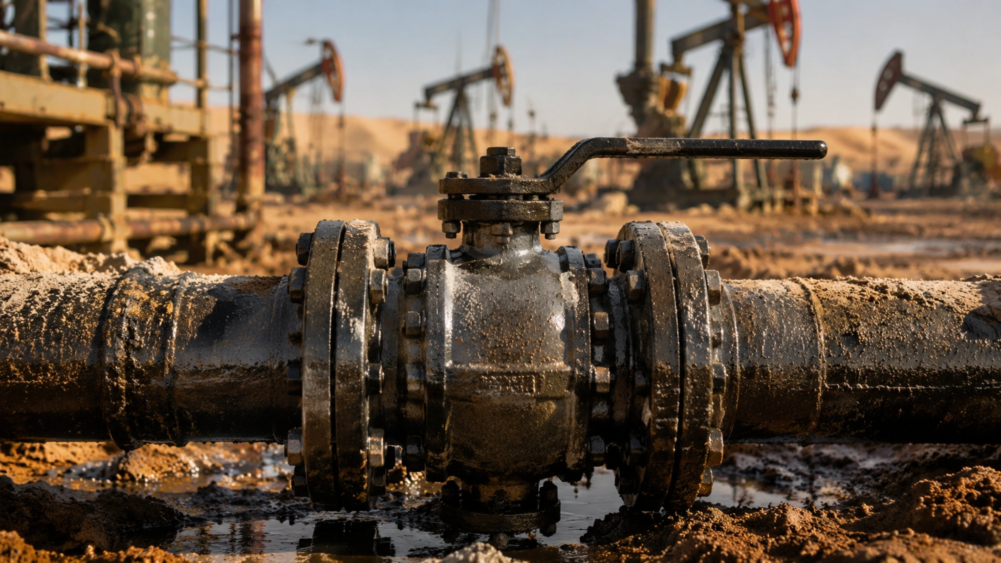
In oil production with sand-laden fluids, seal-face wear on ball valves is a common cause of internal leakage, torque increase, and unplanned valve replacement. Practical protection normally combines sand-severity screening, velocity control, wear-resistant sealing surfaces, debris-control seat geometry, and inspection intervals based on measured wear history.
In one Middle East oilfield project, produced fluid entering the valve package intermittently contained 0.8%–1.2% sand by volume during sand-upset periods before final sand-control improvement. The uncoated stainless-steel seat set was replaced 3 times in 12 months, and each replacement cost around USD 28,000 including parts, field labor, and pressure testing.
The field values in this article are project screening values from reviewed sand-laden service cases. They are not universal design limits from API 6D, ISO 17292, API 598, or any other valve product or test standard. For formal oil and gas sand-management and erosion-assessment work, DNV-RP-O501 provides a dedicated recommended-practice framework for managing sand production and erosion through design and operation of production facilities.[1]
Erosion Mechanisms
How Much Sand Is Considered Severe
Solid particles in produced fluids can damage the ball, seat, coating layer, and nearby flow passages. The damage rate depends on particle hardness, particle size, particle shape, concentration, velocity, impact angle, fluid phase, pressure drop, valve geometry, and cycling frequency.
API Specification 6D is a valve specification used internationally to define manufacturing requirements for valves. It should not be interpreted as a sand-content limit or maintenance-interval standard for metal-seated ball valves in dirty production service.[2]
| Sand Content by Volume | Observed Valve Performance in Reviewed Cases | Practical Response |
|---|---|---|
| 0.3%–0.5% | Metal-seated valves with suitable seat material or coating commonly reached approximately 18–24 months when velocity and cycling were controlled. | Review velocity, particle size, cycling frequency, seat material, coating requirements, and pressure drop across the valve. |
| 0.5%–0.8% | Wear risk increased clearly, especially where pressure drop or local jetting occurred near the seat. | Use hard-coated or hardfaced seat-and-ball pairs and verify operating velocity. |
| 0.8%–1.0% | Uncoated stainless-steel seats in the reviewed cases often fell to 3–5 months. Upgraded metal-seated configurations with carbide coating or cobalt-based hardfacing sometimes reached 6–8 months before repair. | Use a more aggressive erosion-control strategy from the start, including upstream sand removal and early inspection. |
| Above 1.0% | Service conditions were extremely severe and highly sensitive to flow velocity, particle size, pressure drop, and valve cycling. | Use high-performance wear-resistant coatings, carbide-alloy seat pairs, upstream sand-removal equipment, and condition-based inspection. |
ISO 17292 specifies requirements for metal ball valves used in petroleum, petrochemical, natural gas plants, and related industrial applications. It should not be read as a service-life ranking standard for sand-laden production fluids.[3]
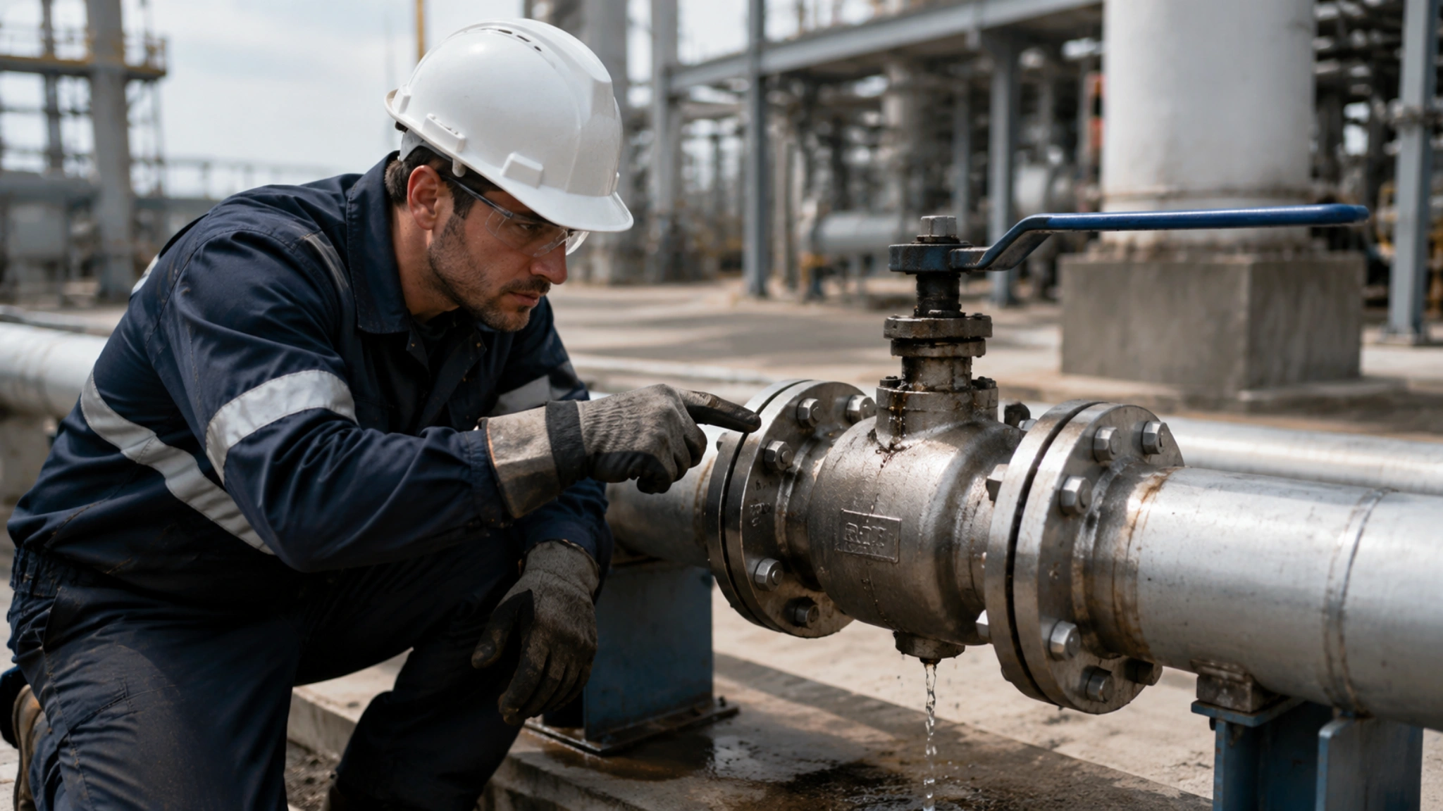
A practical field method for assessing sand severity is to inspect groove depth on the seat seal face during teardown. The following limits were used as project inspection criteria, not as universal acceptance limits.
| Observed Groove Depth on Seat Seal Face | Condition in Reviewed Failed-Seat Batches |
|---|---|
| 0.1–0.3 mm | The seal faces were usually repairable by controlled lapping, polishing, or re-coating, depending on remaining coating thickness and substrate condition. |
| Above 0.3 mm | The valves commonly showed through-seat internal leakage or could no longer meet the specified closure-test acceptance criterion. |
How Much Flow Velocity Affects Erosion
Flow velocity is one of the most important variables in solid-particle erosion.
Solid-particle erosion often increases nonlinearly with particle impact velocity. ASTM G76 is a laboratory method for measuring material loss from gas-entrained solid-particle impingement. It is useful for ranking erosion resistance under specified test conditions, but it also states that actual service may vary widely in particle size, velocity, attack angle, environment, and other factors; therefore, one laboratory test alone is not enough to predict field performance.[4]
The API RP 14E erosional-velocity equation is a screening tool for production piping, not a valve-specific seal-face wear equation. Published reviews have noted that API RP 14E does not adequately account for several factors that strongly affect erosion, including material properties, flow geometry, flow regime, sand production rate, and corrosive species.[5]
| Field Parameter | Lower-Velocity Condition | Higher-Velocity Condition |
|---|---|---|
| Sand content | 0.6% | 0.6% |
| Flow velocity | 3 m/s | 6 m/s |
| Monthly seal-face wear | 0.02 mm | 0.09 mm |
| Measured increase | Baseline | 4.5× |
The wear data above came from a reviewed field comparison under the same sand-content category. It should not be converted into a universal erosion formula because valve size, trim geometry, pressure drop, particle distribution, and fluid phase can change the result significantly.
For the reviewed sand-laden projects, the following working velocity limits were used as engineering controls. They should be adjusted after checking particle size distribution, pressure drop, valve size, valve bore geometry, and fluid phase.
| Sand Content by Volume | Project Working Velocity Limit |
|---|---|
| 0.3%–0.5% | 4.5 m/s |
| 0.5%–1.0% | 3.0 m/s |
In one Canadian oil sands project, a Class 600 ball valve developed severe internal leakage after only 4 months when velocity was not controlled. After the valves were upgraded with tungsten-carbide-coated seats and operating velocity was reduced from 5.5 m/s to 3.2 m/s, metal-seated valve life increased to more than 14 months in the same service envelope.
- Valve groups cycled 5 times/day were used as the lower-frequency comparison.
- Valve groups cycled 20 times/day showed approximately 60% faster seal-face wear.
- Unnecessary open-close cycles should be minimized in sand-laden pipelines.
The Seat Fails First
In sand-laden service, the seat seal face is often the first ball-valve component to lose sealing function.
| Inspection Finding | Observed Result |
|---|---|
| Failed valves inspected | More than 40 |
| Failures attributed mainly to seat seal-face erosion | More than 85% |
| Other common damage | Ball-surface scoring and stem-packing wear |
| Uncoated stainless-steel seats at about 0.8% sand | 3–5 months of measured service life |
| WC-sprayed or Stellite-hardfaced seats under comparable reviewed conditions | 12–24 months of measured service life |
Seat failure is promoted by concentrated sealing pressure. When the valve closes, hard particles can become trapped between the ball and the seat and act as a grinding layer. In one water-injection project using sand-laden produced fluid, visible grooves appeared on the pressure-side seat face within 2 months while the stem and packing box on the same valve remained serviceable.
If sand content is expected to exceed 0.3% by volume, a seat-and-ball material solution suitable for abrasive service should be specified during valve selection rather than added only after failure.
Hard Coating Treatments
Tungsten Carbide Spray Coating
Tungsten carbide thermal spray is one of the most widely used surface-hardening technologies for ball valves in sand-laden service. WC–10Co–4Cr is commonly selected where both abrasive wear resistance and better corrosion behavior than plain WC–Co are required.
| WC–10Co–4Cr HVOF Coating Property | Typical Qualified Range |
|---|---|
| Hardness | HV0.3 1000–1400 |
| Bond strength on steel | Above 80 MPa |
| Typical finished coating thickness for reviewed valve seats and balls | 0.15–0.30 mm |
Höganäs technical data for HVOF-sprayed WC 10Co 4Cr lists bond strength on steel above 80 MPa and hardness of HV0.3 1000–1400. It also notes that coating performance depends on powder grade, process, parameters, coating quality, microstructure, phase composition, and substrate material.[6]
In a condensate gas field project, stainless-steel seats were replaced with WC–10Co–4Cr HVOF-coated seats. After 18 months at about 0.5% sand content, measured coating loss on the inspected sealing surface was 0.08 mm, leaving enough coating thickness for continued service after inspection and polishing.
Post-coating sealing treatment can be important when connected micro-pores or process defects allow corrosive fluid to reach the coating interface. In one batch of WC-coated seats, unsealed pores allowed acidic drilling-fluid components to attack the interface and caused local delamination. Applying a low-viscosity sealer improved measured corrosion resistance in that project by approximately 30%–50%.
The ball surface can be coated with the same process, but finished coating thickness should be controlled tightly to protect roundness, sealing geometry, and final dimensional tolerance. In the batches reviewed, forged substrates gave more consistent bond-strength results than comparable cast substrates after the same surface preparation and spray procedure.
HVOF Process
High-Velocity Oxygen Fuel spraying uses combustion to accelerate coating powder toward the prepared substrate. Oerlikon Metco describes typical HVOF particle velocity as 400–800 m/s and states that HVOF can create dense, tightly adherent coating layers with high hardness, wear resistance, and corrosion resistance.[7]
Well-optimized HVOF WC coatings can reach very low porosity. In abrasive service, this matters because connected porosity and unmelted-particle defects can become paths for under-film corrosion and coating spallation.
In sand-laden comparative tests from reviewed projects, HVOF–WC coatings showed about one-third the erosion weight loss of plasma-sprayed Al₂O₃–TiO₂ coatings under the same test conditions. An oil sands project using HVOF-refurbished 12-inch ball valves achieved more than twice the wear life of the original plasma-sprayed valves.
HVOF process parameters strongly affect coating quality. In cases reviewed, oxygen-flow deviation of more than 5% increased measured porosity from about 0.5% to 1.8% and reduced wear resistance. The following values were the qualified window for one kerosene-fueled HVOF system and should not be treated as universal settings for every HVOF gun.
| Process Parameter | Qualified Range in Reviewed Kerosene-HVOF Cases |
|---|---|
| Kerosene flow | 22–26 L/h |
| Oxygen flow | 850–950 L/min |
| Spray distance | 350–400 mm |
| Post-coating seal-face finish | Ra ≤ 0.4 μm |
Excessive seal-face roughness accelerates wear on the mating surface. For ball-valve sealing pairs, coating qualification should include bond strength, hardness, porosity, final roughness, coating thickness, dimensional inspection, and a closure test after final lapping or polishing.
Stellite Hardfacing
Stellite 6 cobalt-based alloy hardfacing is a long-proven option for metal valve seats where wear resistance, galling resistance, corrosion resistance, and high-temperature capability are required.
| Stellite 6 Property | Typical Value |
|---|---|
| Cobalt | Balance |
| Chromium | 27%–32% |
| Tungsten | 3%–6% |
| Carbon | 0.9%–1.4% |
| Hardness | HRC 36–45 / HV 380–490 |
| High-temperature wear performance | Retains a reasonable level of hardness up to about 500°C |
Kennametal Stellite lists Stellite 6 with Co balance, Cr 27%–32%, W 3%–6%, C 0.9%–1.4%, hardness of HRC 36–45 / HV 380–490, and retained useful hardness up to about 500°C. It also lists valve seats and gates among typical hardfacing applications.[8]
In one reviewed thermal heavy-oil project with sand, Stellite 6 hardfaced seats operated for more than 36 months without replacement at 0.4%–0.6% sand and about 250°C. Stellite hardfacing is particularly suitable where both wear resistance and elevated temperature are important.
Weld-bead overlap and dilution rate are key hardfacing controls.
- Target Stellite hardfacing thickness: 1.5–3.0 mm.
- Target dilution in reviewed PTA cases: below 10%.
- Observed failed batch: 22% dilution, HRC 30 surface hardness, and localized edge collapse after 6 months.
- Observed PTA dilution range in acceptable batches: 5%–8%.
Plasma Transferred Arc welding was selected in the reviewed valve-seat applications because it helped control dilution more consistently than manual hardfacing, especially on small or narrow sealing surfaces.
For sand-laden thermal-recovery projects using metal-seated ball valves, Stellite 6 hardfaced seats are often preferred for sustained high-temperature service. WC–CoCr coating limits should be set by the qualified coating procedure, binder chemistry, atmosphere, coating quality, and owner-approved service-temperature envelope.
Design Protection
Sand Scraper Structure
A sand scraper, or wiping ring, is a mechanical barrier installed near the ball-seat interface. Its purpose is to remove loose particles from the ball surface during opening and closing and to reduce the amount of debris entering the seal-face gap.
Scraper-equipped valves lasted roughly 3× longer than unprotected valves in one Middle East water-injection project under the same operating envelope. This result should be treated as a project outcome, not a universal multiplication factor.
- Scraper rings are normally made from materials softer than the coated ball, such as bronze, graphite, or PTFE-based composites.
- The softer scraper material helps reduce the risk of scratching the ball surface.
- One reviewed design used a combined PTFE and stainless-steel mesh scraper ring at the seat front.
- The stainless-steel mesh provided mechanical strength, while PTFE provided low-friction wiping behavior.
- The scraper remained functional after 5,000 continuous open-close cycles in the project endurance check.
- The design was used for produced fluid containing about 0.3%–1.0% sand by volume.
Scraper rings are intended to prevent solid particles from wedging between the ball and the seats, which can cause blocking, scoring, and seal leakage. Penta Valve describes this as a key function of scraper rings in metal-seated ball valves.[9]
From a structural perspective, trunnion-mounted ball valves are usually easier to protect with scraper features than floating ball valves in abrasive service. The trunnion-supported ball follows a more stable movement path, making scraper clearance easier to control.
Scraper Seat Design
A scraper seat has a small raised scraping lip machined onto or near the metal seat seal face. During valve closing, the lip removes deposited sand and debris from the ball surface before the final sealing load is reached.
Unlike a passive scraper ring, a scraper seat creates a self-cleaning action through the seat geometry. Crane’s Krombach TUFSEAT technical literature describes seat geometry that creates a scraper self-cleaning effect and shows standard scraper designs for abrasive and viscous services.[10]
In one forged metal-seated ball-valve evaluation, scraper seats were tested in a sand-laden produced-fluid pipeline. After 3,000 operating cycles at about 0.7% sand content, the valve still met the specified API 598 closure-test acceptance criterion. “Class VI” should not be described as an API 598 leakage class; Class VI is an ANSI/FCI 70-2 control-valve leakage classification.[11][12]
| Scraper-Seat Parameter | Project Recommendation |
|---|---|
| Scraper-lip height | 0.3–0.5 mm |
| Scraper-lip angle | 45°–60° |
| Preferred ball surface | HVOF tungsten carbide coating |
| Poor-design warning | Edges above 1 mm scratched the ball and accelerated failure in one failed design review. |
Scraper seats are normally paired with metal sealing. Soft-seated valves can use upstream scraping or debris-control features only in low-sand service because aggressive scraping action can tear, cut, or extrude soft sealing materials.
Scraper seats remove loose or attached particles, but they have limited ability to remove hard particles embedded into the coating or seat surface. They should therefore be used together with upstream filtration or sand-removal equipment. In one project, desander efficiency fell from 95% to 82%, and the scraper-seat maintenance interval shortened from 12 months to 7 months.
How to Determine Maintenance Intervals
Maintenance intervals in sand-laden service should be based on operating conditions and inspection history, not on a fixed calendar rule alone.
API 6D does not prescribe a universal 12-month maintenance interval for sand-laden valves. In the reviewed projects, 12 months was used only as a starting interval in a field correction model.
Recommended interval = base interval × sand correction factor × velocity correction factor
| Operating Condition | Correction Factor |
|---|---|
| Sand content of 0.3%–0.5% | 0.8 |
| Sand content of 0.5%–1.0% | 0.5 |
| Velocity above 4.5 m/s when sand is 0.3%–0.5% | Multiply by an additional 0.7 |
| Velocity above 3.0 m/s when sand is 0.5%–1.0% | Multiply by an additional 0.7 |
For a condensate gas field project with 0.6% sand and 2.8 m/s velocity, the resulting starting interval was 6 months:
12 months × 0.5 = 6 months
For the same 0.6% sand service at 4.0 m/s, the velocity correction should be applied because the velocity exceeds the 3.0 m/s project limit for 0.5%–1.0% sand service:
12 months × 0.5 × 0.7 = 4.2 months
During a sixth-month teardown in the lower-velocity case, the seat seal face had a 0.15 mm groove, which remained within the project-specific repairable range.
Another maintenance method is condition-based wear monitoring.
- On an offshore platform project, monthly ultrasonic thickness measurements were taken at an accessible designated wear-monitoring location near the seat area.
- When the measured wear rate exceeded 0.03 mm/month, maintenance was scheduled early.
- The project operated for 24 consecutive months without an unplanned shutdown caused by seat-area wear-through.
- Compared with fixed-interval maintenance, unnecessary teardowns were reduced by approximately 40%.
The correction factors should be adjusted using actual operating records. If the first teardown shows groove depth below 0.1 mm and no coating delamination, the sand correction factor can be relaxed for the next interval. If groove depth exceeds 0.3 mm, the interval should be shortened and the seat material, coating thickness, scraper design, and upstream sand-removal performance should be reviewed.
Protecting ball valves in sand-laden service requires a coordinated engineering approach: identify erosion severity, limit velocity, select a qualified hard coating or hardfacing process, add scraper or self-cleaning seat features where appropriate, and set maintenance intervals from measured wear. In the reviewed field cases, combining WC–HVOF coating, scraper-seat geometry, velocity control, and a 4–6 month initial inspection cycle increased average service life in 0.5%–1.0% sand service from about 8 months to more than 24 months. In the same cases, estimated per-valve lifecycle cost fell by approximately 55% after including seat replacement cost, coating upgrade cost, field maintenance labor, and avoided repeat teardown cost. Production-loss assumptions were not included in that 55% estimate.


")