
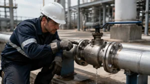
Ball valves are widely used shut-off devices in oil and gas, petrochemical, chemical processing, water treatment, and industrial pipeline systems. When leakage appears in the field, the first step is not to replace parts immediately. The first step is to identify the actual leak path.
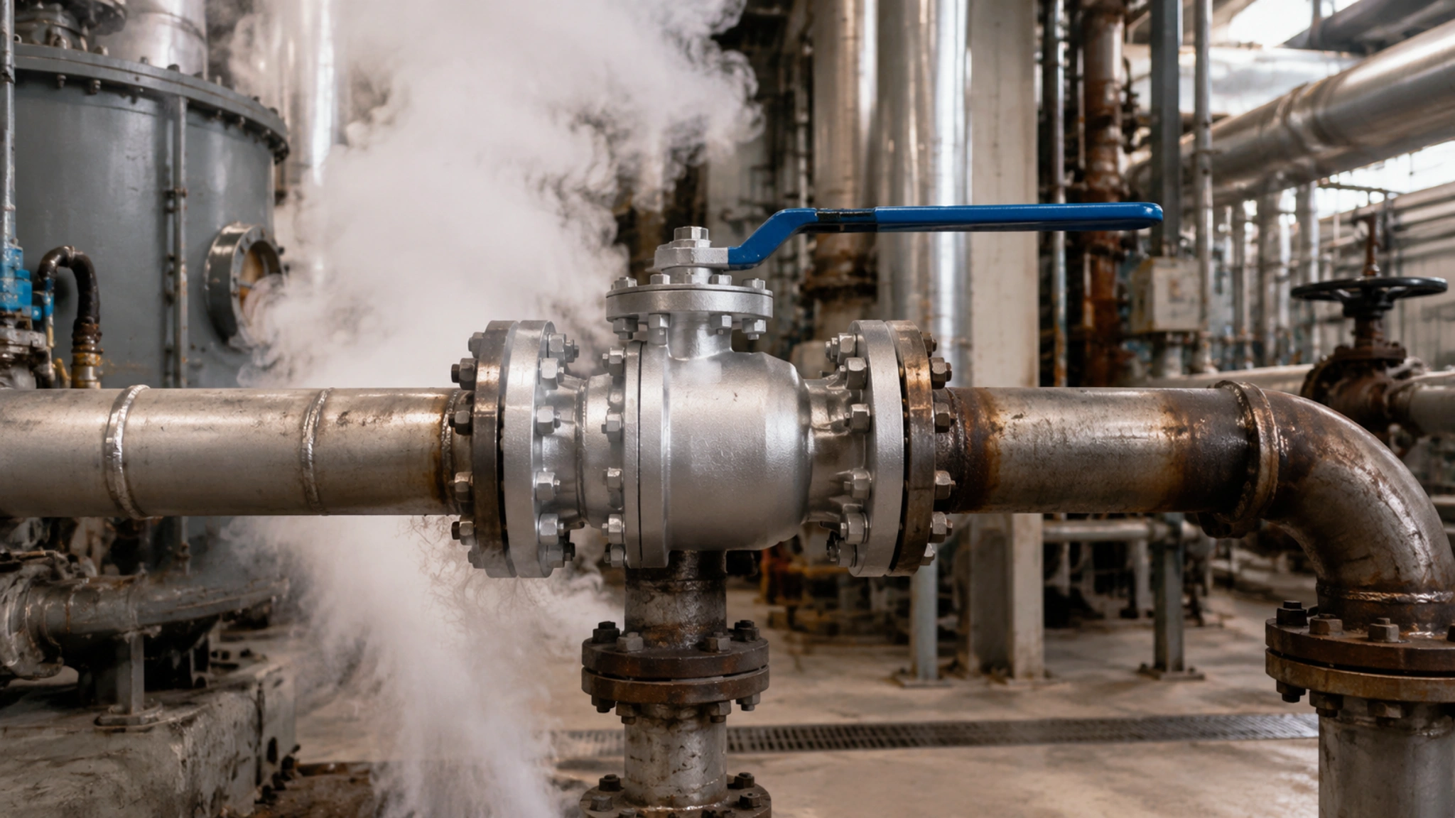
Most ball valve leakage problems can be separated into two broad categories: external leakage and internal seat leakage. External leakage includes stem packing leakage and flange joint leakage. Internal leakage usually means the valve fails to hold pressure when fully closed.
API 6D ball valves should be diagnosed in a clear field sequence: identify the leak path first, then select the corrective action. API 6D defines requirements for the design, manufacturing, assembly, testing, and documentation of ball, check, gate, and plug valves for pipeline and piping systems in the petroleum and natural gas industries.[1]
Many valve leakage problems in service are linked to installation conditions, thermal cycling, process contamination, incorrect operation, actuator adjustment, or maintenance practices. The valve body itself should not be blamed until the leak point is confirmed.
Minor checks such as visual inspection, packing observation, flange joint inspection, and downstream leakage confirmation can often be performed with basic field tools. Repairs involving pressure-containing parts, seat refacing, oxygen service, hydrogen service, sour gas, toxic media, or flammable media must follow the valve manufacturer’s manual and the site’s approved safety procedure.
| Leak Scenario | Typical Leak Location | Key Field Sign | First Corrective Action |
|---|---|---|---|
| Stem leak | Around the stem and packing chamber | Leak remains at the stem area even when the valve is closed | Check packing gland preload, packing condition, stem surface, and secondary seal condition |
| Pipeline flange joint leak | Valve end flange or mating pipeline flange | External leak appears at the flange gap and is usually less dependent on ball position | Check gasket condition, flange alignment, bolt load, and tightening sequence |
| Valve not holding when closed | Ball-to-seat sealing interface | Downstream leakage appears after full closure | Check seat damage, particle jamming, actuator stop setting, seal wear, or thermal distortion |
Locating the Leak Source
Stem Leak
A stem leak occurs when process medium escapes through the sealing area around the valve stem and packing chamber. For a quarter-turn ball valve, the stem rotates during operation. The packing must seal the stem while still allowing controlled movement.
Industrial valve troubleshooting guidance commonly separates valve leakage into seat leakage and shell leakage. Seat leakage means fluid passes through the internal closure mechanism. Shell leakage means fluid leaks outside the valve body into the atmosphere, often through the stem or body area.[2]
- Leakage is concentrated around the stem penetration, packing gland, or bonnet area.
- Medium visibly drips, seeps, bubbles, or leaves residue around the stem.
- The leak remains at the stem area after the valve is fully closed.
The last point is the key difference from seat leakage. If the valve is fully closed but leakage continues from the stem area, the leak path is external and related to the stem sealing system.
Typical root causes include insufficient packing gland preload, aged packing rings, thermal cycling, packing extrusion, stem scratches, corrosion on the stem surface, chemical attack, or a damaged O-ring or secondary seal.
In one DN50 Class 150 floating ball valve field case, the valve had been dripping from the stem for a long period before maintenance support was requested. After disassembly, the PTFE packing rings had hardened and shrunk, leaving a small gap in the stuffing box.
After the full packing set was replaced and the gland was tightened according to the manufacturer’s maintenance sheet, no visible leakage was observed during the field check. If the leak is caught early, small and even packing adjustment may stop minor seepage without full disassembly.
Do not tighten the packing gland aggressively. Excessive gland load can increase operating torque, damage the packing, score the stem, or make the valve difficult to operate.
Pipeline Flange Joint Leak
A pipeline flange joint leak occurs when process medium escapes from the sealing interface between the valve end flange and the mating pipeline flange. It usually appears at either the upstream or downstream flange connection.
This should not be confused with a valve body joint leak. In many valve documents, “body flange” may refer to a valve body-cover joint rather than the pipe-end flange connection. For this reason, “pipeline flange joint leak” or “valve end-flange joint leak” is more accurate when the leakage is at the pipe connection.
In most cases, a flange joint leak is less dependent on ball position than seat leakage because the leak path is outside the ball-to-seat sealing interface. However, the leak rate can still change if the downstream side is depressurized or if pressure distribution changes after the valve is closed.
ASME PCC-1 provides guidelines for pressure-boundary bolted flange joint assembly. It applies to pressure-boundary flanged joints with ring-type gaskets and is commonly used to develop effective flange assembly procedures for industrial pressure systems.[3]
- Scratched, corroded, or contaminated flange faces can prevent proper gasket seating.
- Wrong gasket type, wrong gasket size, or excessive compression can cause early gasket failure.
- Uneven bolt preload can come from poor alignment, non-cross-pattern tightening, unlubricated bolts, or uncalibrated torque tools.
- Thermal cycling and gasket relaxation can reduce bolt load after installation.
Garlock’s metallic gasket installation guidance emphasizes correct bolting pattern, calibrated torque tools, and applicable safety procedures. It also warns against retightening a flange connection once it has been brought up to temperature or pressure.[4]
In one DN80 PN40 chemical plant case, leakage appeared at the lower flange gap after several thermal cycles during unit startup. The gasket had likely experienced stress relaxation and reduced sealing stress.
The flange bolts were retightened only after the section was made safe, using a calibrated torque wrench, the site-approved torque table, and a cross-pattern sequence. The leak stopped without replacing the gasket. The torque value used in that case should be treated only as a site-specific maintenance value, not as a universal torque recommendation.
Pipeline flange joint leaks are sometimes misidentified as valve body casting cracks. Confirm the actual leak path before authorizing valve replacement.
Valve Not Holding When Closed
A valve that continues to pass fluid when fully closed indicates internal seat leakage. This is fundamentally different from stem leakage or flange leakage.
In clean service, many PTFE, RPTFE, PEEK, or other soft-seated ball valves can provide very tight shutoff. In dirty service, the effective seat life can drop sharply because solids can scratch, embed into, or deform the seat sealing surface.
Soft seats usually provide better tight shutoff in clean service, while metal-seated valves are more suitable for many high-temperature, abrasive, erosive, or severe-service conditions. Valmet’s metal-seated ball valve literature describes application-based seat selection for demanding applications, including abrasive fluids.[5]
- Close the valve fully using the correct operating method.
- Confirm that the actuator or hand lever has reached the correct closed stop.
- Monitor the downstream test port, drain point, pressure gauge, or sight glass.
- If leakage continues from the downstream side, suspect the ball-to-seat sealing interface.
Common field causes include damaged seat inserts, particles trapped between the ball and seat, fractured or hardened seat O-rings, incorrect actuator stop setting, seat wear, ball coating damage, or thermal distortion.
In one seawater service case, marine debris lodged in the soft seat face after a storm event. After disassembly and compatible cleaning of the sealing surfaces, the valve passed the specified nitrogen test with no visible leakage during the required test period.
Seat leakage should be inspected before ordering expensive seat kits. When the seat is contaminated but not permanently damaged, cleaning and reassembly may restore sealing performance.
Stem Leakage Repair
Tightening the Packing Gland
The packing gland applies controlled axial compression to the packing rings inside the stuffing box. This compression helps the packing expand radially against the stem and stuffing box wall to form a dynamic seal.
Insufficient packing preload is a common cause of stem leakage. Packing adjustment may restore leak-tight performance in some valves, but the adjustment must be performed in small increments and according to the valve manufacturer’s instructions.
Swagelok packing adjustment instructions for certain ball valve series specify small incremental adjustment and warn against readjusting packing without depressurizing the valve as required by the instructions.[6]
Packing relaxation is especially common after thermal cycling, vibration, repeated operation, or long service exposure. The original assembly load may reduce over time.
- Inspect the stem area for seepage, corrosion, process residue, or packing extrusion.
- Confirm whether the valve design allows packing adjustment while installed.
- Use only the manufacturer’s torque value or turn-count instruction.
- Stop tightening if the valve becomes hard to operate or if leakage does not improve after controlled adjustment.
- Confirm that the valve section is isolated, depressurized, drained, and locked out according to site procedure.
- Check the valve manufacturer’s manual for the permitted packing adjustment method.
- Loosen locking parts only if required by the procedure.
- Tighten the gland nuts or packing bolts evenly in small increments.
- Use a calibrated torque wrench if a torque value is provided.
- Operate the valve through the permitted range and check for abnormal torque or binding.
- Observe the stem area during the specified inspection period.
- If leakage persists, stop adjustment and plan packing replacement.
For a small Class 150 DN50 valve, packing gland torque may fall in a low double-digit N·m range in some designs. However, the actual value depends on stem size, packing material, gland design, bolt size, lubrication, temperature, pressure class, and manufacturer data. It should never be treated as a universal value.
A common field mistake is tightening one side of the gland fully before touching the opposite side. This can tilt the gland, create uneven packing compression, increase stem friction, and make the leak worse.
O-Ring Replacement Procedure
O-rings are radial sealing elements used in many valve stem, body, seat, and auxiliary sealing locations. Their exact function and position depend on the valve design.
Common elastomeric O-ring materials include FKM, NBR, EPDM, HNBR, and FFKM, depending on temperature, pressure, media, and emission requirements. PTFE is more commonly used as packing, backup rings, seat inserts, or engineered seal components rather than as a conventional elastic O-ring.
Parker’s O-Ring Handbook is a widely used reference for O-ring design, material selection, elastomer properties, extrusion control, and installation considerations.[7]
- Hardening and loss of elasticity indicate aging or thermal damage.
- Permanent flattening of the cross-section indicates compression set.
- Cracks, swelling, tackiness, or crazing indicate chemical incompatibility or material degradation.
- Cuts or spiral marks may indicate installation damage.
Viton FKM materials are widely used for heat and chemical resistance. Viton technical literature describes operating temperature capability around 149–204°C in selected applications, depending on grade and service condition.[8]
PTFE has excellent chemical resistance and low friction. Daikin’s POLYFLON PTFE F-Series product information lists heat resistance at a continuous operating temperature of 260°C and inertness to almost all chemicals.[9]
| Seal Material | Common Temperature Reference | Field Note |
|---|---|---|
| FKM / Viton | Often used around 149–204°C, depending on compound and service condition | Good heat and chemical resistance, but compatibility must be verified for the actual media |
| PTFE | Commonly referenced up to about 260°C in suitable applications | Excellent chemical resistance and low friction, but limited elastic recovery compared with elastomers |
| NBR | Moderate-temperature oil and water service, depending on compound | Not suitable for all solvents, ozone, or high-temperature service |
| EPDM | Water, steam, and some chemical service, depending on compound | Generally not suitable for petroleum oils and hydrocarbon service |
| FFKM | High-performance chemical and high-temperature service | Excellent resistance but high cost; use where service severity justifies it |
- Fully isolate and depressurize the valve section.
- Drain and purge residual process fluid according to the site safety procedure.
- Remove the gland follower, retainer, or related stem sealing parts according to the valve manual.
- Extract the old O-ring using a non-marring tool.
- Record the O-ring inner diameter, outer diameter, cross-section, material marking, and hardness if available.
- Inspect the groove for scratches, corrosion pits, burrs, or deposits.
- Clean the groove with a compatible cleaner.
- Apply only a lubricant compatible with the O-ring material, process media, oxygen requirement if applicable, and temperature condition.
- Install the new O-ring by hand without twisting, overstretching, or cutting it.
- Reassemble and test according to the manufacturer’s procedure.
Installing the wrong elastomer in steam, amine, sour gas, solvent, oxidizing chemical, oxygen, or high-temperature service can cause rapid failure. Material compatibility verification should be completed before any seal is installed.
Graphite Packing Refill
Graphite packing offers better high-temperature capability than PTFE in many steam, hot oil, refining, and high-temperature hydrocarbon services. Flexible graphite packing is commonly used where temperature, pressure, and emission requirements exceed the practical limits of many polymer packing materials.
Teadit describes its flexible graphite packing as heat resistant, chemically inert, low friction, self-lubricating, and readily conformable.[10]
- Fully depressurize, drain, and isolate the valve.
- Remove the gland nuts and lift off the gland or gland follower.
- Use a dedicated packing extraction tool whenever possible.
- Avoid scratching the stem or stuffing box.
- Remove all old packing rings and clean the stuffing box completely.
- Cut or select new graphite packing rings to the correct cross-section and length.
- Install the rings one by one according to the manufacturer’s arrangement.
- Stagger the butt joints of adjacent rings, commonly by about 90 degrees unless the manufacturer specifies otherwise.
- Compress each ring before installing the next ring.
- Reinstall the gland and tighten evenly to the approved torque or turn-count procedure.
In oxygen service, the key safety issue is cleanliness and lubricant compatibility. Do not use ordinary hydrocarbon-based lubricants in oxygen-rich environments unless the lubricant is specifically approved for that oxygen service.
CGA G-4.1 provides guidance for cleaning equipment used in oxygen service. It states that oxygen equipment must be cleaned to remove harmful contamination, including oils, greases, solvents, weld slag, rust, sand, dirt, and other organic or inorganic materials before oxygen is introduced.[11]
Seat Leakage Repair
Scratched Sealing Surface
The seat sealing face is the precision interface between the ball surface and the seat ring. It is critical for reliable shutoff.
Machined sealing surfaces may be finished in the Ra 0.8 to 1.6 micrometer range in many industrial applications, while hard metal-seated sealing surfaces may require a finer or project-specific finish. The exact value must follow the valve manufacturer’s drawing, repair procedure, or project specification.
API 598 covers inspection, examination, supplementary examination, and pressure test requirements for resilient-seated, nonmetallic-seated, and metal-to-metal seated valves, including ball valves. It defines closure testing as a pressure test used to confirm leakage past or through a valve’s closure mechanism.[12]
API 598 is a valve inspection and testing standard. API 6D valves may also be subject to API 6D-specific requirements and project specifications. For this reason, the purchase order, applicable standard edition, manufacturer manual, and project test procedure must be checked before applying any leakage acceptance criterion.
For resilient-seated valves, field writing should avoid the phrase “absolute zero leakage.” A more accurate phrase is “no visible leakage during the specified test duration under the specified test method.”
Solid particles and debris can pass between the ball and the seat during operation. These particles may leave radial scratches, embedded marks, or raised edges that create continuous internal leak paths.
- Close the valve.
- Drain and depressurize the cavity according to site procedure.
- Inspect the seat and ball sealing surfaces where accessible.
- Use a borescope, light inspection, or visual inspection when available.
- Run a clean, gloved fingertip gently across the sealing face only when safe and permitted.
- If a definite groove, burr, or raised edge is felt, the sealing surface is damaged.
- Perform a closure leak test according to the applicable standard or site procedure.
For shallow marks on metal-seated valves, controlled lapping may be possible if permitted by the valve manufacturer’s repair procedure. Soft PTFE, RPTFE, PEEK, nylon, or elastomeric seats should normally be replaced rather than hand-lapped because abrasive refacing can destroy the designed sealing geometry.
As a practical case, a shallow scratch on a forged metal-seated ball valve was hand-lapped under a controlled repair procedure. After cleaning and testing, no visible leakage was observed during the subsequent hydrostatic test.
Deep scratches, coating damage, loss of seat roundness, damaged contact geometry, or damage beyond the manufacturer’s repair limit requires professional repair, recoating, re-machining, or complete seat replacement.
Solid Particle Jamming
Solid particle jamming, also called particle interference, is a common cause of seat leakage in pipeline ball valves. It is especially common in multiphase flow, sand-laden crude oil, mineral slurry, seawater intake, dirty water, steam condensate with corrosion products, and industrial gas pipelines without adequate filtration.
When a hard particle becomes lodged between the ball and seat, it acts as a local high spot. This concentrates the sealing force onto one point and prevents the surrounding seal area from reaching the required contact pressure.
| Escalation Level | Field Action | Purpose |
|---|---|---|
| Level 1 | Cycle the valve fully open and fully closed three to five times, if the process condition allows | Use valve movement to dislodge or crush small particles |
| Level 2 | Open the valve fully and flush the seat area with compatible clean fluid | Clear loose particles from the seat gap and downstream side |
| Level 3 | Disassemble the valve and inspect the sealing surfaces | Confirm whether cleaning, lapping, or seat replacement is required |
In one crude oil production case, a quartz sand grain was lodged in a trunnion ball valve seat. Compatible flushing removed the particle, and the valve returned to no visible leakage during the specified field test.
For systems with chronic particulate contamination, consider upstream filtration, better flushing before commissioning, pigging improvements, harder seat materials, metal-seated designs, or severe-service trim. The final selection should account for temperature, pressure, shutoff requirement, media abrasiveness, torque, actuator sizing, and maintenance access.
In-Line Grinding Feasibility
In-line grinding, on-site milling, or field lapping uses purpose-designed portable tools to restore a metal seat sealing surface without removing the full valve body from the pipeline.
This method can reduce downtime in selected cases, but it is not a universal repair method. It should only be considered for suitable metal-seated or hard-faced sealing surfaces and only when allowed by the valve manufacturer or a certified repair procedure.
Valmet’s coating guidance for metal-seated ball valves explains that properly selected coatings help reduce friction between the ball and seats, improving sliding operation and reducing damage from galling, abrasion, erosion, particle impact, cavitation, and thermal swings.[13]
PTFE and RPTFE soft seats are too soft for abrasive refacing. Abrasive action can cut, smear, or deform the seal surface, so soft seats should normally be replaced rather than ground.
- Confirm the valve is metal-seated or otherwise approved for field lapping.
- Confirm there is enough clearance for the tool, operator, and inspection equipment.
- Confirm the pipeline section is fully depressurized, drained, purged, and physically isolated.
- Confirm the repair will not remove more material than allowed by the manufacturer’s repair limit.
- Confirm that post-repair testing can be performed before the valve is returned to service.
- Insert the approved tool through the accessible flange or bore opening.
- Secure the tool according to the tool manufacturer’s instructions.
- Use the abrasive grade specified in the repair procedure.
- Work progressively from coarser to finer abrasive only when required.
- Clean the sealing surface completely after each abrasive stage.
- Check contact pattern, surface finish, and seat geometry.
- Stop when the repair procedure’s surface finish and contact requirements are met.
- Perform closure testing according to the applicable standard, project specification, or manufacturer requirement.
Values such as 300 mm tool clearance, a 120 to 600 grit abrasive sequence, or Ra 0.8 to 1.0 micrometer finish may be practical examples for some tools and valve sizes. They should not be treated as universal requirements. The correct values depend on valve size, trim material, coating, seat geometry, tool design, and project specification.
In one refinery case, controlled seat lapping reduced the measured roughness of a metal-seated valve sealing surface and eliminated visible leakage during the post-repair test. The cost saving came from avoiding valve removal and transport, but the repair was acceptable only because the valve design and approved repair procedure allowed in-line work.
Field Diagnosis Checklist
| Observation | Likely Leak Type | What to Check First |
|---|---|---|
| Fluid appears around the stem | Stem packing or stem seal leak | Packing gland preload, packing condition, stem scratches, O-ring condition |
| Fluid appears between valve flange and pipe flange | Pipeline flange joint leak | Gasket condition, flange face damage, alignment, bolt load, torque sequence |
| Fluid passes downstream when the valve is fully closed | Seat leakage | Seat damage, ball damage, particles, actuator stop setting, seat wear |
| Leak appears after startup or heat-up | Thermal cycling or gasket relaxation issue | Gasket material, bolt load retention, flange joint assembly procedure |
| Leak appears after actuator installation | Possible actuator stop or stem loading issue | Open/close stop setting, stem alignment, actuator torque output, travel limit |
Gasket relaxation and thermal cycling can reduce bolt load after assembly. Teadit notes that bolted flange joints experience gasket relaxation after initial tightening and that retorque can be part of an installation process where permitted by the applicable safety and assembly procedure.[14]
Do not treat torque values in field examples as universal values. Flange bolt torque and gland torque depend on bolt size, bolt material, lubrication, gasket type, pressure class, valve design, temperature, and the manufacturer’s approved data.
When to Stop Field Repair
Minor stem seepage, loose packing preload, flange bolt relaxation, or removable particles may be handled in the field if the procedure is approved and the line is safe.
Stop field repair and escalate to the valve manufacturer or a certified valve repair shop if any of the following conditions apply:
- The valve body, bonnet, end connection, or pressure boundary is cracked.
- The leak involves toxic, flammable, oxygen, hydrogen, sour gas, or other high-risk media.
- The seat coating is damaged, cracked, peeling, or worn beyond the repair limit.
- The ball is deeply scratched, out of round, or coating-damaged.
- The valve fails the required closure test after cleaning or approved adjustment.
- The actuator may be forcing the valve beyond its travel stop or preventing full closure.
- The required torque value, repair limit, or test method is not available.
- The repair requires machining, welding, pressure-boundary modification, or coating restoration outside the approved field procedure.
Valmet ball valve maintenance instructions state that gland packing should be replaced if tightening does not stop leakage and that the valve must be unpressurized before packing replacement work is performed.[15]
Final Practical Rule
Start every ball valve leak diagnosis by identifying the leak path. Stem leakage, flange joint leakage, and seat leakage can look similar during a rushed field inspection, but they require different corrective actions.
If the leak is at the stem, check packing preload, packing condition, and stem seal condition. If the leak is at the flange joint, check gasket seating, flange alignment, and bolt load. If the valve passes fluid while fully closed, inspect the seat, ball surface, actuator travel, and process contamination.
Use API 6D, API 598, ASME PCC-1, manufacturer manuals, and project specifications as technical references. For any field repair, the valve manufacturer’s maintenance manual and the site safety procedure should take priority over general experience-based values.


")