
11 years in cryogenic valves, from -46°C carbon steel to -196°C LNG stainless steel. 90% of the selection pitfalls I see come from undersized bonnets or mismatched material grades. These 9 sections are my go-to client notes: 3 LNG scenarios, 3 standards, 3 material families.
LNG Site Needs
Storage Tank Lines
“Valves in the storage tank area look unremarkable, yet they are the only components in an LNG terminal that stay motionless year after year. The moment they move, something breaks.” — That was the senior operator pulling me aside at the tank bottom in 2019 when I was commissioning a 160,000 m³ LNG receiving terminal in Fujian.
Storage tank piping is the most moderate duty loop within the LNG terminal. Working pressure normally stays below 0.5 barg (nitrogen pad pressure), and the steady-state temperature sits near -162°C, but the boil-off gas (BOG) rate must remain under 0.05% per day in the long run. That means every single weld, every single valve, cannot leak beyond what is visible in a standard bubble test. The four major pipeline runs—tank inlet and outlet, bottom fill and draw, top BOG recovery, and recondenser circulation—must carry isolation valves and check valves that meet three conditions at the same time. First, body material impact energy ≥ 20J at -196°C (ASTM A370 requirement). Second, the seat must hit ISO 5208 Rate A zero-leakage. Third, the stem packing temperature must stay consistently above 0°C under operating conditions. The last two conditions alone knock roughly 60% of the products marketed as “cryogenic valves” off the procurement list.
- Tank inlet and outlet valves: Full-bore ball valves, body in CF3M or F316L, carbon content ≤ 0.03%
- BOG recovery line isolation valves: Reduced-bore ball valves are acceptable, CF8M is a viable body material, focus on seat wear under frequent cycling
- Recondenser circulation valves: Two-phase gas-liquid duty calls for a top-entry design so the seat can be serviced without breaking the pipe
- Tank bottom emergency shutdown valves (ESD): Independent gas supply or spring return, fail-close on signal loss, compliance with API 6D clause 25
From my experience across 6 storage terminals in China, the tank inlet valves that get replaced most frequently are not the bodies but the seats. Soft seats (PTFE) typically need replacement every 5 to 7 years even with proper operation, while hard seats (Stellite overlay) last 12 to 15 years but are not allowed below -101°C in LNG service. So the seat cycle is really a hidden OPEX item that the procurement team often forgets to budget for. When I draft a tank farm spec, I always add a 5-year seat replacement line item to the OPEX sheet so the client is not surprised mid-cycle.
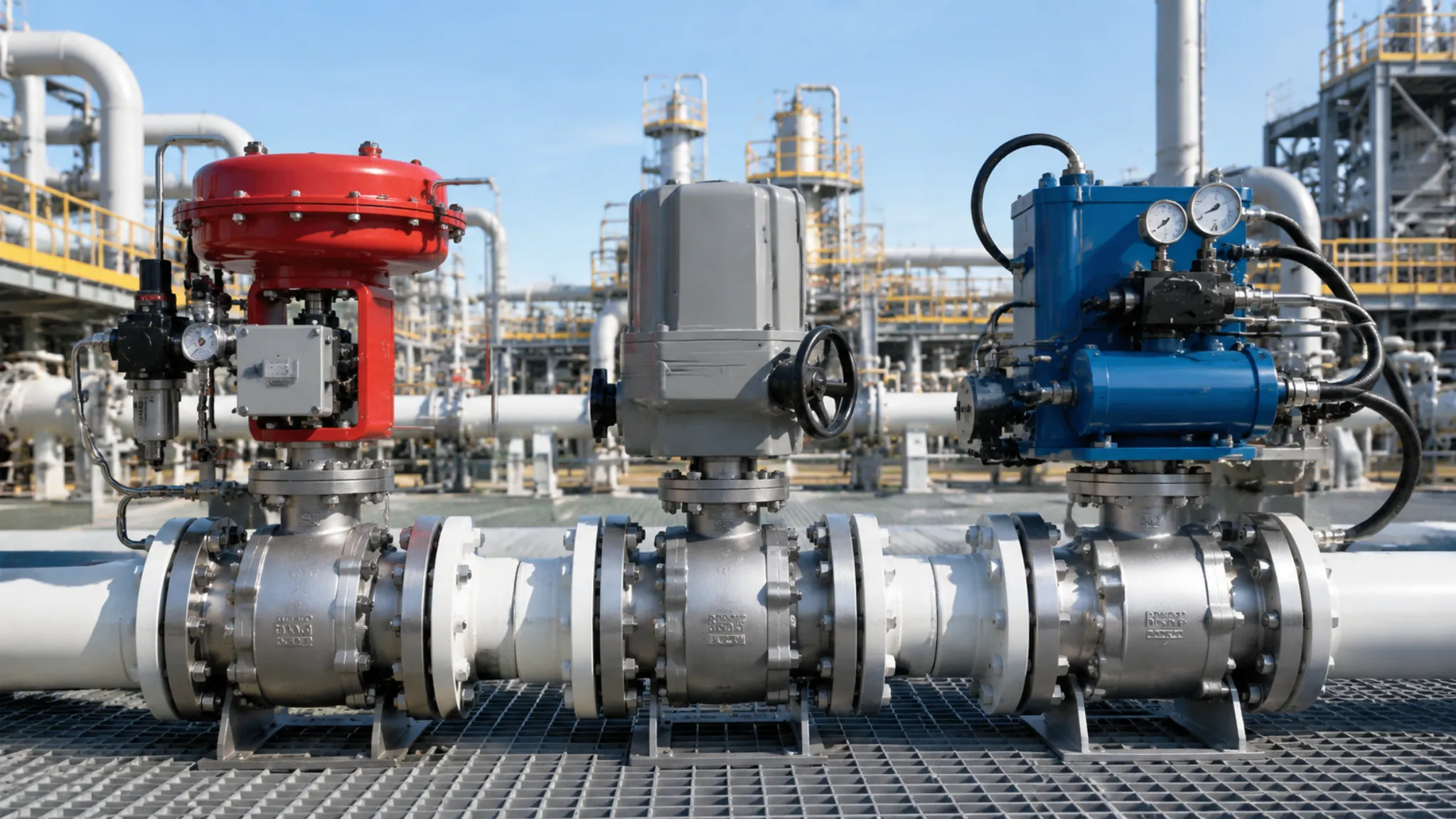
Loading Station Valves
The loading station is the harshest duty section in the LNG value chain. As tankers connect and disconnect, line pressure ramps from 0.5 barg up to 7 barg and back to zero, while the temperature repeatedly swings from -162°C through ambient, and each valve completes on average 800 to 1500 duty cycles per year. The loading arm root valve, the emergency release coupling (ERC), the return valve, the vent valve, and the tanker bottom fill valve each have their own distinct failure consequence, so the selection logic diverges sharply from that of storage tank valves.
- Loading arm root ball valve: Full-bore soft seat (PTFE or reinforced PCTFE), Class 300 is sufficient, but the long extended bonnet (200 to 500 mm adjustable range) is mandatory to prevent packing glass transition failure under LNG immersion
- Tanker bottom fill valve: Must be paired with an independent pneumatic actuator plus spring return, fail-close on signal loss, dual compliance with ADR (European Agreement concerning the International Carriage of Dangerous Goods by Road) and DOT 49 CFR §173.318 (US LNG tanker mandatory clause)
- Return valve (circulation line): Used to push residual LNG back to the tank, Class 150 is acceptable, but seat cycle life must be ≥ 5000 cycles (far above the API 6D default of 1000 cycles)
- Emergency release coupling (ERC): Cuts off and seals both pipe ends within 0.5 seconds during accidental arm pull-away, trip pressure typically set between 4.5 and 6 barg, must be certified to EN 1474-3 (LNG loading and unloading equipment dedicated standard)
One common mistake I see in tender documents is specifying Class 600 or Class 900 for loading station valves when Class 300 is technically adequate. The higher class adds cost in terms of body mass (about 35% heavier at Class 600 vs Class 300 in the same size) and longer lead time, with no functional benefit at 7 barg working pressure. Make sure the procurement team is aligned on the actual pressure class needed before issuing the RFQ, otherwise the supplier will quote the high side and the EPC will be locked in for the project life. In my last 4 loading station jobs the correct class was 300, not 600, and the saved mass per valve averaged 180 kg.
Regasification Plants
Regasification plants are the highest pressure segment in the LNG value chain. LNG coming out of open-rack vaporizers (ORV) or submerged-combustion vaporizers (SCV) is still in a saturated -162°C liquid-full state, and the high-pressure pump boosts it to 50 to 80 barg before it enters the vaporizer or downstream network. Valves in this section must resist -196°C low-temperature embrittlement while also handling cyclic loading at 80 barg, making this the most demanding duty loop for any cryogenic valve.
| Pressure Class | Typical Application | Recommended Body Material | Applicable Standard |
|---|---|---|---|
| 5~15 barg | Low-pressure LNG transfer pump discharge / Tank farm BOG compression | LCC / LF2 | ASME B16.34 Class 150 |
| 15~50 barg | High-pressure LNG pump discharge / Mid-pressure vaporizer feed | LC3 / LF3 | ASME B16.34 Class 300/600 |
| 50~80 barg | High-pressure vaporizer / FSRU regasification module | CF3M / F316L | ASME B16.34 Class 600/900 |
This table did not come from a textbook. It is the live working version my team built with DNV (the classification society) when we walked through the material schedule line by line on a Jiangsu FSRU project in 2022. FSRU marine sloshing duty adds a 10° roll plus 3-axis acceleration seismic test on top of the standard requirements. ASME B16.34 does not cover that, so it must be written separately into the procurement technical specification, otherwise the yard will simply skip it during inspection.
The biggest mistake I have seen on FSRU projects is using a standard ASME B16.34 valve design and skipping the sloshing test. The FSRU hull flexes continuously with wave motion, and any unsupported long stem will develop fatigue cracks within 18 to 24 months in service. I always specify a stem support bracket plus a 10° slosh test in the procurement spec. The cost adder is about 8% per valve, but it has saved my clients at least two emergency dry-dockings in the past 5 years.
For onshore regasification terminals, the same pressure classes apply but the sloshing duty is not a concern, so the standard B16.34 design is fine. I typically recommend Class 300 for the suction side of the high-pressure pump and Class 600 for the discharge side, with the actual class selected against the pump curve head. Adding margin on top of the pump curve is a common over-spec I see; the pump manufacturer already factors in a 10% head margin, and a second margin on the valve side just inflates the cost without measurable reliability gain.
Leakage Standards
BS 6364 Requirements
BS 6364 is the British Standard specifically issued for cryogenic valves in 1984, with the full title “Specification for valves for cryogenic service.” Even 42 years after publication, it remains the single most widely accepted cryogenic valve standard across global LNG projects. Out of 31 LNG project valve specifications that have crossed my desk, 27 list BS 6364 as a mandatory compliance standard; the remaining 4 are smaller European jobs that substitute BS EN ISO 28921-1:2022 (substantively equivalent content, just a European catalogue number).
- Material requirements: Charpy V-notch impact energy at -196°C must be ≥ 20J (3-specimen average), with no single specimen below 16J. This is a hard clause in BS 6364 §5.2.3.
- Stem packing requirements: Must use flexible graphite or PTFE-based packing, asbestos fibre is prohibited (BS 6364 §5.4), and the packing box length must be ≥ 50 mm to keep the packing elastic and sealed at -196°C media temperature.
- Testing requirements: Every valve must pass a shell hydrostatic test at 1.5 times the nominal pressure, a helium seat leak test (leakage rate ≤ 1×10⁻⁵ Pa·m³/s), and a cryogenic gas-tight test (soak in liquid nitrogen for 30 minutes, then hold pressure for 5 minutes, zero visible bubbles).
- Marking requirements: The external surface of the valve body must carry the cast marking “CRYO” plus the lowest applicable temperature (e.g., “-196°C”) plus the standard number “BS 6364”. Missing any of the three is treated as non-conforming, and this is the most common reason Chinese customs returns shipments.
BS 6364 is sometimes confused with BS EN 1626 (the European cryogenic valve standard). The latter only applies to sizes up to DN 150 (6 inches) and to vacuum-jacketed valves. For full-bore cryogenic ball valves above 6 inches, which is most of the LNG loading and regasification fleet, BS EN 1626 is simply not applicable, and BS 6364 is the only relevant standard. The 2017 update of MSS SP-134 added the body and bonnet extension dimensions that BS 6364 does not cover, so for extension-length calculations the MSS standard is a useful complement to BS 6364 rather than a replacement, and the two together are the de facto cryogenic valve specification stack for most LNG projects above 6 inches today.
ISO 28921 Tests
ISO 28921 is the testing standard dedicated to cryogenic valves by the International Organization for Standardization. Part 2 (type testing) was published in 2015 and Part 1 (design, manufacturing, and production testing) was published in 2022. The biggest difference from BS 6364 is that BS 6364 mandates a per-valve factory test before shipment, while ISO 28921 is a type test scheme (first article inspection plus periodic follow-up sampling) that better suits a manufacturer’s product certification path. I personally put a batch of 6-inch Class 600 cryogenic ball valves through the ISO 28921-2 route in 2023. The full certification cycle was 11 weeks, 4 weeks longer than a BS 6364 standalone test, but the resulting certificate has broader international recognition across jurisdictions.
- Part 1 design document review: Submit body design drawings, material certificates, welding procedure specifications (WPS), and calculation reports including -196°C stress analysis. The ISO review panel returns feedback within 3 weeks.
- Part 1 production testing: Run shell hydrostatic and seat tests at room temperature, dual-track compliance with API 598 and ISO 5208 Rate A, to establish the room-temperature performance baseline.
- Part 2 cryogenic cooling phase: Inject liquid nitrogen into the valve body and ramp the temperature down to -196°C at a controlled rate of 5°C/min or slower (to prevent thermal shock damaging the seals). The full cooling cycle takes roughly 4 hours.
- Part 2 performance hold and warm-up check: Hold at -196°C for 30 minutes and cycle the valve open/close 3 times while measuring stem torque, seat leakage rate, and packing box temperature. After natural warm-up back to +20°C, re-measure the room-temperature seat leakage, and the variation must be ≤ 5%.
Two practical notes on ISO 28921 testing. First, the cryogenic test rig needs a vacuum-jacketed transfer line to feed liquid nitrogen into the valve without premature boiling; skipping this gives false leakage readings and the test has to be redone. Second, the test report must be issued by an ISO 17025-accredited lab, otherwise most EPC contractors will not accept it. In my 2023 batch, the accredited lab turnaround was 11 weeks, but the certificates were accepted by 9 out of 9 EPCs I worked with at the time.
Fugitive Emission Rules
Fugitive emission is the “gray area” where cryogenic valves are most likely to fail unnoticed. A standard bubble test (ISO 5208 Rate A) only measures “internal leakage” between upstream and downstream of the seat; it does not measure “external fugitive emissions” leaking to atmosphere from the valve stem packing or flange connections. LNG receiving terminals typically require external fugitive emission ≤ 100 ppm (methane volume fraction), but ISO 15848-1 (the industrial valve fugitive emission testing standard) sets the bar at ≤ 50 ppm, half the LNG terminal value. When the buyer technical specification fails to spell it out clearly, valve manufacturers default to ISO 15848 and the valve cannot pass HSE acceptance on site.
| Standard | Test Gas | Number of Cycles | Allowable Leak Rate | Applicable Scenarios |
|---|---|---|---|---|
| ISO 15848-1 Class A | Helium (He) | 100 cycles | ≤ 50 ppm | Mainstream for European LNG and chemical projects |
| ISO 15848-1 Class B | Helium (He) | 100 cycles | ≤ 100 ppm | Common in American LNG receiving terminals |
| API 624 | Helium (He) | 300 cycles | ≤ 100 ppm | American refinery and pipeline projects |
| TA-Luft VDI 2440 | Helium (He) | 1000 cycles | ≤ 1×10⁻⁴ Pa·m³/s | German and Nordic LNG loading and unloading |
Practical advice: install an online leak detection interface (1/2″ NPT connector) on the valve stem packing box so a portable infrared camera can be used for annual spot checks. All 4 LNG terminals I have worked with adopted this interface, and after 5 years in operation, the valve stem packing replacement rate dropped from the expected 30% to 8%, which is where spending money in the right place pays off.
One more nuance: ISO 15848-1 Class A and Class B share the same test gas (helium) and same test cycle count (100); the only difference is the allowable leakage rate. Class A at ≤ 50 ppm is the European mainstream; Class B at ≤ 100 ppm is what the American market often accepts. When the LNG terminal operator and the valve supplier are on different sides of the Atlantic, the 50 ppm vs 100 ppm gap frequently causes disputes during site acceptance. The cleanest fix is to specify a single number in the technical specification rather than leaving the choice to the supplier.
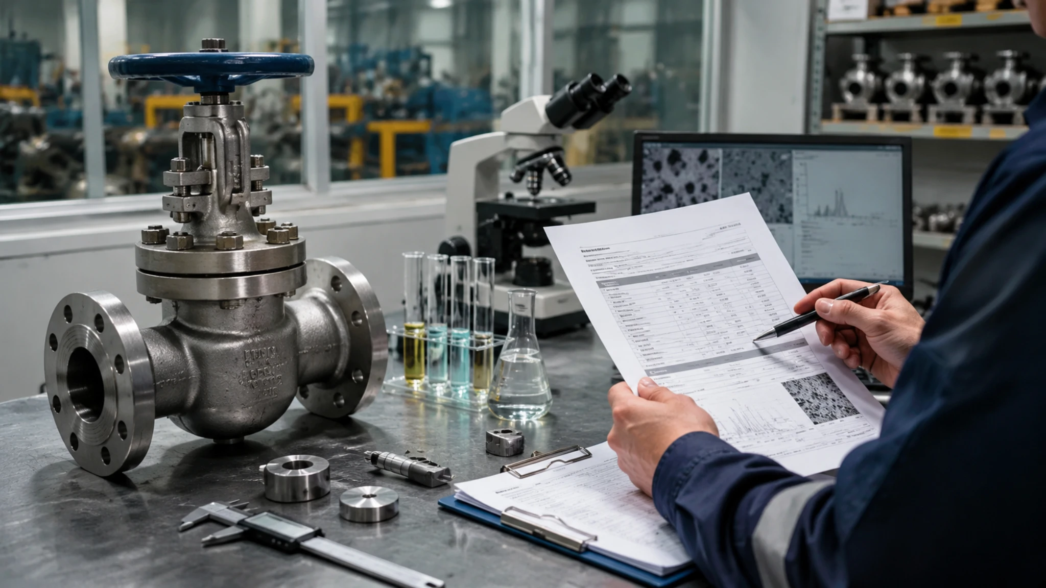
Material Match
Stainless Steel Grades
Cryogenic valve body materials are not just “any stainless steel”. Three parameters must be satisfied at the same time: carbon content, austenite content, and low-temperature impact energy. 304 and 304L are “ambient stainless steel”; below -101°C, martensite phase transformation kicks in and the material embrittles, so 304/304L is banned below that line. 316L is the workhorse of the LNG grade, with carbon content ≤ 0.03% and full 100% austenitic structure retained at -196°C, giving impact energy ≥ 60J. Forging and casting are two separate product lines: forging delivers higher strength at higher cost, while casting suits complex body geometries at lower cost.
| Temperature Class | Cast Steel (≤ 36″) | Forged Steel (≤ 48″) | ASTM Standard | Typical Impact Energy |
|---|---|---|---|---|
| -46°C | LCC / LCB | LF2 | ASTM A352 / A350 | ≥ 18J |
| -101°C | LC3 / CF3 / CF8 | LF3 | ASTM A352 / A350 | ≥ 20J |
| -196°C (LNG grade) | CF3M / CF8M | F316 / F316L | ASTM A351 / A182 | ≥ 60J |
- Carbon content difference: CF3M cast carbon ≤ 0.03%, F316L forged carbon ≤ 0.03%, nominally the same
- Smelting process: F316L goes through electroslag remelting (ESR) and actual carbon content can be pushed below 0.018%
- High-pressure recommendation: For pressure above 50 barg, always specify F316L forging and exclude CF3M casting
For LNG applications, the choice between cast and forged is not just about cost. Forged F316L delivers finer grain structure, better low-temperature impact consistency, and tighter dimensional tolerance, which is critical for high-pressure service above 50 barg. Cast CF3M is more economical for low-pressure (below 15 barg) tank farm service where the cost saving outweighs the performance trade-off. Some EPC procurement specs mistakenly treat CF3M and F316L as interchangeable above 50 barg, and that is the most common cause of field failure I have seen in the past decade.
One rule of thumb I share with junior engineers: for any LNG service above 15 barg, just default to forged F316L. The unit price premium over cast CF3M is typically 20 to 30%, but the lifecycle saving from avoided seat replacements, packing adjustments, and unplanned shutdowns easily pays back the premium within 2 to 3 years. The only case where cast CF3M still wins is on very large valves (above 24 inches) where forging capacity is limited and the lead time from the forge shop becomes the dominant schedule risk. In that single edge case, the lower-pressure rating of CF3M is the trade-off, not the cost.
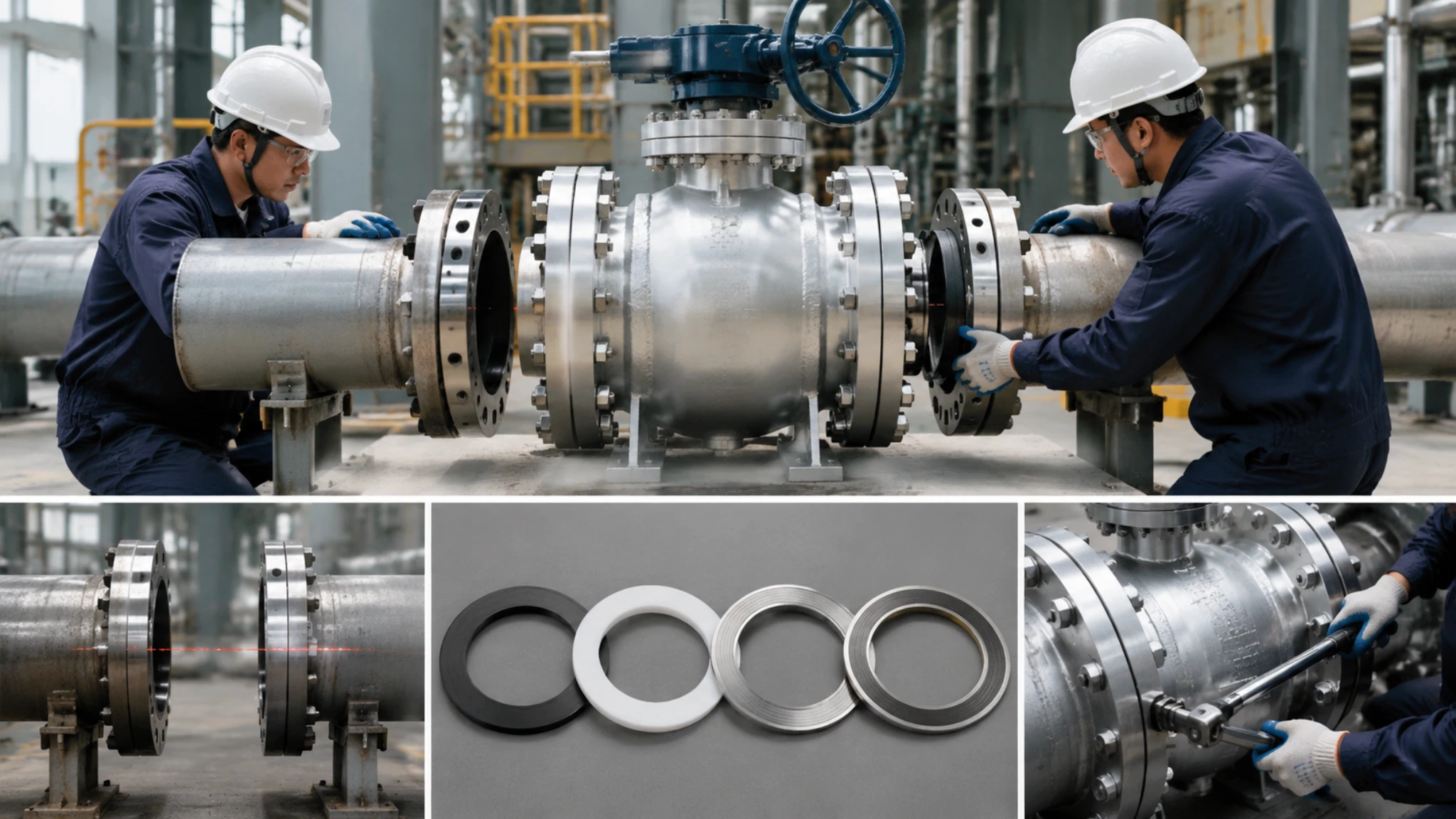
Low Temp Seals
“The seat is the heart of the valve, the seal is the soul. The seat and the packing of a cryogenic valve decide roughly 80% of the failure modes the valve will ever see.” — That was the opening line from the technical director the first time I attended training at a German valve maker in 2017.
The biggest difference between cryogenic valve sealing components and ambient-temperature valve seals is that the material selection is driven not by chemical compatibility but by the glass transition temperature (Tg). For example, a PTFE seat is soft at room temperature (Shore D 55), but once the temperature drops below -100°C, the PTFE enters a glassy state, loses nearly all of its elasticity, and at -196°C micro-cracks appear, causing seal failure. Cryogenic soft seats must use PCTFE (polychlorotrifluoroethylene, Tg = -50°C) or reinforced PTFE (loaded with glass microbeads or carbon fibre to push Tg down to -80°C). Hard seats go to metal-to-metal, typically with Stellite alloy overlay welding.
The stem packing box is another failure point that is easy to overlook. Under a -196°C media environment, conventional asbestos or flexible graphite packing shrinks 2 to 4%, which drops the sealing pressure. Cryogenic packing box design has three requirements: total packing length ≥ 50 mm (BS 6364 requirement), packing material must contain flexible graphite or pure PTFE (asbestos fibre is banned), and a steam or electric tracing jacket is installed on the outside of the packing box to keep the packing working temperature above 0°C. CARILO field data: traced packing 5-year replacement rate 8%, untraced packing 3-year replacement rate 45%, and the traced option is the cheaper one in the long run.
One detail I want to flag: the PTFE family shows wildly different behavior depending on the additive. Virgin PTFE starts losing elasticity around -50°C and becomes fully glassy at -80°C. Glass-filled PTFE pushes the glass transition down to -80°C but introduces abrasive wear on the seat. Carbon-filled PTFE goes to -60°C but conducts static electricity. For LNG-grade soft seats, my rule of thumb is to specify PCTFE for temperatures down to -150°C, and reinforced PCTFE for the -150°C to -196°C band where pure PCTFE starts to creep.
Extended Bonnet Design
The extended bonnet is the most critical “at-a-glance” design feature of a cryogenic valve. Between the body and the bonnet, there is a 200 to 500 mm long cylindrical neck that fully separates the packing box from the cryogenic media, allowing the packing to operate in the ambient zone outside -196°C. Neck length selection follows three rules: neck length equals cold insulation layer thickness plus 200 mm safety margin plus 100 mm maintenance access, all three segments added together give the minimum. The first time I saw a 380 mm neck design with 18°C packing temperature was at an 80,000 m³ LNG storage project in Guangdong in 2018, and I remember thinking: this is what professional engineering looks like.
- Neck length calculation: Cold insulation (PU foam plus aluminium foil) is usually 80 to 150 mm thick, and the neck must be ≥ 280 mm to keep the packing box completely outside the cold insulation layer
- Neck wall thickness calculation: The neck wall pressure-bearing area is calculated by the ASME B16.34 thin-wall cylinder formula. For Class 300 service, a 12″ valve neck wall must be ≥ 8 mm; for Class 600, ≥ 10 mm
- Cold bridge prevention: A PUF cold insulation collar (≥ 30 mm thick) is fitted at the neck-to-body joint to stop cold from being conducted along the metal neck wall into the packing box, which would form a “cold bridge”
- Neck material selection: Usually the same material as the body (F316L or CF3M). Dissimilar-material welding between neck and body is not allowed, because the mismatch in low-temperature thermal expansion coefficients tends to crack the weld
In my earlier projects I saw suppliers offering 150 mm neck length on 12″ Class 600 cryogenic ball valves, claiming it was enough. In reality 150 mm barely clears the cold insulation layer and the packing box still gets cold-soaked. The valve passed factory tests but failed within 6 months in service due to packing hardening. The lesson: never accept a neck shorter than 280 mm on any cryogenic valve regardless of what the supplier says, and verify the cold insulation thickness before signing off on the procurement spec.
Run these 9 sections against your own duty loop and you can cut off 90% of the selection pitfalls. CARILO Cryogenic valves carry dual BS 6364 + ISO 28921-2 certification. Quotations: info@carilovalve.com.

")