
Threaded ball valves are suitable for pipelines up to DN50. Installation is straightforward: wrap the threads with PTFE tape and tighten. Their pressure rating is about 68 bar.
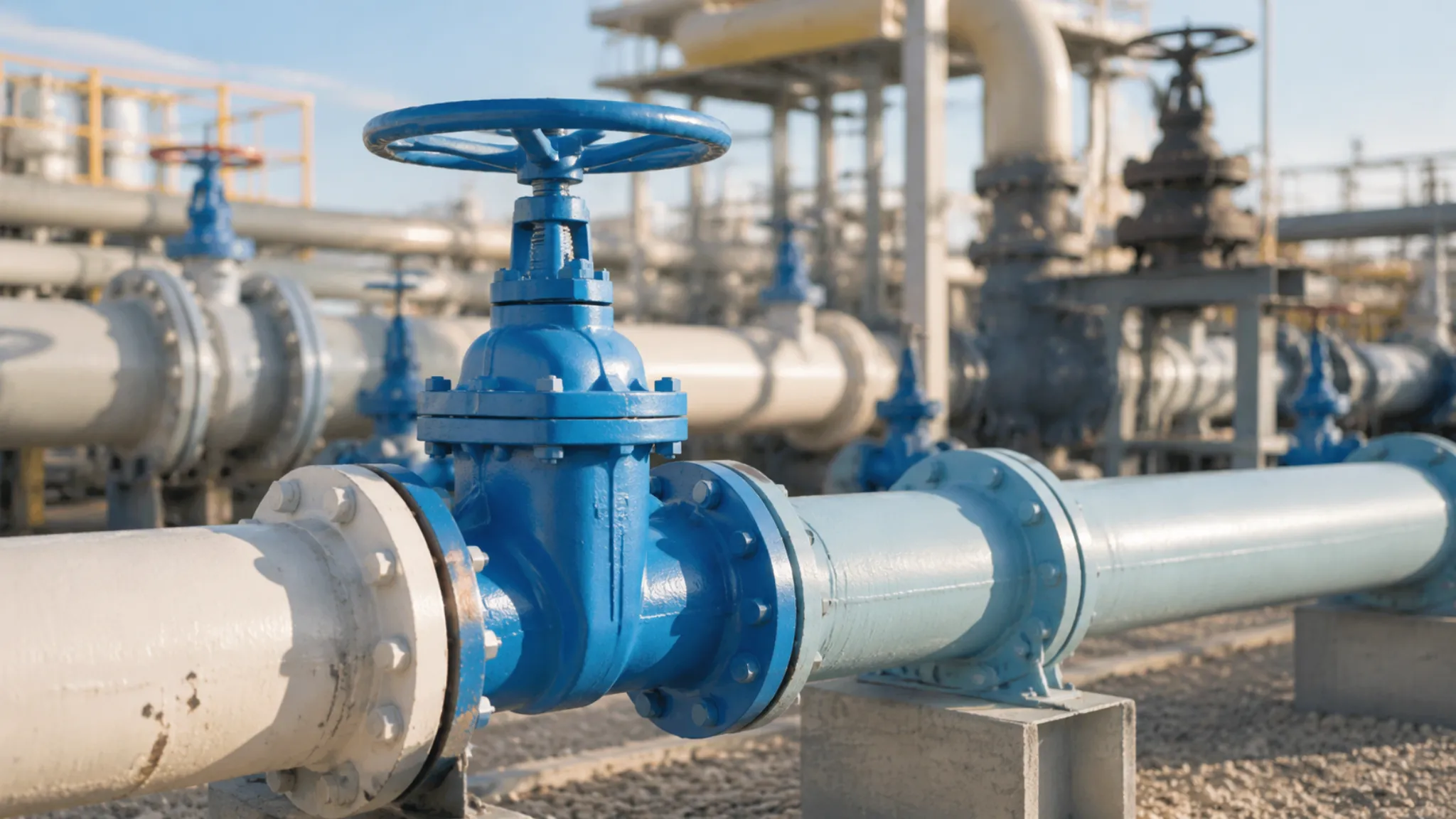
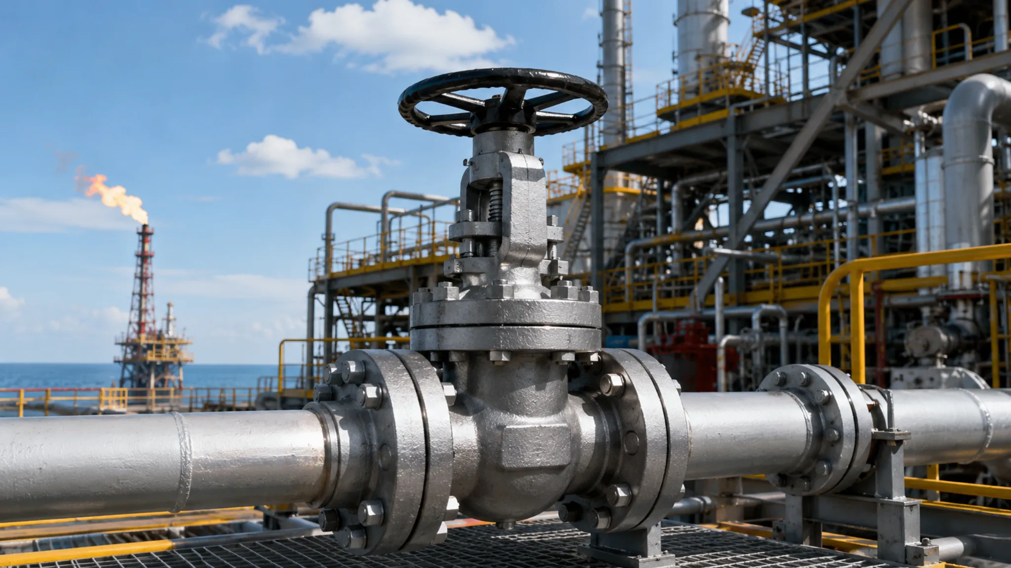
Flanged ball valves are designed for high-pressure systems above DN50. They require a gasket and diagonal cross-tightening of the bolts. With pressure resistance up to 420 bar, they offer better sealing performance and easier removal.
installation method
NPT threaded ball valves manufactured to ASME B1.20.1 are suitable for pipe sizes up to DN50 (2 inches).
Installation relies on PTFE thread seal tape, with pipe wrench torque typically kept between 50 and 100 N·m, and a standard installation time of 3 to 5 minutes.
Flanged ball valves manufactured to ASME B16.5 are intended for pipelines above DN50 and require matching flange gaskets and high-strength bolts for assembly.
A single 8-inch Class 150 flanged valve requires diagonal tightening of eight 5/8-inch bolts. The torque wrench is typically set to 120 N·m, and installation takes about 25 minutes.
The flange design supports non-destructive radial removal. Replacing a threaded valve, by contrast, often requires physically cutting both ends of the rigid pipeline.
Space Envelope Requirements
A 1-inch NPT threaded ball valve is compact, with dimensions close to the pipe wall profile. Its overall length is only 85 mm, and its widest point is just 60 mm. That size allows it to fit inside compact skid-mounted equipment where pipe spacing is only 100 mm. Replace it with a Class 150 flanged ball valve of the same size and the two large flanges immediately increase the envelope. The overall length grows to 127 mm, and the outer diameter expands to 108 mm.
At a chemical plant in Texas, pipe routing crews had to use 3D modeling to check for interference. With threaded valves, the center distance between two straight pipes could be reduced to 100 mm. In a flanged system, that no longer works. The edges of adjacent flanges can easily clash, so the minimum center distance for the same pipe size must be kept above 160 mm.
Many designers forget to account for the operating handle. A standard straight handle requires a full 90-degree swing. The steel handle on a 2-inch flanged ball valve is as long as 150 mm. You need a half-circle clearance zone with a 150 mm radius directly above the valve body, or the handle will hit nearby equipment during operation.
If space is tight, a butterfly-style T-handle is the better option. Because the shorter handle is split evenly to both sides, the swept area is reduced by 50% immediately. After fitting a 1-inch NPT threaded valve with a T-handle, the total operating width drops to just 55 mm.
Flanged valves are bulkier, and you also need to leave enough room for the tools used during installation and maintenance:
- The nose of a pneumatic drilling tool requires at least an 85 mm operating radius
- The reaction foot of a hydraulic torque wrench needs a 45 mm support zone
- A bolt tensioner requires 150 mm of vertical headroom above it
- When using a manual wrench, the swing angle must never be less than 30 degrees
With cryogenic pipelines, the insulation makes the valve envelope even larger. At the LNG terminal in Houston, the -196°C pipeline was fully sprayed with polyurethane foam. The flanged ball valve was enclosed in a rigid insulation box 100 mm thick. Because of the projecting flanges, the total volume of that insulation box was fully three times larger than that of an equivalent threaded valve.
If you mount a pneumatic actuator on top of the valve, the required space increases dramatically. A rack-and-pinion pneumatic cylinder sits on the valve stem. On a 4-inch Class 300 flanged ball valve fitted with a double-acting actuator, the total height jumps by 320 mm. The stainless steel fittings for the side air line also protrude another 40 mm outward.
Threaded ball valves do not require heavy tools at all. Workers can handle the entire installation using only two standard 18-inch pipe wrenches. One grips each side of the valve body at the hexagonal flats. During the job, the worker’s full operating range stays within a cylindrical working space about 400 mm in diameter.
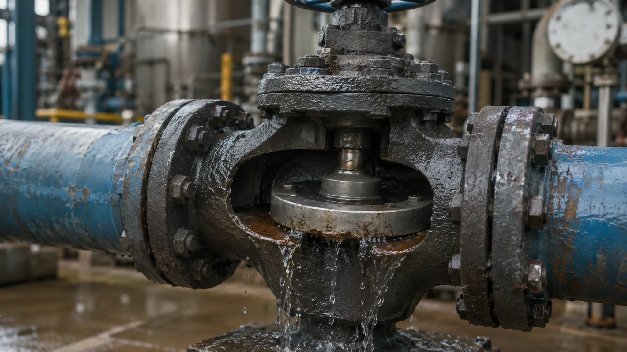
Flanged assembly demands very strict pipe alignment. ASME B31.3 limits the flange face parallelism deviation to no more than 1.5 mm per meter. Replacing a spiral wound gasket also requires mechanically spreading the two ends apart, which means extra clearance must be reserved:
- A spiral wound gasket with inner and outer rings is 4.5 mm thick
- A mechanical spreader needs 6 to 8 mm of separation to generate force
- To pull a bolt out completely, the gap must exceed the bolt length by 13 mm
- An additional 300 mm of space below is needed to hang a safety net for dropped nuts
Most flanges in high-pressure systems use RTJ ring joints. The octagonal soft-iron ring gasket is tightly seated inside a trapezoidal groove. To remove a 10-inch Class 1500 flanged ball valve, the connected carbon steel pipes must be forced outward by 12 mm. This pushing force is extremely high, so the support blocks beneath the pipe rack must be lubricated to reduce friction.
On North Sea offshore drilling platforms, the piping network is packed almost like a spiderweb. After running the layout through Navisworks, engineers imposed a hard rule: all Class 600 flanged valves had to be staggered. The centerlines of adjacent valves had to be at least 150 mm apart, or workers simply could not get their hands in to remove the bolts.
As the valve gets larger, the support structure underneath must also become stronger. MSS SP-58 clearly requires a load-bearing support base to be welded within 500 mm of each end of a heavy flanged ball valve. The support structure itself also takes up space:
- The steel canister around a spring hanger has a diameter of 120 mm
- The welded steel plate under a saddle support can be as wide as 200 mm
- Once a U-bolt clamp is tightened, the threaded ends protrude another 20 mm
- The PTFE slide plate underneath measures 150 mm square
A 2-inch NPT threaded ball valve weighs less than 2.5 kg. A flanged valve of the same size can weigh 12 kg. Designers do not need to provide dedicated supports for threaded valves. These lightweight parts can simply hang in line with the pipe and be carried by standard pipe supports spaced every 3 meters.
Large chemical plant pipe racks are often stacked in multiple tiers. If a flange connection above drips even a small amount of liquid, no sensitive equipment can be placed below it. For that reason, the 300 mm zone directly below a flanged ball valve must never contain expensive instruments or cable trays. Threaded valves, with their tighter joints, are often allowed to pass just 150 mm above electrical cabinets.
Tools & Labor Time
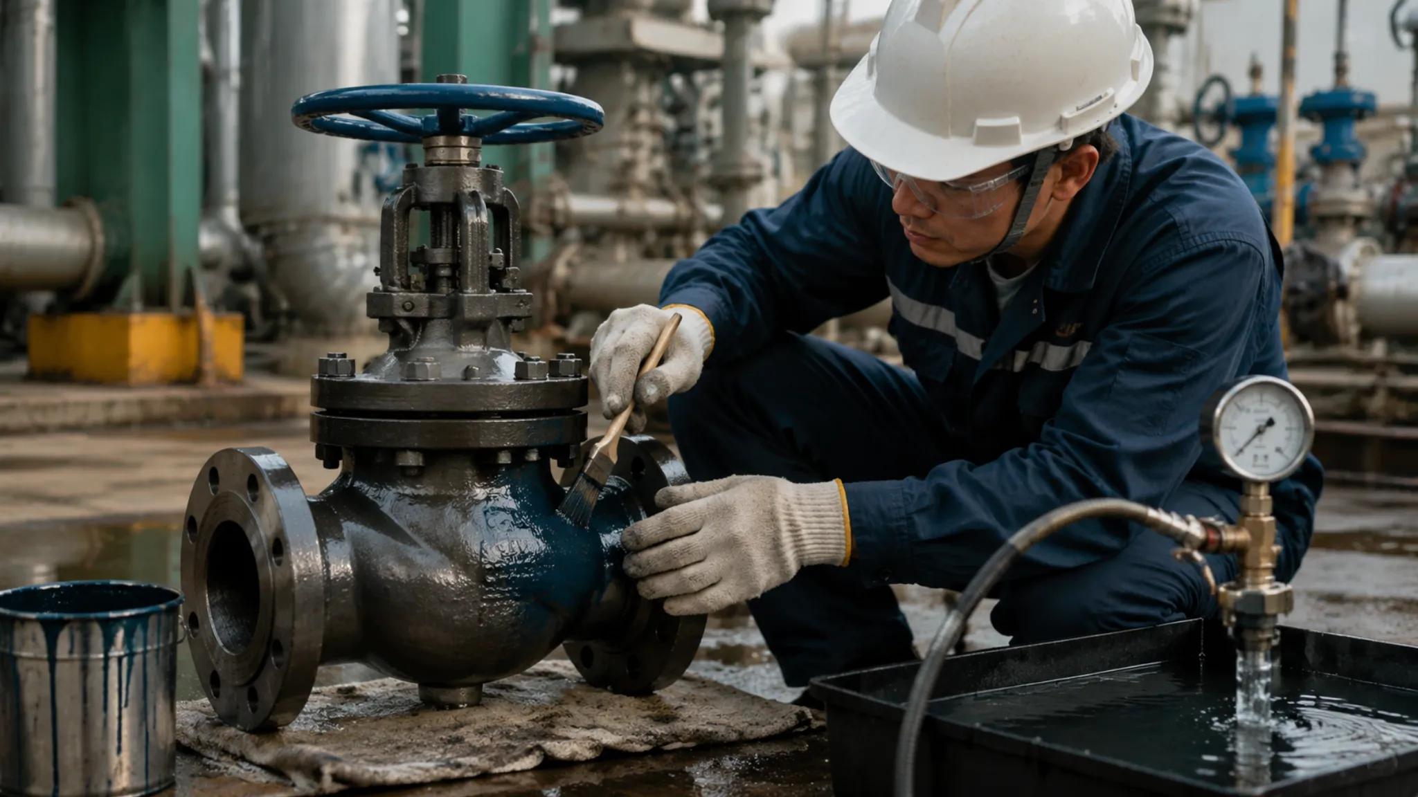
Installing an NPT threaded ball valve up to 2 inches requires very little equipment. Pipefitters typically carry two 18-inch Ridgid heavy-duty pipe wrenches and a roll of high-density PTFE thread seal tape compliant with MIL-T-27730A. The installer wraps the male thread clockwise three to five turns and applies a layer of Loctite 565 thread sealant.
One worker can install and tighten a 1-inch threaded valve on a pipeline in under 5 minutes. The pipe wrench torque at the hex flats is usually around 65 N·m. For a 2-inch pipe, the larger thread engagement requires a 24-inch pipe wrench and much greater force, with total installation time reaching about 12 minutes.
Flanged ball valves are a completely different story and require heavy-duty assembly tools. Under ASME B16.5, the flange face must not be scratched. Pipe wrenches are too crude and cannot be used on the sealing surface. The standard tool set becomes a ratchet wrench, flange alignment pins, and a digital torque wrench.
| Valve Type & Size | Fasteners & Sealing Consumables | Required Assembly Tools | Standard Crew Size | Average Time per Valve |
|---|---|---|---|---|
| 1″ NPT female thread | PTFE tape + thread sealant | 14/18-inch pipe wrench | 1 person | 5–8 minutes |
| 2″ NPT female thread | High-density PTFE tape | 24-inch heavy-duty pipe wrench | 1–2 people | 10–15 minutes |
| 4″ 150# flange | 16 × 5/8″ bolts + spiral wound gasket | Torque wrench + vernier caliper | 2 people | 40–55 minutes |
| 10″ 300# flange | 32 × 1″ bolts + metal gasket | Hytorc hydraulic wrench + crane | 3–4 people | 110–150 minutes |
The number of bolts increases rapidly with valve size and pressure class. A 4-inch Class 150 flanged ball valve requires a total of 16 ASTM A193 B7 5/8-inch stud bolts across both ends. Tightening cannot be done arbitrarily. Workers follow ASME PCC-1 and tighten the bolts in a diagonal star pattern.
Cross-tightening is labor-intensive. The first pass is done at 30% of rated torque, about 40 N·m. The second pass increases to 60%, and the third pass reaches the full 120 N·m. After that, a vernier caliper is used to measure the exposed thread lengths of adjacent bolts. If the difference exceeds 1.5 mm, the bolts must be loosened and retightened. Even two experienced Gulf Coast pipefitters in the U.S. will spend at least 45 minutes installing a single valve.
Once the size exceeds 6 inches, manual tightening becomes pure physical labor, especially on Class 600 and above. An 8-inch Class 600 flanged ball valve uses studs up to 1-1/8 inches in diameter, and the crew must bring in a Hytorc hydraulic torque wrench.
With a 700 bar hydraulic pump station connected, each nut takes about 15 seconds to tighten. Tightening all 32 fasteners to spec takes 25 minutes of hydraulic wrench runtime alone. Before that, the 200 kg-plus valve body must be leveled and aligned with a chain hoist, which can easily take another half hour.
The maintenance and removal cost gap is even greater. A refinery in Louisiana calculated the labor cost of a single maintenance job. A pipefitter’s hourly wage plus benefits came to USD 85. If a flanged valve failed, two fitters with the right tools could spread the flanges by 8 mm, remove the old valve, install a new gasket, and finish the full replacement in two hours, for a labor cost of USD 340.
If a threaded ball valve is locked into the middle of a straight pipe run, replacement becomes a different story. Workers must use thermal cutting to cut both ends and remove the valve together with a section of pipe. They then carry a portable Ridgid 300 threading machine onto the scaffold and cut new threads onto both freshly cut pipe ends.
Reworking takes a long time. The carbon steel cutting head must turn through cutting oil multiple times before it can form the standard 1:16 taper thread. Two unions must then be added to the pipeline as a repair patch.
Between destructive removal and reinstallation, the total labor is at least three full man-hours, not including the fire tent required for hot work. Once the fire watch and fire hose setup are included, the on-site labor cost of replacing one valve can easily exceed USD 1,200.
The bottom of the labor sheet is filled with time-consuming preparation work:
- Deburring an NPT pipe end after threading with a reamer: 2 minutes
- Running and connecting heavy-duty hoses for a pneumatic impact wrench: 15 minutes
- Brushing rust-preventive grease off an octagonal metal ring gasket before installation: 10 minutes
- Rigging a large valve with four-point polyester anti-sway lifting straps: 20 minutes
- Applying nickel anti-seize compound to each B7 bolt thread: 8 minutes
Desalination contractors like pneumatic tools because they are fast. An Ingersoll Rand 1-inch square-drive impact wrench can deliver a peak torque of 2,700 N·m in a second. On a 10-inch weld-neck butterfly flange, it can drive a 1-1/4-inch nut home in just 3 seconds.
That kind of high-power impact wrench is strictly prohibited on large flanged ball valves. The shock load can cause uncontrolled compression of the graphite spiral wound gasket and permanently crush it. Crews must stick to the slower, staged hydraulic tightening process, with no realistic way to save time.
In confined underground valve pits, the labor time for flange assembly rises sharply. On an underground gas pipeline repair in Texas, two workers barely had enough room to turn around once they were inside the pit. A long-handled torque wrench was impossible to use, so they had to work nut by nut with a short open-end wrench. A 6-inch flange that would normally take 40 minutes ended up taking two and a half hours.
Small threaded valves, by contrast, are much easier to handle in narrow corners. Even with only 40 mm of clearance between the pipe and the wall, a worker can still insert half the pipe wrench head and get a solid bite on the valve body. By turning the wrist just 10 degrees at a time, the worker can slowly drive the full NPT thread into the female pipe within 5 minutes.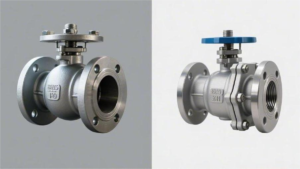
sealing performance
Flanged ball valves use face sealing with PTFE or spiral wound metal gaskets. Leak prevention relies on bolt preload, in line with ASME B16.5.
Their pressure range covers Class 150 to Class 2500 (20 to 420 bar), with fugitive leakage rates below 100 ppm, making them suitable for harsh service in DN50-and-above large-diameter piping.
Threaded ball valves depend on NPT or BSPT thread engagement together with PTFE tape to form a mechanical seal, with a pressure limit of 1000 to 2000 WOG (68 to 138 bar).
Because they are generally limited to pipe sizes below DN50, the mechanically engaged threads are more likely to develop micro-gaps and leakage under strong vibration or thermal shock.
Sealing Differences
Take NPT threads as an example. Their taper is fixed at 1 degree 47 minutes. When the worker threads the pipe into the valve, the metal threads bite into each other, but microscopic gaps of several microns still remain. A plumber then uses 0.075 mm thick PTFE tape to fill those spiral leakage paths. Once the internal pressure reaches 68 bar, the fluid continuously searches for weak points in the tape and pushes outward.
Under API 598, a valve passes if no visible water droplet appears during a 15-second hold at 6 bar and room temperature. But in industrial service, fluid temperature can quickly rise to 150°C, and thermal expansion varies from one material to another. PTFE softens when heated and does not return to its original thickness after cooling, so leakage paths can appear immediately.
- ANSI B1.20.1 limits the effective thread engagement length (L1) of a 2-inch pipe to 17.3 mm
- PTFE tape thickness cannot realistically exceed 0.2 mm, or the thread will not seat fully
- Liquid PTFE-based thread sealants such as Loctite 577 require a full 24 hours to cure
- Once hydrostatic pressure exceeds 138 bar (2000 WOG), the filler material can be torn apart instantly
Flanged ball valves prevent leakage by face sealing. Once high-strength bolts are tightened, they generate tens of thousands of newtons of tensile force, pulling the two flat flange faces tightly together. The gasket is compressed by 20% to 30%. The spiral serrations machined into the flange face, with roughness between Ra 3.2 and 6.3 μm, are completely filled by the gasket material.
Four or eight ASTM A193 B7 high-strength bolts surround the flange. Using a torque wrench, workers tighten them in a diagonal sequence to 150 N·m, distributing the gasket load evenly. Even a Class 150 flange can easily hold 20 bar of static water pressure under that compressive force.
- With a Class 600 flange, thicker bolts raise the pressure rating to 100 bar
- With a spiral wound gasket made of 304 stainless steel strip and flexible graphite, the seal remains tight even at 500°C
- On toxic VOC service, the fugitive emission rate at the flange interface can be kept below 100 ppm
- When tested with a helium mass spectrometer, the allowable leakage level can be as low as 1×10^-6 mbar·l/s
At the outlet of a plant centrifugal pump, pipelines often vibrate continuously at 50 to 120 Hz throughout the year. This constant high-frequency motion causes several microns of lateral displacement between NPT thread flanks. Over a few months, the PTFE tape is worn away completely, and liquid begins to seep along the thread root clearance.
By contrast, the gasket trapped between two flanges has a small degree of resilience. When 50 to 120 Hz vibration passes through, the gasket absorbs and dissipates part of the movement on its own. API 622 low-emission testing requires the valve to undergo five full thermal cycles between room temperature and 200°C. The flange bolts still retain essentially the same preload they had when first tightened.
- Class 2500 extreme-pressure flange gaskets can withstand destructive hydrostatic testing at 420 bar without failure
- After 100,000 vibration cycles on a test rig, torque loss on high-strength nuts remains below 5%
- In a -46°C liquid propane network, specially designed low-temperature gaskets remain elastic instead of freezing stiff
- Underwater testing at 6 bar compressed air for 3 minutes must show zero bubbles
DN150 gathering lines in North American shale oil fields are supported above ground on pipe racks. Ball valves weighing several hundred kilograms are carried entirely by the steel pipes connected at both ends. Tens of thousands of newtons of shear and bending force are concentrated at the joint. With their much larger contact area, flange faces can absorb these radial and axial loads with little difficulty.
The North American ASME B31.3 process piping code sets strict inspection requirements. Workers use ultrasonic thickness gauges to verify that at least 3 mm of corrosion allowance remains in the metal wall behind the flange. If a flange develops slight leakage while pressurized, live leak-sealing crews can inject polymerizing sealant into the outer flange gap. A threaded leak cannot be repaired that way. The entire line must be shut down, drained, and cut apart so the pipe can be rethreaded.
ASME also requires 100% radiographic inspection of flange welds on pipelines carrying highly toxic fluids. Workers can remove all bolts from a DN200 flange in 5 minutes using a pneumatic torque multiplier. Removing threaded piping requires rotating the entire steel pipe with a large pipe wrench, which means at least 500 mm of surrounding operating space must be available. During a plant overhaul, replacing a brand-new PTFE flange gasket costs only a few dollars and restores sealing performance to near-original condition.
Leak Testing
ASME B16.34 sets a high testing threshold for industrial valves. In the factory, inspectors clamp a Class 150 flanged ball valve onto a hydraulic test bench. Water at room temperature is pumped into the valve body until the pressure gauge reaches 30 bar. That is 1.5 times the normal operating pressure of 20 bar for the flange at ambient temperature.
A 4-inch flanged ball valve must hold that pressure for a full 60 seconds. The inspector shines a flashlight around the carbon steel flanges on both ends. The A216 WCB cast steel body must not release a single droplet of water. The surrounding graphite spiral wound gasket keeps the 30 bar pressure sealed inside the line.
Threaded ball valves follow a different test sequence. Take a 2-inch NPT female-thread brass ball valve as an example. Its hydrostatic test limit is only 104 bar. The tensile strength of brass places a hard cap on the test value. During the 60-second hold, even small machining tolerances at the thread root can allow visible seepage under that pressure.
Once the shell test is finished, the procedure moves to the seat tightness air test under ISO 5208. Compressed air at 6 bar is introduced into the half-open ball valve. The water surface in the test tank must remain perfectly calm. The PTFE soft seat must achieve the highest Rate A classification, which means absolutely no bubbles are permitted during the required 15-second hold.
| Connection Design | Applicable Test Standard | Maximum Shell Hydro Test Pressure | Seat Air Test Requirement | Allowable Helium Micro-Leakage |
|---|---|---|---|---|
| ASME flange | API 598 / API 6D | 420 bar (Class 2500) | 6 bar, 120-second hold, no bubbles | Within 100 ppm |
| NPT thread | MSS SP-110 | 138 bar (2000 WOG) | 5.5 bar, 15-second hold, no bubbles | No mandatory limit |
North American EPA rules for hazardous gas lines in chemical plants are strict. API 624 fugitive emission testing is specifically intended to catch leakage. Technicians fill a 6-inch flanged ball valve with methane gas. A pneumatic actuator repeatedly opens and closes the ball, completing 310 full operating cycles.
Those 310 friction cycles are combined with heating the valve from room temperature to 260°C. The repeated thermal expansion and contraction stress both the packing and the gasket. Inspectors then scan the flange joint from a distance of 1 cm using an EPA Method 21 probe at a speed of 10 cm per second. The methane concentration shown on the screen must not exceed 100 ppm.
Most threaded ball valves are not even suitable candidates for this test. PTFE thread tape softens and melts long before 260°C. Once the NPT thread loses that 0.1 mm plastic filler layer, high-pressure methane rushes out through the 1 degree 47 minute tapered thread gap.
- For cryogenic testing, technicians immerse an extended-bonnet flanged ball valve in liquid nitrogen at -196°C
- Because carbon steel becomes brittle at this temperature, the valve body is upgraded to 316L stainless steel
- The line is internally pressurized with 15 bar of high-purity helium
- A collection hood is used to accurately measure the volume of helium escaping from the valve
BS 6364 defines the acceptance line for cryogenic service. A 3-inch flanged ball valve must not leak more than 300 cubic millimeters of helium per second. The matching Kel-F lip seal on the flange becomes extremely hard at -200°C LNG service temperature, and sealing is maintained almost entirely by the 200 N·m preload applied by the high-strength bolts.
Threaded fittings are essentially absent from LNG receiving terminals. At -196°C, the extreme low temperature causes irreversible microscopic contraction in the threads. No matter how tightly two NPT steel pipes are screwed together at room temperature, once they are chilled with liquid nitrogen, the gap between the threads opens instantly. Helium at 15 bar can leak out by several thousand cubic millimeters per second.
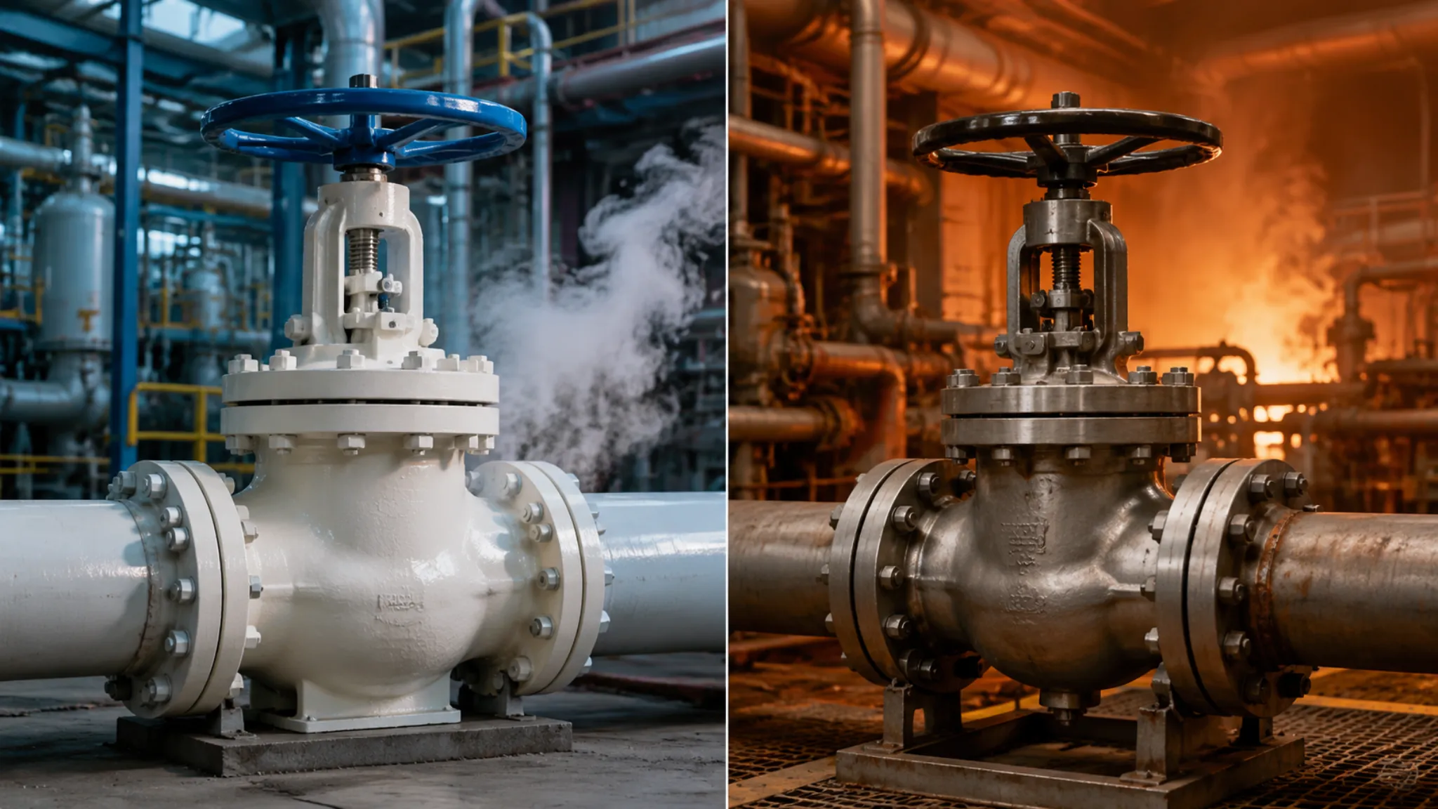
In a refinery fire, shutoff valves serve as the last line of defense. API 607 fire testing is extremely severe. Several industrial burners blast a DN150 flanged ball valve for a full 30 minutes. The metal surface glows red under flames between 750°C and 1000°C. The internal PTFE seat burns away in less than 10 minutes.
Once the stainless steel ball loses its polymer support, line pressure pushes it forward until it slams against the machined metal stop ring inside the valve body. The emergency metal-to-metal backup seal then takes over. Throughout the full 30-minute fire period, leakage must remain below 25 mL per minute for each inch of nominal pipe size.
After the flames are extinguished, cooling water is sprayed over the red-hot valve. Flange bolts made from ASTM A193 B8M keep the carbon steel flange faces locked together and survive the severe thermal shock. The cooled valve body is then repressurized to 2 bar water, and the external shell must remain completely drip-free.
If you place a standard brass threaded ball valve on an API 607 fire test rig, the brass softens and deforms in less than 5 minutes. Line pressure then escapes through the loosened thread joint. The North American ASME B31.3 petrochemical piping code explicitly prohibits tapered threaded connections in piping that carries flammable, explosive, or high-temperature media.
External Environment
At Gulf Coast refineries in Texas, centrifugal pumps built to API 610 operate continuously. The piping and valves are forced into high-frequency vibration between 60 and 120 Hz. A 3-inch NPT threaded ball valve hanging on a pump discharge line must absorb all mechanical stress through only a few engaged thread turns.
Once the vibration amplitude reaches 0.5 mm, the stress concentration factor at the thread root can rise above 3.0. The 0.075 mm thick PTFE tape wrapped by the installer can be destroyed in less than a month. Fluid then escapes through the 1 degree 47 minute tapered thread gap.
ASME B31.3 restricts the use of threaded joints on reciprocating compressor piping. Vibration loads can easily crack the already weakened thread roots.
If the same vibration frequency is transmitted to a Class 300 flanged ball valve, the outcome is very different. Eight 5/8-inch high-strength bolts clamp the flange faces tightly together. The 3.2 mm metal spiral wound gasket in between acts as a natural damper, absorbing high-frequency displacement within the flexible graphite filler.
In Alberta’s oil sands region, winter night temperatures can fall to -40°C. Under direct sunlight, exposed carbon steel piping can climb to +45°C during the day. A 20-foot straight pipe section can expand and contract by nearly 10 mm across an 85°C temperature swing.
That thermal movement pulls directly on the valve joints. On threaded pipe fittings up to 2 inches, the engaged threads are subjected to high axial tensile force. The sealant at the thread interface becomes brittle in deep cold and can crack immediately once pulled.
- Flanged ball valves absorb several millimeters of movement through the gasket’s elastic recovery, typically 15% to 30%
- ASTM A320 L7 low-temperature bolts retain high yield strength at -46°C without brittle fracture
- A Class 600 flange, 24 mm thick, provides enough structural stiffness to resist deformation
Offshore drilling platforms in the Gulf of Mexico are constantly exposed to salt spray. ISO 12944 classifies this environment as the severe C5-M corrosion category. Chloride-laden sea air reaches every exposed metal surface.
When a worker tightens an NPT threaded joint, the teeth of the pipe wrench damage the galvanized coating or paint on the steel pipe. The exposed thread flanks then become ideal initiation points for electrochemical corrosion. Under ASTM B117 5% salt spray testing, exposed carbon steel threads can seize solid in under 200 hours.
When maintenance crews on offshore platforms encounter a threaded valve seized by corrosion, they usually cannot remove it with a wrench. Their only option is to cold-cut the entire pipe section out.
Switching to a 316L stainless steel flanged ball valve significantly improves corrosion resistance at the external surface. The flange faces are compressed tightly enough that external saltwater cannot penetrate the sealing groove. A 250 μm zinc-rich epoxy primer applied around the outer flange can withstand 1,000 hours of salt spray exposure.
Water transmission lines crossing the Nevada desert may experience minor ground settlement. Schedule 80 heavy-wall pipe sections filled with water can sag under their own weight across spans of dozens of meters, and the bending load is concentrated at the valve joint. An 8-inch flanged ball valve alone can weigh 150 kg.
The two flanges are connected by twelve 3/4-inch bolts. This bolted joint can carry the large bending moment caused by pipeline settlement. In structural simulation, engineers applied an eccentric torque of 500 N·m, and the flange sealing surface showed only minimal tilt. The gasket still maintained leak-tight performance at 20 bar.
An NPT pipeline cannot tolerate the same settlement. Half the wall thickness is effectively removed during threading. Once external load is applied, the weakened thread roots become prone to fatigue cracking.
application range
Threaded ball valves (NPT/BSPT standard) are suitable for DN15 to DN50 (1/2″–2″) piping, with a pressure ceiling of 1000 WOG. They are commonly used in commercial building piping systems and light HVAC lines.
Flanged ball valves (in accordance with ASME B16.5) cover larger diameters above DN50, with pressure classes from ANSI Class 150 to 2500 (up to about 420 bar). They can also meet API 607 fire-safe requirements, making them suitable for high-temperature, high-pressure service in refineries and deepwater drilling platforms.
The practical dividing line between the two is defined by pipe size, peak system pressure, and the expected frequency of removal and maintenance.
Pressure & Temperature
At a motel in Texas, the domestic water network runs warm water year-round. The brass NPT threaded ball valves there are marked 600 WOG, which means they can handle about 41 bar at room temperature. Shower water rarely exceeds 40°C, and the pipe diameter stays below 2 inches, so threaded connections are fully adequate.
Once the water temperature rises above 95°C, the picture changes completely. The piping expands and contracts every day, and 316 stainless steel experiences 16.0 μm/m·°C of thermal strain. Over time, the locked thread engagement is repeatedly pulled and stretched, gradually opening the thread gap. After two or three years of operation, dripping at the threaded joint becomes very likely.
In the high-temperature cracking unit of a Houston refinery, engineers do not use threaded fittings at all. The line carries 350°C superheated steam at 130 bar. Instead, they install Class 1500 carbon steel flanged ball valves. A ring of high-strength bolts around the flange edge holds everything together and distributes the massive internal force.
As temperature rises, the soft seat is the first part to soften, so seat material must be selected according to service temperature:
- PTFE: rated to 150°C, typically used in 1000 WOG threaded valves
- RPTFE: reinforced with glass fiber, suitable up to 204°C
- PEEK: high-hardness engineering plastic, suitable up to 260°C
- Stellite: hard alloy used for full metal sealing above 500°C
API 607 fire testing is highly demanding. The valve must withstand 30 minutes in a fire between 760°C and 980°C. Once the polymer seat has burned away, the backup metal lip inside the flanged ball valve is pushed against the ball by a spring and seals the leak path by force. The thinner wall of a threaded valve is far more likely to soften and collapse in fire conditions.
On deepwater drilling platforms, the high-pressure water injection system can reach 420 bar. The flanged ball valve is forged in one piece from duplex stainless steel. The flange face uses an RTJ groove design, where an octagonal soft-iron ring gasket is compressed into the groove. The higher the pressure, the tighter the metal gasket seats, fully isolating the high-pressure saltwater.
The pressure limit of a flange is built mainly through flange thickness and bolt count:
- Class 150: 19.6 bar, suitable for general industrial water service
- Class 300: up to 51.1 bar
- Class 600: a common refinery baseline, around 100 bar
- Class 1500: standard for hydroprocessing equipment, about 250 bar
- Class 2500: extremely thick-wall construction for deepwater platforms around 400 bar
When temperature moves below zero, metal can become as brittle as glass. At an LNG receiving terminal in Qatar, the line carries cryogenic liquid at -196°C. Standard carbon steel loses toughness at -29°C and can fracture easily. The site therefore requires flanged ball valves made from CF8M austenitic stainless steel, which are cryogenically treated in liquid nitrogen before leaving the factory to relieve internal stress.
A threaded design effectively stops working at -50°C. PTFE tape and sealant shrink and harden, instantly turning microscopic thread clearances into leakage paths. Engineers solve this on flanged ball valves by adding a 250 mm extended bonnet, preventing the -196°C cold from conducting upward through the metal and freezing the stem packing at the top.
Pipe Size & Space
At most installation sites, the practical dividing line is DN50 (2 inches). During HVAC retrofits in the basements of older apartment buildings in Chicago, workers are usually dealing with tightly packed 1-inch or 1.5-inch copper pipe. A threaded ball valve is compact enough to screw directly into the pipe without needing the extra lateral space taken up by flanges.
The external envelope of a threaded connection is typically only 30% to 50% larger than the pipe diameter itself. A standard 2-inch NPT threaded ball valve often has a face-to-face length of only 110 to 150 mm. That allows it to fit easily above ceilings or inside narrow wall cavities, where a simple pipe wrench can lock it in place.
Once the pipe size exceeds DN50 and reaches DN80 (3 inches) or DN100 (4 inches), threaded installation becomes extremely difficult. Workers must use great force just to align and start the large threads. To prevent leakage, a large-diameter threaded connection needs very high torque, which is almost impossible to achieve in a tight equipment room.
- DN15 (1/2″): overall length about 65 mm, suitable for small laboratory gas lines
- DN25 (1″): overall length about 90 mm, standard for hot and cold water branches in commercial buildings
- DN50 (2″): overall length about 140 mm, essentially the practical size limit for threaded ball valves
- Installation allowance: leave 50 mm on each side for tool access, with at least 150 mm wrench swing radius
Once the size increases further, flanged ball valves become the standard choice on site. Flanged valves manufactured to ASME B16.10 have clearly defined face-to-face dimensions. For example, a 4-inch Class 150 flanged ball valve has a face-to-face dimension of about 230 mm. Thick flanges, bolts, and gaskets at both ends add even more to the required envelope.
The flange diameter directly increases the space requirement. On a DN100 pipe, the flange outside diameter can reach 230 mm, more than twice the pipe diameter itself. In a chemical plant pump room in Houston, if two parallel 4-inch lines both use flanged valves, the center distance between the lines must be at least 300 mm.
This larger footprint is the price paid for structural relief. Flanged ball valves are tightened by axial bolt compression rather than rotational thread force. On oil unloading lines at the Port of Rotterdam, 12-inch or even 24-inch large-diameter ball valves commonly have 24 bolts on the flange alone.
| Specification Comparison | 2″ Threaded Ball Valve (NPT) | 4″ Flanged Ball Valve (Class 150) | 12″ Flanged Ball Valve (Class 300) |
|---|---|---|---|
| Overall Valve Length | Approx. 135 mm | Approx. 229 mm | Approx. 502 mm |
| Outer Diameter / Flange Diameter | Approx. 80 mm | Approx. 230 mm | Approx. 520 mm |
| Weight per Valve | Approx. 2.5 kg | Approx. 35 kg | Approx. 420 kg |
| Number of Bolts | 0 (directly threaded in) | 8 pcs (5/8″ bolts) | 16 pcs (1-1/8″ bolts) |
Weight is another unavoidable factor in space planning. A DN15 threaded mini valve weighs only about 0.5 kg and requires no additional support. But at DN200 (8 inches), a flanged ball valve can easily weigh more than 150 kg. At that point, ceiling hangers must be reinforced and floor-mounted concrete pedestals may be required.
The placement of this kind of heavy equipment must also allow for future maintenance access. Space usually needs to be left above the valve stem for removal of the gearbox or operator, while the side must be clear enough for workers to swing a 1-meter torque wrench. If a large-diameter valve is forced into a dead corner, replacing the gasket later may require cutting out the entire pipe section.
- 1/2″–2″: threaded valves are preferred for compact hydraulic skids, furniture systems, and lubricating oil lines
- 3″–8″: flanged valves become the starting point, suitable for plant main water, low-pressure steam, and wastewater treatment
- 10″–36″: heavy flanged valves for crude oil pipelines, long-distance gas transmission, and power plant cooling circulation
- Space estimate: leave maintenance clearance around a flanged valve equal to 1.5 times the valve body diameter
In a London data center cooling system, where every square centimeter of plant room space is valuable, designers used threaded connections on all lines 2 inches and smaller. But on the main inlet and outlet of the chiller, they still required flanged ball valves, because the system had to be removable for inspection every five years.
Repeated disassembly and reassembly gradually wears and deforms the metal threads in a threaded connection, until the entire fitting must be cut out and replaced. A flange connection, by contrast, is a long-term solution: once the bolts are loosened, the valve can simply be slid out. This trade-off of “more space in exchange for less downtime” becomes especially valuable on automated production lines where operating costs are high.
When installing very large valves, lifting clearance must also be considered. Flanged valves above 12 inches usually have lifting lugs cast or welded onto the top. On North Sea drilling platforms, even a few extra decimeters of lifting height can require the deck steel supports to be reworked around them.
Industrial Service & Shutdown Maintenance
At a chemical plant in Louisiana undergoing a once-every-five-years turnaround, downtime costs can reach USD 50,000 per hour. When site engineers prepare the bill of materials, the replacement time difference between threaded and flanged ball valves directly affects how quickly the production line can restart. If all DN50-and-below branches use NPT threaded valves, workers must be equipped with pipe wrenches, PTFE tape, and liquid sealant.
Threaded ball valves are classic “destructive-removal” components. Once the valve core sealing surface is scratched by welding slag in the pipeline and internal leakage begins, maintenance crews cannot simply remove and replace the internal parts while the valve remains in the line. To remove a screw-in ball valve, the two connecting steel pipes must first be cut apart, unless three unions were already installed in advance during initial construction.
Field maintenance records show that removing one rusted 1.5-inch stainless steel threaded ball valve takes an average of 45 minutes, not including pipe cutting, rethreading, or waiting for fresh sealant to cure.
- Threaded valve removal tools: 24-inch heavy-duty pipe wrench, manual or powered threading machine, PTFE tape
- Spare parts logic: internal repair is uncommon; failed valves are usually cut out and scrapped as a whole
- Downtime cost: a single-point failure usually stops the local branch for at least 2 hours, with labor making up the largest share
- Best suited to: light-duty fluid circulation systems where production is non-continuous and the line can be shut off at any time
Flanged ball valves follow a completely different design logic, built for “fast turnaround in service.” Flange faces compliant with ASME B16.5 are clamped axially with a set of bolts. At a crude oil pump station in Houston, workers can loosen eight 5/8-inch bolts with an impact wrench, and the two flanges separate immediately.
This structure allows the valve body to be removed parallel to the pipe axis without welding or cutting. For a 4-inch Class 150 flanged ball valve, a skilled crew using lifting slings can complete the removal in less than 15 minutes. Once the old graphite gasket residue is cleaned off the faces, a new valve can be inserted, the bolts retightened, and the line immediately returned to pressure.
An annual maintenance manual from a North Sea drilling platform states that the average MTTR for flanged connection points is about 65% lower than for threaded ones. Under emergency shutdown conditions, that time difference can be worth hundreds of thousands of dollars.
- Flanged valve tools: hydraulic torque wrench, flange spreader, lifting hoist
- Maintenance advantage: supports in-place gasket replacement, and the valve body itself can remain in service for over 20 years
- Inspection frequency: under API 6D, bolt preload is typically recommended to be checked every 12 months
- Space advantage: side-entry flanged valves allow direct access to the center body for ball and seat replacement
If the process fluid is strongly corrosive or prone to scaling, threaded joints become a maintenance nightmare. Hydrofluoric acid or concentrated sulfuric acid can travel into the thread path by capillary action and lock the valve and pipe into one corroded mass. Forced removal can tear the pipe connection apart. A flange connection, by contrast, can be adapted to chemical service by simply changing the gasket material, such as using a PTFE-envelope gasket.
Pipeline vibration also increases the chance of thread loosening and unplanned shutdowns. Every time operators detect vapor or leakage at a threaded joint near a pressure relief valve, the plant has to reduce pressure or even shut down urgently. The multi-bolt preload of a flanged ball valve counteracts vibration-induced loosening torque and can reduce the probability of accidental shutdown to below 0.1%.
Operating data from a natural gas compressor station in Oklahoma showed that sections using flanged ball valves experienced only one-fifth as many unplanned leak shutdowns per year as comparable threaded sections.
- Sealing reliability: the contact area of a flange gasket is more than 10 times larger than that of a threaded sealing interface
- Maintenance path: the stem packing is often adjustable, allowing leakage control without removing the valve
- Safety compliance: high-pressure flammable media generally require flanged connections; brittle threaded joints are not allowed
- Maintenance records: flange bolts can be tightened to exact recorded torque values, enabling digital maintenance management
In large commercial HVAC water systems, contractors often choose threaded ball valves on DN50 branches to reduce upfront cost. But during system retrofits ten years later, many of those valves are so badly rusted that they cannot be turned open or removed. The labor cost of dismantling them can end up three times higher than the original price difference between threaded and flanged valves.
Although flanged ball valves cost more at the time of purchase, they have a clear advantage in total lifecycle cost. A DN80 flanged ball valve may go through five gasket replacements over a 20-year plant life, and each one can be completed in less than an hour of downtime.
A maintenance audit report from a London data center chiller system found that the long-term maintenance cost of flanged connections was 42% lower than that of threaded connections, mainly because of reduced labor time and lower downtime-related computing losses.
- Initial investment: threaded ball valve about USD 100; equivalent flanged ball valve about USD 350
- Wear parts cost: a flange gasket costs only about USD 5, while a failed threaded connection may require scrapping an entire pipe section
- Maintenance risk: threaded removal can damage the main pipe threads; flange removal usually involves changing only consumable bolts
- Long-term return: in high-cycle service, the MTBF of a flanged ball valve can exceed 50,000 operating cycles

")