
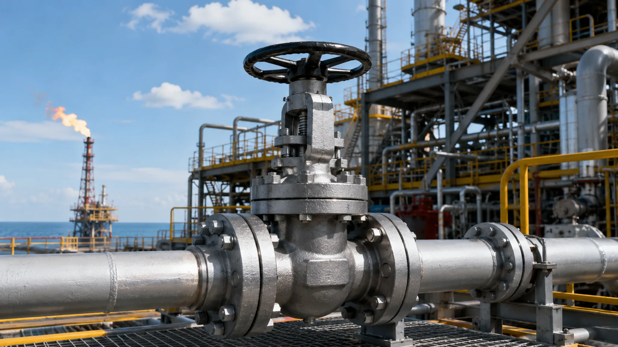
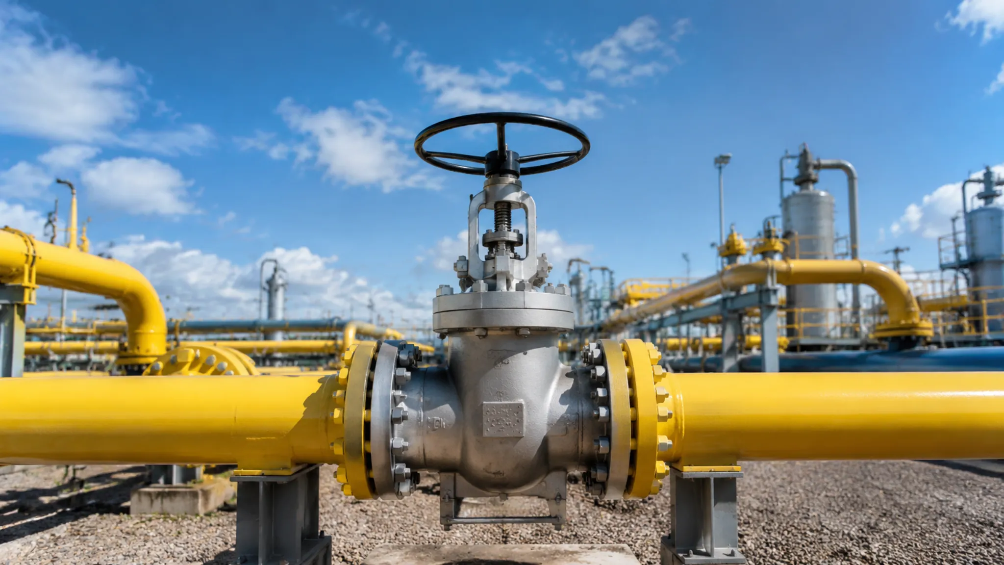
Industrial ball valves for oil and gas pipelines can withstand pressures of up to 10,000 PSI.
The handle must be turned smoothly through 90 degrees to prevent water hammer in the pipeline system.
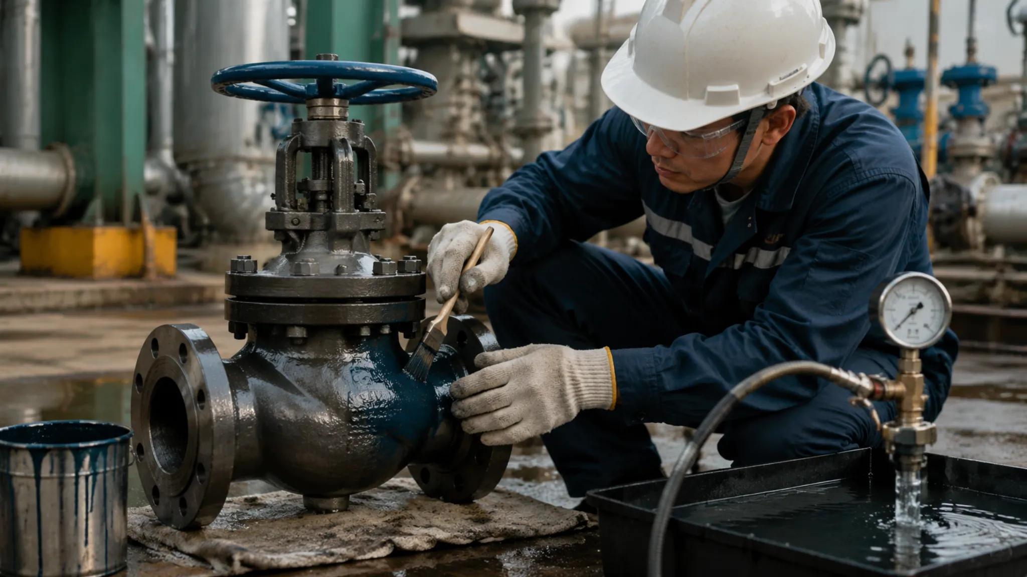
For operational safety, the valve uses an anti-blowout stem design and complies with API 607 fire-safe standards.
If a fire destroys the non-metal soft seat, the secondary metal seat will quickly seal against the ball, effectively stopping high-pressure oil and gas leakage.
High Pressure
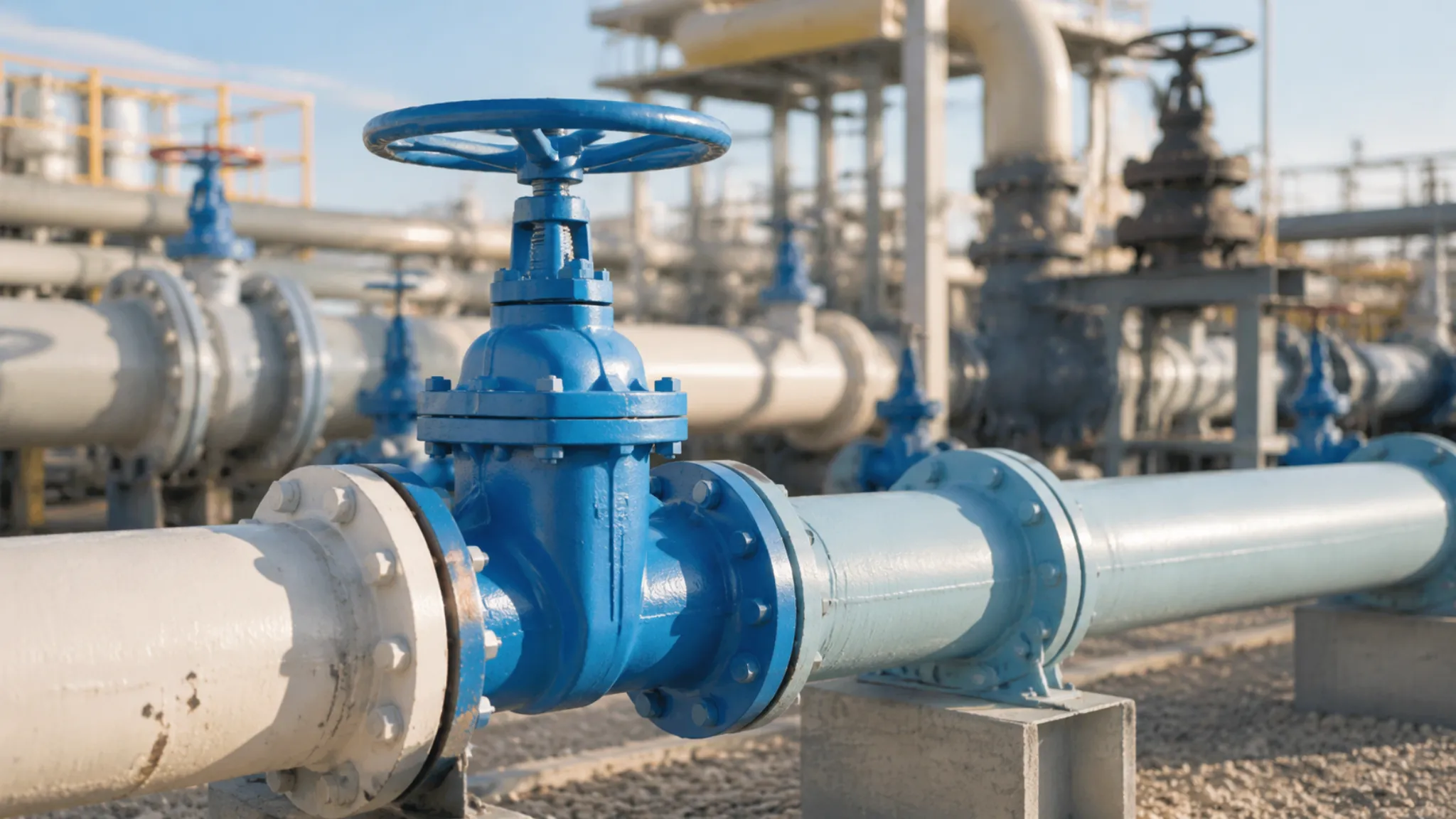
High-pressure pipeline ball valves are rated for ASME Class 900 to 2500 service.
Under API 6D, the valve body must withstand a hydrostatic test at 1.5 times its rated pressure.
In natural gas export pipelines in the Permian Basin, normal operating pressure typically stays between 10.3 MPa (1,500 psi) and 14.8 MPa (2,150 psi).
When the line size reaches 42 inches, the one-way axial thrust acting on a trunnion-mounted ball can exceed 500 tons.
Engineering projects typically use ASTM A105 or A350 LF2 forged steel to build split-body valve housings, with a minimum wall thickness of 85 mm to resist long-distance pipeline stress and the expansion load of the internal medium.
Trunnion Support
On the 48-inch Trans-Alaska crude oil pipeline, winter temperatures often fall below -40°C, while daily operating pressure inside the line remains around 1,180 psi. Under those conditions, the force pushing against a closed ball approaches 1,500 tons. In a standard floating ball valve, that massive one-way thrust would drive the ball straight into the downstream PTFE soft seat, instantly crushing the seal and shutting down the entire line.
To absorb that 1,500-ton destructive load, engineers add high-strength forged cylindrical shafts—trunnions—to the top and bottom of the ball and lock them firmly into bearing supports inside the valve body. The enormous fluid-induced thrust is transferred entirely into these two oversized metal shafts. As a result, the upstream and downstream seats only need to carry the initial spring preload.
The hardware supporting this system is governed by strict engineering specifications:
- Upper journal size: Under API 6D, the upper trunnion diameter for a 48-inch ball typically reaches 350 mm.
- Pressure-bearing material: 17-4PH precipitation-hardening stainless steel is used, with yield strength above 1,000 MPa.
- Surface reinforcement: The journal surface is coated with a 0.15 mm layer of tungsten carbide to resist severe friction.
- Assembly process: The fit tolerance between shaft and bearing is tightly controlled at 0.05 to 0.08 mm, and the lower support plate must be press-fitted using 50-ton hydraulic equipment.
With tolerances that tight, ultra-low-friction bearings are essential. Many valves used in North American gas transmission systems are fitted with metal-backed DU plain bearings. These use a steel shell with a porous bronze sintered layer and a surface layer of PTFE and lead. This self-lubricating design delivers a friction coefficient of only 0.04 to 0.06.
Thanks to that extremely low friction, even under Class 1500 pressure conditions, a solid 8-ton ball can still be rotated smoothly through 90 degrees by a pneumatic actuator with less than 90,000 N·m of torque. In harsh environments such as Saudi Arabia’s Ghawar oilfield, where high chloride concentrations and trace hydrogen sulfide are present, the lower support trunnion is replaced with Inconel 625 nickel alloy to prevent intergranular corrosion.
In Italian manufacturing plants, these metal parts—often weighing over ten tons—are assembled in temperature-controlled workshops maintained at 20°C to eliminate dimensional error caused by thermal expansion and contraction. Operators use CNC vertical lathes to precision-grind the outer surface of the ball, and roundness error is strictly limited to less than 0.02 mm.
Before shipment, the finished valve is sent to an underground pressure-testing bunker, where the cavity is filled with pure water containing a rust inhibitor. During the test, pressure is raised to 1.5 times the rated value and held for 120 minutes, while acoustic sensors mounted on the exterior monitor for high-frequency leakage noise. After passing inspection, the valve is coated with a 300-micron zinc-rich epoxy primer and loaded onto a flatbed trailer for transport to the Port of Houston.
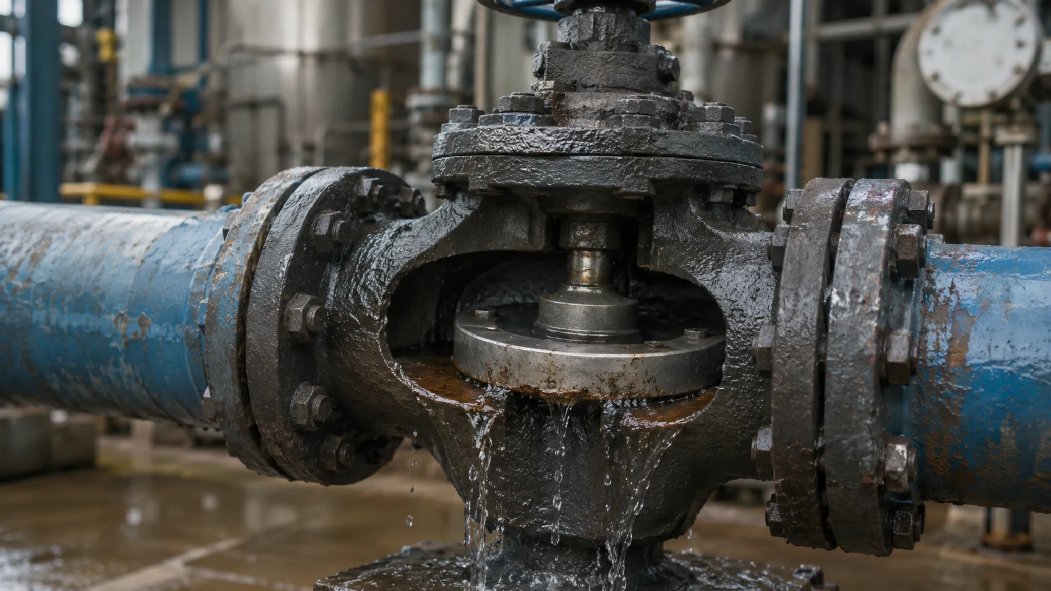
Metal-to-Metal Sealing
At the Thunder Horse deepwater platform in the Gulf of Mexico, wellhead operating pressure remains around 15,000 psi. The produced crude contains a high concentration of quartz sand. Under that extreme pressure differential and severe abrasion, PTFE soft seats cannot survive more than 72 hours before they plastically deform and tear apart.
In the field, engineers remove the damaged soft seals and replace them with all-metal sealing components as the fluid barrier. The seat ring base is forged from ASTM A182 F51 duplex stainless steel, raising its yield strength above 450 MPa. Bare stainless steel surfaces cannot endure prolonged sand erosion, so surface hardening is mandatory.
In valve manufacturing workshops in Texas, robotic arms carry out HVOF (High Velocity Oxygen Fuel) spraying. Aviation kerosene and high-purity oxygen burn together to generate a 3,000°C flame stream, which propels tungsten carbide (WC) powder at Mach 2.5 onto the ball and seat surfaces.
The powder particles flatten instantly on impact and form a dense mechanically interlocked coating on the metal substrate. The tungsten carbide layer is controlled within a physical thickness of 0.25 to 0.35 mm. Its internal porosity is forced below 0.5%, cutting off the corrosion path through which high-pressure sour gas could otherwise penetrate the base material.
| Coating Chemistry | Spray / Overlay Process | Rockwell Hardness | Applicable Pipeline Scenario | Coating Porosity |
|---|---|---|---|---|
| Tungsten Carbide (WC-Co) | HVOF | 68–72 HRC | Canadian oil sands pipelines with heavy quartz sand abrasion | < 0.5% |
| Chromium Carbide (Cr3C2-NiCr) | HVOF | 60–65 HRC | North Sea high-pressure, high-temperature sour gas wellheads (350°C) | < 0.8% |
| Stellite 6 | PTA Plasma Powder Welding | 40–45 HRC | High-pressure, strongly acidic crude service in Alaska pipelines | 0% (fully metallurgically bonded) |
Once spraying is complete, the cooled tungsten carbide surface is as rough as sandpaper. A CNC grinder fitted with a diamond wheel begins rough grinding to remove excess material. The geometric deviation of the ball’s outer diameter is quickly corrected to within 0.05 mm.
The ball and the two metal seats must achieve an exceptionally high level of physical contact. These three critical parts are then sent to a matching grinder, where technicians apply lapping compound containing 3-micron diamond particles. The machine simulates actual valve opening and closing, running continuously at 15 rpm.
The lapping process takes 48 to 72 hours. A continuous, uniform bright band gradually appears on the contact surfaces of the ball and seats. The final metal surface roughness is polished to Ra 0.05 μm. In a dark room, if a strong flashlight is shone from one side of the sealing band, no light can be seen from the other side.
Once 100% contact is achieved, engineers install 36 cylindrical coil springs made of Inconel 718 behind the metal seat. With the pipeline at zero pressure, the spring pack provides more than 3 tons of static thrust, pressing the metal seat tightly against the ball surface.
When crude carrying large amounts of debris flows through the valve cavity, the sharp edge of the metal seat acts like a physical scraper. Each time the ball rotates 90 degrees to close, the hardened lip strips asphalt chunks and sand particles off the ball surface like a razor. Even at 68 HRC, the surface shows no scratches.
Subsea pipelines in the Troll gas field in the North Sea occasionally experience thermal surges of up to 200°C. Because the massive ball and the thinner seat ring expand at different rates, engineers calculate that a solid 36-inch ball will expand in diameter by about 1.2 mm when the temperature differential reaches 150°C.
The disc spring stack behind the seat is designed with a precise 1.5 mm compression travel to absorb that movement. The spring chamber is filled with high-temperature molybdenum disulfide grease. When temperature rises sharply, the seat moves backward to accommodate ball expansion, then returns under a 5,000-pound spring rebound force after cooling, restoring tight contact.
Saudi Aramco’s gas processing facilities have subjected this structure to destructive limit testing. In gas pipelines containing 10% H2S, the valve is exposed for extended periods to a one-way differential pressure of 10.3 MPa. After 1,500 full-load open-close cycles, the assembly is disassembled and sent to a test chamber for high-pressure nitrogen leakage testing.
Both ends of the test section are filled with pure nitrogen at 15,000 psi, and the pressure drop is monitored for 15 minutes. Under API 598, the acceptable leak rate is defined as zero bubbles per minute. The instrument readout shows an absolute zero.
This ultra-dense metal sealing system dramatically increases the torque required to operate the valve. A 36-inch metal-seated high-pressure ball valve requires a heavy-duty gas-over-oil actuator capable of delivering 150,000 N·m of breakaway torque. The gas supply is taken directly from the pipeline’s own high-pressure natural gas, eliminating the need for separate cabling.
Forged Steel Body Wall Thickness
Gas gathering and transmission systems in Alberta, Canada, operate under extremely low temperatures and high pressure during winter. Internal operating pressure remains around 15 MPa. Early valve bodies made using sand casting suffered brittle fracture in outdoor exposure at -45°C. Deep inside cast metal components, microscopic gas pockets and shrinkage defects cannot be fully eliminated.
High-pressure natural gas can penetrate these microscopic flaws in the casting. Rapid pressure fluctuations in the line then cause localized metal fatigue, tearing open ordinary cast steel bodies with walls 120 mm thick along those microcracks. In North American long-distance transmission lines, cast products have been completely eliminated from ultra-high-pressure sections.
Heavy hydraulic presses apply a 15,000-ton forging load to cylindrical solid steel ingots heated to 1,200°C. Under this intense mechanical compression, the originally loose metal grain structure becomes extremely dense. Manufacturing rules require a forging ratio greater than 4:1.
- Base metal: ASTM A350 LF2 low-temperature carbon steel, with Charpy V-notch impact energy greater than 27 J at -46°C.
- Grain size: Under ASTM E112, the internal grain size must be refined to Grade 7 or finer.
- Yield strength: After quenching and tempering, yield strength is raised to 360 MPa.
- Volumetric inspection: After full cooling, the forging undergoes 100% volumetric ultrasonic testing in accordance with ASME BPVC.
The raw forged blanks coming from CNC shops often weigh more than twice the final product. Heavy vertical boring mills remove excess stock layer by layer and machine the internal flow passage. High-pressure pipeline service imposes strict wall thickness requirements on the weakest sections of the valve body.
Engineers calculate the minimum body thickness using the pressure design equations in the ASME B16.34 appendix. The mandatory input values include operating temperature, flange pressure class, and the allowable stress of the steel itself.
For a 36-inch Class 2500 ball valve designed for pipeline pressure above 42 MPa, the standard formula yields a minimum pressure-bearing wall thickness of 165 mm at the cylindrical mid-body section.
During outer-diameter turning, the tooling intentionally leaves an additional 5 to 8 mm corrosion allowance. Crude produced from subsea fields such as Brent in the North Sea contains certain levels of CO2 and formation brine. Over long-term flow, the fluid creates a weakly acidic internal environment that removes about 0.1 mm of metal per year from the inner wall surface.
This extra physical thickness allows the heavy valve to remain in continuous subsea service for 30 years without shutdown replacement. The left and right end caps of the three-piece forged body are machined with dense concentric flange bolt holes. The 25-ton center body and the two end closures are then brought together in a temperature-controlled assembly shop.
An octagonal ring-joint gasket (RTJ) made of soft iron or 316L stainless steel is installed in the joint groove. Using lifting equipment, workers insert 56 alloy steel stud bolts, each 3.5 inches in diameter, through the flange holes on both end closures. These pressure-retaining studs fully comply with ASTM A193 B7M.
- Bolt length: Each cylindrical stud is about 850 mm long, and each individual piece weighs over 25 kg.
- Tensile loading: Workers use hydraulic bolt tensioners, with pump station pressure set at 1,500 bar.
- Load distribution: All 56 flange positions are tensioned simultaneously, compressing the metal gasket by 0.3 mm.
- Fit-up clearance: After assembly, the measured flange-face gap between the end caps and the main body is less than 0.05 mm.
Once tightening is complete, the assembled forged body is lifted to a hydrostatic explosion-proof test stand. Test hoses fill the cavity with industrial pure water containing corrosion inhibitor, forcing out trapped air. A pneumatic high-pressure water pump then sharply raises the internal fluid pressure.
API 6D requires the body hydrotest to reach 1.5 times the cold working pressure rating. A Class 1500 valve must withstand internal hydrostatic pressure up to 22.5 MPa on the test stand. Once pressure stabilizes, the electronic recorder begins timing the hold period.
During the 120-minute pressure hold, not a single sweat-like droplet is allowed to appear anywhere on the external metal surface, and the pressure gauge reading must show an absolute zero drop.
Inspectors use high-intensity flashlights to visually examine the massive forged shell. Even extremely small physical deformation is picked up in real time by strain gauges attached to the metal surface. Under ultra-high hydrostatic pressure, the 165 mm thick forged steel body expands outward by less than 0.12 mm.
After pressure is released, workers remove the bottom drain plug to empty the cavity. Dry high-pressure compressed air is then used to blow residual moisture out of dead zones inside the body. NDT inspectors carry portable electromagnetic yokes and scan all machined radius transition areas on the outer body surface.
The energized probe creates a strong magnetic field, and fluorescent magnetic particles are sprayed onto the surface. Under UV light in a dark room, no yellow-green fluorescent lines indicating microcracks appear. This forged steel heart, built to seal off extreme pipeline pressure, is then sent into the epoxy coating shop.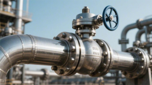
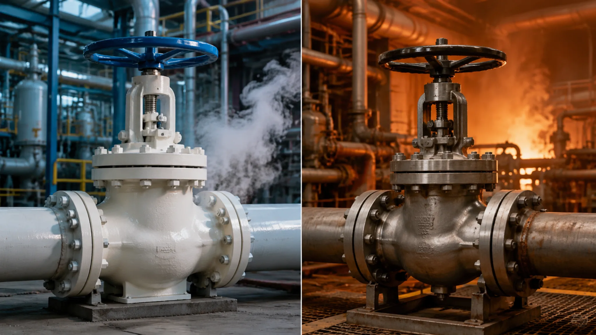
Fire Safe Design
Fire-safe design in industrial ball valves means that after 30 minutes of continuous exposure to external flame at 760°C to 980°C, both internal and external leakage must remain within the very low limits specified by API 607.
Standard PTFE soft sealing materials melt and fail at 327°C. Fire-safe seats use a metal-lip structure. Once the soft seal is destroyed by fire, line pressure pushes the ball against a 316L stainless steel or Inconel metal seat, creating a secondary hard seal.
At the stem area, flexible graphite packing rated for 1,000°C is used.
All leakage data must still pass static pressure testing after cooling to 100°C, ensuring that in fire scenarios on high-pressure lines such as those in the North Sea or the Texas Permian Basin, flammable media such as LNG or crude oil can be fully isolated.
Anti-Blowout Stem
In crude pipelines in the Permian Basin, daily operating pressure is around 10 MPa. If fire breaks out in an oilfield trench, ambient temperature can exceed 800°C within five minutes. The trapped crude inside the valve expands under heat, and internal pressure in a closed 12-inch ball valve can surge beyond 40 MPa.
A forged carbon steel body with 50 mm wall thickness can contain that load. But the metal stem connected to the outside actuator has a much smaller cross-sectional area and becomes the most highly stressed part of the assembly. Under 40 MPa internal pressure, the base of a 50 mm diameter stem is subjected to 78,000 N of upward thrust.
That force is equivalent to the full weight of a heavy truck acting beneath a single component. An ordinary straight stem is held only by external M16 bolts and the gland. In a fire, those bolts soften and stretch under several hundred degrees of heat. The moment the threads fail, 78,000 N can launch the stem out of the bonnet like a bullet.
To prevent this, machinists turn the lower end of the stem so it is significantly wider than the shank itself. A solid ASTM A182 F51 duplex steel bar is machined on a CNC lathe, leaving a robust T-shaped shoulder at the base.
This stepped stem cannot be forced in from the outside. Assembly is done from inside the flow passage upward. A matching chamfered seating surface is machined inside the body, so the shoulder locks against the internal stop face.
The drawing imposes strict machining limits on this retaining interface:
- Clearance between shoulder outer diameter and bore is less than 0.15 mm
- Contact surface roughness is held to Ra 1.6 μm or better
- Chamfer radius at the shoulder base is greater than R2 mm
- Circular runout tolerance does not exceed 0.05 mm
Under normal conditions, a 2 to 3 mm thick PEEK washer sits between the T-shoulder and the body. As crude pressure pushes upward from inside the pipe, the shoulder presses the washer tightly against the inner body surface. The higher the internal pressure, the stronger the mechanical engagement becomes, eliminating the need for any external retaining screw.
In third-party fire tests conducted to API 607, external flame temperature reaches 980°C. The PEEK washer turns to ash at 343°C, leaving a 3 mm gap beneath the stem. The 78,000 N thrust then pushes the stem upward slightly.
At that moment, the metal face above the T-shoulder impacts the internal thrust surface of the body. The entire clearance left by the burned-out washer is eliminated through direct metal-to-metal contact. Crude that would otherwise escape through the gap is trapped inside.
At furnace temperatures of several hundred degrees, the entire packing assembly relies on several materials working together:
- 316L stainless steel provides the rigid metal seating surface
- Inconel 718 springs compensate for 1.5 mm of thermal expansion mismatch
- Pure graphite rings remain dimensionally stable at 1,000°C
- Spiral-wound gaskets hold a preload of 150 MPa
Before shipment, inspectors hydrotest the valve under ASME B16.34. A Class 600 pipeline valve is pressurized with water to 15.3 MPa and held for 15 minutes. Inspectors then loosen all gland nuts and remove the gland entirely.
Even under 15.3 MPa hydrostatic pressure, the stem does not move upward by even half a millimeter, and not one drop of water leaks out. The internal water pressure alone holds the large shoulder firmly against the body wall.
On offshore platforms in the Gulf of Mexico, gas lines run beneath steel grating walkways. Inspectors walk above piping carrying 40 MPa pressure every day. If fire causes the line pressure to spike, the locked shoulder prevents the stem from being ejected, protecting personnel from being struck by a several-hundred-pound metal component.
Maintenance crews routinely verify the following physical data on site:
- 3 to 5 threads of spare stem thread remain visible above the top
- Resistance between the anti-static ball and the body is less than 10 ohms
- Compression loss of the packing gland does not exceed 20% of original thickness
- Actuator torque deviation remains within 15% of rated value
After H1150D heat treatment, 17-4PH stainless steel achieves tensile strength up to 1,000 MPa. Even if the external nameplate and plastic parts are burned away, internal high pressure still keeps the stem securely in position.
Soft-to-Metal Seat Transition
On crude export platforms in the Brent field of the North Sea, the main pipeline carries live crude at 15 MPa. Under normal operation, sealing depends on a white PTFE soft insert clamped between the seat ring and the ball. The steel seat ring compresses a 10 mm thick PTFE insert tightly against the stainless steel ball. Internal pressure together with spring force behind the seat keeps the soft insert in full contact, preventing even a single drop of oil from leaking.
When platform alarms sound and surrounding equipment catches fire, flames engulf the valve body. Ambient temperature rises toward 800°C, and heat conducts into the valve cavity. PTFE reaches its melting point of 327°C and quickly turns into a soft mass, then burns away completely. Once the insert is gone, a physical gap of roughly 3 to 5 mm instantly appears between the steel seat ring and the ball.
The Inconel 718 wave springs behind the seat are already held in a compressed, high-load state. As soon as the soft insert disappears, dozens of springs expand forward. Each spring contributes 450 N of mechanical thrust, driving the 30 kg steel seat ring rapidly toward the ball to close that 5 mm clearance.
At the same time, the 15 MPa crude inside the pipe continues to act on the effective pressure area behind the seat. Fluid thrust and spring force combine to slam the metal seat against the ball in just 0.2 seconds. A 2 mm wide metal lip machined on the front edge of the seat strikes the metal ball surface with force.
The carbon steel ball is finished with a 75 μm electroless nickel plating (ENP), giving it a surface hardness of 500 HV. The metal sealing lip of the seat is made from slightly softer 316L stainless steel. When the two surfaces make contact, the softer lip undergoes slight plastic deformation and conforms to the curvature of the ball, forming a fully metallic sealing barrier.
Hard-on-hard contact cannot achieve the same perfect conformity as a plastic insert. API 607 therefore defines an allowable leakage limit under fire conditions. For a 10-inch Class 600 pipeline valve exposed to 760°C flame for 30 minutes, crude leakage below 400 ml/min is considered compliant.
Third-party laboratories conducting dry-fire tests with natural gas have established the following leakage limits for different valve sizes during the burn period:
| Valve Size (NPS) | Pressure Class | Maximum Internal Leakage at Metal Seat | Maximum External Leakage at Flange |
|---|---|---|---|
| 4 in | 300 | 1,600 ml/min | 100 ml/min |
| 8 in | 600 | 3,200 ml/min | 200 ml/min |
| 16 in | 900 | 6,400 ml/min | 400 ml/min |
| 24 in | 1500 | 9,600 ml/min | 600 ml/min |
The full-metal barrier must survive 30 minutes of intense fire exposure. After the fire is extinguished, emergency water monitors spray the red-hot valve. Within minutes, the body temperature drops from 800°C to below 100°C. Thermal contraction causes a 300 mm diameter steel ball to shrink by about 1.2 mm.
The springs contract together with the seat ring, while the 15 MPa line pressure continues to act on the back-pressure area. That constant force keeps the metal lip fully engaged, compensating for the 1.2 mm thermal contraction. API requires that in the post-fire static pressure test after cooling to 100°C, internal leakage over 5 minutes must not exceed one-tenth of the normal allowable fire-test leakage rate.
In the high-H2S zones of Saudi Arabia’s Ghawar field, the design is even more aggressive. The soft insert is upgraded to high-temperature PEEK with a melting point of 343°C. The ball surface is coated with 0.3 mm of tungsten carbide, reaching 70 HRC. The metal sealing lip is upgraded to F51 duplex steel.
When these two metals—whose hardness differs significantly—impact each other, the lip is forced into a 0.5 mm deep conforming track. Quartz particles carried in the crude bounce off the tungsten carbide surface. Residual incompletely burned PEEK is driven into the metal gap by high-pressure crude. Under 40 MPa pressure, the mixture of residue and metal reduces leakage to less than 50 ml/min.
Maintenance crews use ultrasonic flaw detectors every month to scan behind the seat. The sound waves pass through the 50 mm thick carbon steel body and reflect from the spring cavity, allowing engineers to calculate that fatigue in the Inconel spring pack remains below 15% of total travel. The O-ring in the load-bearing area may already have aged and hardened, but the flexible graphite ring behind it continues to provide the necessary sealing support.
Pipeline operators watch pressure-drop data on the DCS screen. On a 12-inch mainline, upstream gauge pressure reads 10.5 MPa and downstream gauge pressure reads 0.1 MPa. The full 10.4 MPa differential pressure acts on the ball and the 2 mm wide metal lip. The local stress at the sealing lip reaches 120 MPa, still well below the yield limit of 316L steel.
Center Flange Gasket
At Prudhoe Bay in Alaska, polar crude pipelines operate year-round at -40°C, carrying sand-laden crude at 8 MPa. The two forged steel body halves are clamped together by 24 straight-thread ASTM A193 B7 high-strength stud bolts. In engineering terms, the joint between these two semi-cylindrical halves is called the center flange.
The joint contains a dual sealing system. The inner seal is an FKM O-ring with a cross-section of 5.33 mm, while the outer seal is a 4.5 mm thick metal gasket. Under normal operation, the FKM ring holds back the 8 MPa liquid crude, so the outer gasket never sees oil.
If a compressor explodes at a pumping station, flames can spread along the trench. Fire temperature can exceed 760°C within 10 minutes, and heat travels through the 50 mm thick carbon steel body straight into the center flange. The inner FKM O-ring begins to carbonize and become brittle at 200°C.
Once temperature exceeds 300°C, the O-ring is completely burned away. The 8 MPa crude instantly breaks through the inner sealing barrier and rushes toward the outer gasket. That outer gasket is a metal-graphite spiral-wound gasket installed specifically to API 607 requirements. It is literally formed by winding strip materials together under compression.
In the fabrication shop, workers stack and wind two materials together on the flange face:
- A 0.2 mm thick 316L stainless steel V-profile strip provides the structural framework.
- A 0.5 mm thick high-purity flexible graphite strip fills the sealing gaps.
- A 4 mm thick carbon steel outer ring locks the gasket in position.
Before shipment, the 24 B7 studs are tightened with hydraulic wrenches to 850 N·m. The two flange faces compress the 4.5 mm gasket down to 3.2 mm. The stainless steel corrugations are flattened into tiny energy-storing springs, carrying as much as 150 MPa of mechanical preload.
The machined flange-face finish is controlled within Ra 3.2 to 6.3 μm. Under high compression, the flexible graphite is forced into metal surface grooves too small to be seen with the eye. Even under external fire at 900°C, the graphite does not melt; instead, it expands slightly by about 0.1% in volume.
That expanding graphite blocks every microscopic leakage path and keeps the 8 MPa crude trapped inside the valve body. In third-party fire-testing laboratories in Houston, engineers record the performance of this center-flange barrier in accordance with API 6FA.
“For a 16-inch Class 600 trunnion-mounted ball valve exposed to flame at 760°C to 980°C for 30 continuous minutes, external leakage from the center flange must remain below 400 ml/min.”
After more than 20 minutes of fire exposure, the B7 studs holding the flanges together reach nearly 600°C. Thermal expansion stretches the studs by about 0.8 mm, and the tightly clamped flange interface begins to loosen.
At that point, the compressed 3.2 mm gasket starts to react. The elastic energy stored in the stainless steel V-windings pushes the graphite outward. Through its own recovery force, the gasket compensates for the 0.8 mm bolt elongation, and the joint remains tightly sealed.
After the fire is extinguished, high-pressure firefighting water cools the red-hot valve rapidly back to near ambient temperature. Thermal contraction pulls the elongated studs back again, forcing the two flange faces hard against the gasket.
The carbon steel outer ring on the gasket sits at the outermost edge and limits the minimum safe flange spacing. No matter how much the studs contract, the outer ring prevents the graphite and stainless windings from being crushed again under hundreds of tons of compressive force, allowing the gasket to continue holding line pressure.
After a fire, maintenance teams in the North Sea inspect damaged equipment. Workers scan the full circumference of the center flange using a portable hydrocarbon detector. The VOC reading on the instrument remains stable below 50 ppm.
The outer nuts are blackened and heat-damaged, with surface hardness reduced by about 40%, making normal disassembly impossible. Workers cut through all 24 studs one by one using pneumatic cutting tools. After prying open the two half-ton flanges, the internal condition becomes fully visible.
Nothing remains of the inner FKM O-ring except a char mark in the groove. The outer metal-graphite spiral-wound gasket remains completely seated in its machined recess. Its protective coating has fully volatilized, exposing the metallic base color of the 316L stainless steel.
Operational Safety
Under ASME Class 2500 (420 bar) service conditions, the anti-blowout stepped stem can withstand 6,000 pounds of axial thrust.
Low-emission packing qualified to ISO 15848-1 AH can keep methane fugitive leakage below 50 ppm.
An emergency shutdown valve (ESDV) equipped with a spring-return pneumatic actuator can drive a 36-inch valve through a full 90-degree closing stroke in 3 seconds after receiving a trigger signal that meets IEC 61508 SIL 3 requirements.
Dynamic Packing Compression
In ASME Class 1500 pipelines, internal fluid pressure can reach 250 bar. After 500 open-close cycles, the PTFE packing inside the valve is compressed and undergoes a permanent volume loss of 2% to 4%.
Once the packing shrinks, the contact force against the stem drops as well, reducing compression load by roughly 30%. A conventional bolted gland cannot automatically compensate for that loss. In the past, workers at refineries in Houston had to visit the site every three months with a torque wrench and re-tighten the gland nuts to 45 N·m, or natural gas would begin to leak.
Engineers solved this by installing dish-shaped Belleville springs between the gland and the nuts, replacing rigid metal-to-metal loading. Four disc springs with an outer diameter of 40 mm and an inner diameter of 20.4 mm are stacked in two opposing pairs, providing a continuous thrust of 8,500 N.
PTFE is extremely sensitive to temperature, with thermal expansion and contraction about ten times greater than steel. When the gas temperature in the line rises to 200°C, the packing expands. The spring stack is compressed upward by 1.2 mm, absorbing that extra expansion so the stem does not seize.
At night, when ambient temperature falls to -40°C, packing in LNG service contracts. The preloaded disc springs automatically move downward by 0.8 mm, keeping firm force on the packing gland. No matter how packing thickness changes, the contact pressure between the packing and the stem remains above 3,000 psi.
Methane molecules cannot escape through this high-pressure sealing barrier. Using a photoionization instrument under EPA Method 21, inspectors in the United States consistently record fugitive readings below 15 ppmv. In sour environments containing hydrogen sulfide (H2S), material selection becomes especially demanding.
Ordinary 304 stainless steel can crack from chloride attack in less than three months in acid-gas service. Under API 6D, pipeline valves must use materials selected in accordance with NACE MR0175. The following are typical service-life data for common disc spring materials in sour environments:
| Belleville Spring Material | Ultimate Tensile Strength (MPa) | Maximum Service Temperature | Expected Life in H2S Exposure | Relative Procurement Cost |
|---|---|---|---|---|
| 17-7 PH Stainless Steel | 1170 | 315°C | Less than 12 months | 1.0 |
| Inconel 718 | 1034 | 593°C | More than 60 months | 4.5 |
| Elgiloy Alloy | 1930 | 450°C | More than 120 months | 8.2 |
On gas production platforms in the Gulf of Mexico, most pipeline ball valves now use Inconel 718 nickel alloy for the disc springs. Even at 40 HRC, it can still resist pitting from high chloride concentrations in seawater. In laboratory compression tests, its spring force drops by less than 1.5% after 10,000 continuous cycles.
The service life of this dynamic sealing system is also strongly influenced by stem surface roughness. If the stem is too smooth, with Ra below 0.1 μm, grease cannot stay on the surface and the packing fails quickly from dry friction. If roughness exceeds 0.8 μm, the rotating stem behaves like a file and rapidly turns the packing into powder.
In the factory, CNC machinery controls stem surface finish tightly within Ra 0.2 to 0.4 μm. To make the 90-degree turning motion smoother, the stem is also coated with ENP or tungsten carbide. This 75 μm coating reaches 70 HRC in hardness.
Its friction coefficient against graphite packing drops to 0.08. On a 6-inch Class 900 ball valve opening against a 2,000 psi pressure differential, required torque falls from 1,200 N·m to 850 N·m. The packing set uses a five-ring V-configuration.
Braided carbon fiber rings are installed at the top and bottom to contain the softer material and prevent extrusion under pressure. The three PTFE V-rings in the middle are all oriented toward the high-pressure side of the pipeline. When 600 psi natural gas enters the V-grooves, it forces the lips outward, tightening the seal against both body and stem.
At a chemical plant in the Port of Rotterdam, engineers used helium to test leakage against ISO 15848-1 CO3. The valve was placed inside a temperature-controlled chamber cycling between -29°C and 200°C. The ball valve was filled with helium at 40 bar, and a mechanical arm rotated the stem at two revolutions per minute.
Loss of gland bolt preload over time is a normal physical phenomenon. Under ISA-75.19.01, maintenance personnel are required to measure Belleville spring stack height 24 hours after installation, again at 30 days, and again at six months.
When they found the total spring height had changed from 28.5 mm to 29.8 mm, that indicated 1.3 mm of packing wear. The workers then tightened the gland nuts by half a turn clockwise, restoring the height to 28.5 mm. Field records from shale gas pipelines in the Permian Basin show the effect clearly.
During winter blizzards, when ambient temperature dropped to -35°C, a conventional old-style sealed 8-inch ball valve shrank and leaked, triggering detector readings as high as 1,200 ppm. A neighboring valve of the same size, fitted with five stacks of Inconel 718 Belleville springs, used its 6,000-pound reserve thrust to keep external gas leakage below 25 ppm.
SIL 3 Rating
The subsea gas transmission network at the Johan Sverdrup field in the North Sea uses 48-inch fully welded ball valves. Natural gas operating pressure in the line reaches 120 bar. When the Safety Instrumented System (SIS) sends a command to the emergency shutdown valve (ESDV), a single-acting pneumatic actuator responds. Its housing is made of carbon steel, and inside it is a pre-compressed heavy-duty spring pack.
The moment the gas supply is cut off, the springs release 185,000 N·m of torque. The 6-ton trunnion-mounted ball is forced through a full 90-degree shutoff rotation in 3.2 seconds. SIL 3 under IEC 61508 quantifies its requirement down to the fourth decimal place.
In low-demand mode, the average probability of dangerous failure on demand (PFDavg) must be held within the narrow range of 0.0001 to 0.001.
At a refinery in Beaumont, Texas, engineers equipped the actuator gas circuit with a 1oo2 solenoid valve architecture. Two 24 V DC solenoids are mounted side by side on a 316L stainless steel control panel. When one receives a 20 mA de-energizing signal, its vent port exhausts the internal cylinder at 1,200 L/min. This redundant arrangement eliminates the single-point failure path that could otherwise prevent the valve from moving.
On ball valves that remain open for long periods without movement, very high static friction can develop between the PTFE seats and the metal ball. Engineers therefore allow a twofold safety margin in actuator torque calculations. Even at a line differential pressure of 1,500 psi, the spring-end output torque of the actuator still remains 2.2 times higher than the valve’s actual break-to-open torque (BTO). Field operators have introduced partial stroke testing (PST).
This allows testing without shutting down the entire ASME Class 600 crude pipeline. The intelligent valve positioner releases a small amount of compressed air to the actuator. The stem slowly rotates 15 degrees, pauses for 2 seconds, then returns to the full-open position.
A 15-degree partial movement reduces effective line area only slightly, with flow dropping by less than 4%, which is too small to create any noticeable pressure disturbance for downstream centrifugal pumps.
The test report records the startup air pressure at the instant the valve first breaks free from static friction. In a DNV-certified report from the Alaska pipeline last month, the startup pressure of a 36-inch ball valve had increased from 5.2 bar to 5.8 bar. The maintenance team then went to site with grease guns and injected molybdenum disulfide lubricant into the stem bearings.
After another PST the next day, the pressure dropped back to a normal 5.1 bar. The risk of mechanical sticking was eliminated before the valve seized completely. Winter temperatures in Fort McMurray, Canada, can fall to -46°C. Standard FKM O-rings inside actuators harden at such low temperatures and lose their elastic sealing ability.
- The pneumatic motor is upgraded with low-temperature VMQ silicone seals.
- The guide rings are machined from carbon-fiber-filled PTFE.
- After 72 hours in a -50°C temperature-controlled room, power to the solenoid is cut off.
Even under those conditions, the cylinder can still fully vent in 2.8 seconds. Fire conditions test the survivability of the entire shutdown assembly. Under API 607 fire testing, the pipeline ball valve must remain exposed to 1,000°C fire for a full 30 minutes. The pneumatic actuator is protected externally by a 50 mm thick ceramic-fiber fireproofing jacket.
Even when ambient temperature reaches 1,100°C, the surface temperature of the cylinder beneath the jacket is held below 80°C. The carbon steel spring pack inside does not lose strength through annealing. All 3/8-inch control tubing connected to the cylinder is replaced with Incoloy 825 alloy tubing instead of standard 304 stainless steel. Compression fittings are tightened to 65 N·m with a torque wrench.
After the fire test, 6 bar instrument air is introduced, and the entire pneumatic circuit remains bubble-tight. Two independent explosion-proof fiber-optic cables run between the safety PLC in the control room and the field ball valve. The cables are buried 2 meters underground in the pipe trench and protected by corrugated metal conduit. Loop impedance is strictly controlled below 250 ohms.
Every 50 milliseconds, the PLC sends a pulse diagnostic signal to the field. If an excavator cuts one of the lines, the standby cable takes over command transmission within 10 milliseconds. This fully SIL 3-compliant combination of mechanical and electronic control circuits reduces the probability of human operating error to an extremely low level.
Saudi Aramco has fitted 120 high-pressure pipeline ball valves in the Ghawar field with this pneumatic system. Over five years of operation and a cumulative 5 million service hours, not a single failure-to-operate incident has occurred. When the operator presses the red ESD button in the main control room, all heavy-duty field valves move to the fully closed position within the specified time window.

")