
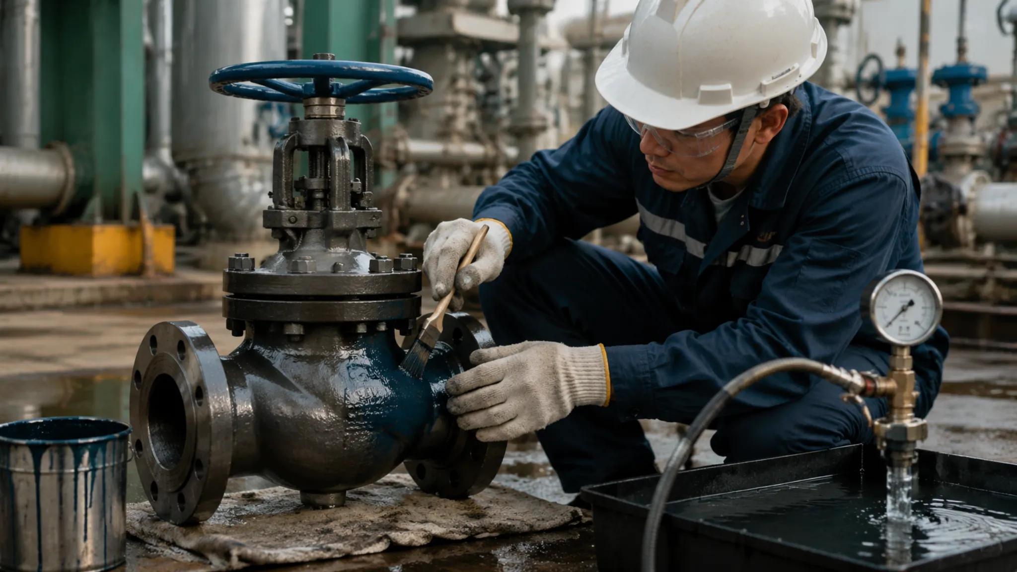
For extreme high-pressure service, a forged steel F316L trunnion-mounted ball valve is the preferred choice to withstand ultimate pressures up to 10,000 PSI.
The sealing system should use a PEEK seat paired with a tungsten carbide coating to ensure zero leakage under a 400 bar differential pressure.
A gear operator must be used for slow opening and closing to prevent water hammer, and 100,000-cycle pressurized actuation test data should be verified to ensure long-term service life.
Sealing Performance
High-Pressure Conditions
In subsea pipelines 3,000 meters below the Gulf of Mexico, heavy crude loaded with large amounts of quartz sand flows continuously through the line. Internal pressure can reach a staggering 15,000 PSI, roughly equivalent to balancing the weight of a small car on the area of a fingernail.
The surrounding seawater stays at 2 to 4°C year-round, while the pipe wall is repeatedly hit by crude oil at 130°C. That severe temperature differential causes the thick steel to expand and contract every day in ways the naked eye cannot see.
A standard PTFE gasket would not survive even five minutes in this environment. Under hundreds of tons of pressure, it would deform like chewing gum and extrude past the edge of the steel flange.
For deep-sea ball valves, the seat base is upgraded to duplex stainless steel F51, a material with an impressive tensile strength of 620 MPa.
Inside that rigid base sits an extremely thin high-performance PEEK ring. Only 0.5 mm protrudes above the metal surface. Any more would be crushed instantly under pressure; any less would fail to seal against the ball.
The machining center must hold the dimensional tolerance of that sealing groove within ±0.02 mm, roughly one quarter of the diameter of a human hair.
- Workshop temperature is kept constant at 22°C
- Cutting feed rate is set at 0.05 mm per revolution
- Measurements are taken with a coordinate measuring machine
- Surface finish must reach Ra 0.4 μm
A hydraulic motor delivers 12,000 N·m of torque to rotate a two-ton ball, and at that scale, friction becomes intensely destructive.
Sharp-edged quartz particles scour the sealing surface at 15 m/s. A pure plastic seat would already have been ground into invisible powder and flushed away by the flow.
To solve this, engineers apply a tungsten carbide coating to the surface of the solid stainless steel ball using HVOF spraying. This gray protective layer is only about 0.3 mm thick, yet its hardness reaches HRC 72, enough to scratch bulletproof glass.
But a hard ball and an equally hard metal seat alone are not enough to stop high-pressure media. The two components must undergo a matching lapping process that lasts 48 hours.
Workers spread a gray-black lapping compound across the contact surface and use a pneumatic actuator to simulate normal opening and closing cycles, rubbing the parts together tens of thousands of times.
- 400-grit diamond abrasive for rough lapping
- 1000-grit abrasive for semi-finishing
- 3000-grit diamond paste for final lapping
- Contact ratio must exceed 95%
After lapping, the two metal contact surfaces become mirror-like, with almost no dead angles. The fit is so precise that even a water droplet as small as 0.005 mm cannot pass through.
Leak testing no longer relies on watching for water droplets. The factory uses high-pressure helium instead. The fully assembled ball valve is placed inside a sealed vacuum chamber, and helium is pressurized into the pipeline cavity.
Helium atoms are only 0.26 nanometers in diameter and are extremely penetrating. A probe scans repeatedly along both ends of the valve body, searching for any escaping molecules.
If the mass spectrometer shows a leak rate higher than one hundred-thousandth of a cubic centimeter per second (1.0E-5 cc/sec), the entire five-ton valve—worth USD 200,000—must be disassembled and rebuilt from scratch.
Even when the process fluid is fully blocked inside the line, the area where the stem exits the body remains the most vulnerable escape path for high-pressure gas. The valve stem rotates dozens of times a day to regulate flow, and repeated metal friction gradually opens fatigue gaps in the packing material.
The stuffing box is packed with five alternating rings of flexible graphite. The three middle rings have a density of 1.4 g/cm³ and mainly absorb radial expansion pressure.
The two outer graphite rings are reinforced with ultra-fine stainless steel mesh, raising their density to 1.6 g/cm³. Workers then tighten the hex bolts to 150 N·m with a torque wrench, compressing the graphite firmly around the stem.
This arrangement can hold gas securely inside the valve body under Class 2500 pressure ratings, or roughly 42 MPa.
In refinery lines handling hydrogen sulfide, operating pressure often rises to 20 MPa. At just 10 ppm, H₂S gives off a strong, offensive smell; at 800 ppm, inhalation can stop breathing within minutes.
That is why 4 or 6 disc springs are stacked in a specific opposing sequence on the gland bolts, providing about 3,000 pounds of continuous preload.
- Spring material: 50CrVA spring steel
- Surface treatment: zinc-plated for corrosion resistance
- Pre-compression: 2.5 mm
- Fatigue life: over 100,000 cycles
As the graphite rings gradually wear down by 0.1 mm over time, the springs extend automatically and fill the newly formed micro-gaps.
Another hidden danger appears once both ends of the pipeline are sealed by the valve: the residual liquid trapped in the cavity between them. Under desert sun, cavity temperature can rise from 25°C to 60°C, and the crude oil inside expands violently.
Based on the liquid’s volumetric expansion coefficient, internal hydraulic pressure can rise by 75 PSI for every 1°C increase. In less than an hour, pressure can exceed the yield strength of the cast steel body.
Even a 50 mm-thick carbon steel shell can split under that force. To prevent this, an Inconel X-750 spring hidden behind the seat takes over the pressure-relief function.
When cavity pressure exceeds upstream line pressure by about 100 PSI, the spring compresses backward by 1 to 2 mm. That tiny movement is enough to let a few drops of crude oil escape back into the upstream line.
Within 0.1 second, cavity pressure drops back below the safe threshold. The drawing imposes extremely tight tolerances on the number of coils and wire diameter of this 20 mm outside-diameter spring. Even half a turn less would shift the pressure-relief point by dozens of PSI.
Sealing Materials
The nonstick coating used in household cookware is PTFE, known in chemical plants by the same name. A 15 mm-thick PTFE sealing ring inside an industrial valve is more than adequate for low-pressure water lines around 150 PSI.
Once pressure exceeds 1,000 PSI, problems begin. The white plastic ring deforms like flattened putty and starts to extrude outward. In just one month, it can lose 2.3 mm of thickness.
Once thinned, the seat can no longer conform to the stainless steel ball, and hundreds of tons of water can blast through the microscopic gap.
For 3,000 PSI long-distance natural gas pipelines, the specified material on the purchase order changes to Devlon V-API.
Under a microscope, Devlon’s molecular structure looks as tightly woven as steel mesh. Under a compressive load of 4,000 pounds, its volumetric deformation remains strictly below 1.2%.
Workers machine the nylon stock into a 400 mm diameter ring and install it in a five-ton mainline gas valve. Since natural gas pipelines often contain trace underground moisture, Devlon’s water absorption must be strictly controlled at 0.1%.
If water absorption increases by just 0.5%, the entire nylon ring can swell in the darkness of an underground pipeline, expanding enough to seize the metal ball like a vise.
Even when the pneumatic actuator is supplied with 8 bar of drive pressure, the jammed ball may not move at all.
When process temperature exceeds 150°C, Devlon softens rapidly and fails. At that point, tan-colored PEEK takes over.
If PEEK is boiled in 260°C heat-transfer oil for three full days, then measured with a caliper, the change in outer diameter remains under 0.05 mm.
PEEK is widely favored in aerospace because its benzene-ring molecular structure gives it tensile strength up to 100 MPa.
In 10,000 PSI deepwater wellhead service, PEEK rings replace bulky metal parts and still withstand severe abrasion from subsea sediment.
Machining PEEK is like cutting bone. The tooling must be upgraded to expensive polycrystalline diamond inserts.
Spindle speed is reduced to 500 rpm, and workers carefully control cutting speed to avoid overheating and scorching the chips generated during machining.
Below is a test sheet summarizing the physical performance of common sealing materials:
| Sealing Material | Maximum Service Temperature | Tested Tensile Strength | Pressure Limit |
|---|---|---|---|
| PTFE | 200°C | 25 MPa | 1,000 PSI |
| Devlon Nylon | 150°C | 80 MPa | 6,000 PSI |
| PEEK | 260°C | 100 MPa | 15,000 PSI |
| Tungsten Carbide Surface Coating | Above 400°C | Bond Strength > 70 MPa | Not limited |
In coal chemical projects, black-water pipelines may carry media containing 60% hard coal powder and slag. In that environment, all plastics, nylon, and even PEEK can be shredded within 10 minutes.
Only metal can resist that kind of metallic abrasion. Workers fill the groove on the valve seat surface with a cobalt-based Stellite 6 hardfacing layer using plasma cladding.
The plasma arc reaches 15,000°C. Stellite alloy powder melts into liquid form and fuses to the stainless steel substrate, with the hardfacing layer controlled between 2.5 and 3 mm thick.
After cooling, a Rockwell hardness tester drives its tungsten probe into the surface and produces a stable HRC 45 reading. Coal particles striking the cladding leave only faint white marks and cannot even break through 0.01 mm of the surface.
If the medium changes to nitric acid mixed with quartz sand, Stellite’s corrosion resistance quickly collapses. At that point, HVOF equipment is used to spray tungsten carbide powder onto the ball surface.
Aviation kerosene and oxygen combust violently inside the spray gun. The hot gas propels tungsten carbide particles at 800 m/s onto the surface of a two-ton solid ball.
The particles hit so fast that they flatten under kinetic impact before fully melting, interlocking layer by layer. Internal porosity in the coating is forced below 0.5%.
Under magnification, the 0.3 mm-thick gray protective coating shows no capillary paths for acid penetration. Even after 30 days of exposure to hot 50% nitric acid, the ball surface shows no rust spot larger than the tip of a needle.
Quality inspectors then use an ultrasonic thickness gauge to check 100 random points across the surface of a 600 mm diameter ball. The difference between the thinnest and thickest points remains under 0.02 mm.
To protect against refinery fire scenarios, engineers place a pure black flexible graphite fire-safe ring in a hidden groove behind the PEEK seat.
If a major plant fire drives the surrounding air temperature above 1,000°C within 5 minutes, the PEEK seat can burn to ash, leaving a sealing gap as wide as 3 mm.
Body Strength
Manufacturing Process
An 800 kg cylindrical billet of ASTM A105 carbon steel is loaded into a natural-gas heating furnace. The furnace is held at 1,150°C, and the metal remains there for four hours until the surface turns bright orange and fully workable.
The heated billet is then removed with clamps and transferred to the table of an 8,000-ton open-die forging hydraulic press. With each heavy blow, the hammer strikes the surface at several meters per second.
Each impact compresses the billet by more than 15% in thickness. Coarse dendritic grains inside the metal are crushed, and the finer particles are forced to realign along the direction of stress.
This produces a continuous and dense metal flow line. When an ultrasonic flaw detector scans the forged valve-body blank, the reflected waveform on the screen appears almost perfectly flat.
Internal porosity has already been reduced to below 0.001%. When a tensile specimen is pulled to failure, the dial locks at 510 MPa, exceeding the required minimum of 485 MPa.
In the casting shop, ASTM A216 WCB cast steel is melted in a furnace to 1,560°C. Workers pour the molten steel into a sand mold made from silica sand and resin.
For large ball valve bodies with a nominal diameter of 1,000 mm, size exceeds the practical range of forging. The hot steel must then cool and solidify naturally inside the mold over 48 hours.
As the metal changes from liquid to solid, it shrinks in volume. If the riser dimensions are off by as little as 5 mm, micro-shrinkage cavities can form at the center of the valve wall.
Radiographic testing serves as the caliper for detecting blowholes and porosity. The operator places an Iridium-192 source into the valve cavity, with high-resolution industrial film positioned tightly on the outside.
After a 15-minute exposure, the developed film is placed under a bright viewing lamp for inspection. Acceptance criteria are clearly defined in Appendix B of ASME B16.34.
If a dark spot larger than 2.5 mm appears on the film, the defect must be repaired through a mandatory sequence:
- Grind the area with an angle grinder
- Gouge out the defect by carbon arc air gouging
- Refill the cavity with GTAW weld metal
- Replace the film and repeat radiographic testing
- Record the repair coordinates for documentation
Fully welded ball valves are widely used in long-distance natural gas pipelines. Their bodies are assembled from 3 to 5 forged sections, each up to 50 mm thick.
A submerged arc welding machine travels steadily along the V-groove. Welding wire feeds in at 800 mm per minute, while 28 volts and 600 amps melt the base metal and flux into a liquid weld pool.
Heat input is strictly limited to 2.5 kJ/mm. If it goes higher, the heat-affected zone can develop abnormally coarse grains, reducing room-temperature impact toughness below 20 J.
After welding, the entire valve body is moved into a trolley-type annealing furnace for post-weld heat treatment. The furnace temperature rises slowly at 50°C per hour until reaching 620°C.
The soak time is set at two and a half hours to release the residual stress built up during welding. The valve body then cools naturally in the furnace to 300°C before being removed by crane.
A portable tester is pressed against the weld area, and Rockwell hardness is verified to remain within HRC 22, preventing the metallurgical conditions that can trigger sulfide stress cracking in high-pressure H₂S service.
A CNC horizontal boring and milling machine is used to machine the internal installation step for the sealing components. Feed is controlled precisely at 0.02 mm, about one third of a hair’s diameter.
When a ruby stylus from a surface roughness tester moves across the machined face, the display reads Ra 1.6 μm. This smooth metal surface protects the PEEK seat from long-term damage caused by tiny burrs during operation.
An ultrasonic thickness gauge is then used across a 10 cm measurement grid on the outside of the valve body. Each thickness reading is transmitted in real time to the quality control terminal.
For an 8-inch Class 1500 ball valve body, the measured minimum wall thickness is 41.3 mm, and machining error remains fully within the positive tolerance zone.
On the hydrostatic test bench, a three-cylinder high-pressure plunger pump fills the assembled valve cavity with room-temperature purified water containing 1% water-based rust inhibitor.
Pressure rises steadily to 38.8 MPa over 3 minutes. Holding an 800-lumen flashlight, the inspector checks every inch of the metal surface for signs of leakage.
To pass the final body strength test, the acceptance criteria are severe:
- Flange sealing faces must remain dry, with no droplets
- The gland area around the stuffing box must show no dampness
- The valve body must show no visible macro-deformation
- The mechanical pressure gauge needle must remain perfectly steady
After 120 seconds of pressure holding, the pneumatic dump valve opens instantly. As the high-pressure water roars into the recovery tank, the metal shell—now fully qualified—is tagged for shipment.
Material Grades
ASTM A105 carbon steel is extremely common in standard pipelines, with carbon content limited to a maximum of 0.35%. In lines carrying ambient water or non-corrosive crude oil, it can safely withstand 25 MPa, and wall loss over ten years remains below 0.5 mm.
But in North Dakota oilfields, winter temperatures can plunge to -40°C. At that point, A105 carbon steel becomes brittle like glass. In a Charpy V-notch test, just 15 J can break it instantly.
For that reason, engineers shift to ASTM A350 LF2 low-temperature carbon steel. About 0.4% nickel is added during steelmaking, followed by normalizing at 900°C. Even at -46°C, it can still absorb more than 27 J without fracturing.
Offshore platforms face a completely different kind of attack. Seawater mixed with high chloride concentration can pit ordinary carbon steel into a honeycomb pattern within a few months.
That is where 316L ultra-low-carbon stainless steel comes in. During refining, carbon content is driven below 0.03%, while chromium accounts for around 16%, forming a dense oxide layer only a few nanometers thick on the metal surface.
In chemical plants, 316L valve bodies can serve continuously for 80,000 hours in nitric acid lines running at 150°C. When checked by ultrasonic thickness gauge, the wall is only slightly thinner than the original 12.5 mm.
Natural gas production in the Persian Gulf often involves highly toxic hydrogen sulfide. Under high tensile stress, even standard stainless steel can develop microcracks along grain boundaries, leading to catastrophic failure in under 72 hours.
To address that, metallurgists turn to duplex stainless steel UNS S32205. Its microstructure is half austenite and half ferrite, and its yield strength reaches 450 MPa—roughly double that of 316L.
When extraction depth reaches 3,000 meters below sea level and pressure climbs to 69 MPa, super duplex S32750 becomes the material of choice for high-pressure valves.
The lab report shows molybdenum content raised to 4%, with nitrogen at 0.3%. The calculated pitting resistance equivalent number consistently exceeds 42.
Below is a table extracted from actual factory test records showing mechanical and corrosion-related performance of typical valve body materials:
| Material Marking | Ultimate Tensile Strength | Yield Strength | Minimum Service Temperature | Chloride Resistance |
|---|---|---|---|---|
| A105 (forged carbon steel) | 485 MPa | 250 MPa | -29°C | Very weak |
| LF2 (low-temperature steel) | 485 MPa | 250 MPa | -46°C | Very weak |
| F316L (stainless steel) | 485 MPa | 170 MPa | -196°C | Moderate |
| F51 (duplex stainless steel) | 620 MPa | 450 MPa | -50°C | Excellent |
| F53 (super duplex stainless steel) | 795 MPa | 550 MPa | -50°C | Outstanding |
The purchase price of F53 super duplex steel is often more than 15 times that of standard A105 carbon steel.
In alkylation units handling hydrofluoric acid, even super duplex cannot withstand a medium capable of dissolving glass. In those cases, the material box on the drawing is changed to Monel 400.
This nickel-copper alloy contains about 63% nickel and 28% copper. In highly toxic hydrofluoric acid above 80% concentration, its corrosion rate remains below 0.025 mm per year.
Valve bodies used on deepwater Christmas trees are expected to operate maintenance-free for 25 years. That is where Inconel 625 forms the last line of defense, with 58% nickel, 20% chromium, and 9% molybdenum creating an exceptionally stable atomic structure.
Even at 600°C and under ultra-high pressure, Inconel 625 can still maintain tensile strength above 827 MPa. Yet machining it is extremely difficult—despite coated carbide tools, the cutter often has to be changed every 30 minutes.
Material grade is never just a string of letters on paper. In refineries, workers can often judge an old pipe’s material by the shape and color of the sparks produced during grinding.
The higher the carbon content, the more the sparks burst into bright fox-tail patterns. Stainless steel, by contrast, produces dark red straight sparks with no branching.
At incoming inspection, a PMI handheld spectrometer is pressed against the flange of an F51 valve body fresh from delivery. Once triggered, X-rays penetrate the metal surface.
Three seconds later, the screen shows the composition: chromium 22.5%, nickel 5.8%, molybdenum 3.2%. If any element is off by just 0.1%, the entire batch of forged metal—often weighing dozens of tons—can be rejected.
Wall Thickness & Pressure Capacity
On the engineer’s desk lies an ASME B16.34 handbook hundreds of pages thick. Using a calculator, the engineer plugs extreme operating values into the standard’s minimum wall thickness formulas.
Suppose the nominal size is set at 12 inches and the medium is liquid ethane at ambient temperature. The pipeline’s rated operating pressure is 15.3 MPa, corresponding to ASME Class 900.
Allowable material stress is strictly limited to 137.9 MPa. Based on the formula, the theoretical minimum wall thickness for this carbon steel ball valve body comes out to 31.8 mm. But when the machining order is issued, that figure is quietly increased to 35 mm.
The extra 3.2 mm is reserved as corrosion allowance for the next twenty years of service. An ultrasonic thickness gauge is applied to the newly machined metal surface with couplant gel.
“If the measured thickness at any pressure-containing boundary is even 0.1 mm below the minimum specified on the drawing, this several-ton steel body is nothing more than scrap.”
When the pipeline is transporting high-pressure natural gas at full flow, the heavy ball is pushed into the closed position by the mechanism. The fluid’s kinetic energy impacts the ball surface and generates an enormous blind force.
For a 24-inch ball valve, the projected ball area in the closed position exceeds 0.29 m². At 10 MPa line pressure, the total thrust reaches 290 tons, forcing the ball hard against the downstream metal seat.
That immense load must be carried not only by the thick steel body, but also by the heavy bolts tying both ends of the valve together. ASTM A193 B7 high-strength alloy bolts are tightened to 2,800 N·m with a hydraulic wrench.
Under tensile load, the bolts deform physically. A 400 mm-long fastener can elongate by 0.8 mm while carrying the full 290-ton thrust.
If body wall thickness is insufficient, that same force can cause microscopic expansion of the cylindrical shell.
- Once out-of-roundness exceeds 0.05 mm
- The internal precision metal seat ring begins to warp under load
- Internal leakage can exceed 300 mL per minute
High-pressure lines sometimes produce dull explosive sounds when liquid reverses violently after an unexpected pump stop. Water hammer can drive transient pressure to 2.5 times normal operating pressure in just 0.2 seconds.
A body designed for 15 MPa may be struck instantaneously by 37.5 MPa. If the material’s yield strength cannot absorb that impact, the crystal lattice undergoes permanent plastic deformation.
There may be no visible damage on the outside. But during the next major overhaul, maintenance crews may find that the internal installation step has been crushed by 1.2 mm—enough that even standard spare parts will no longer fit.
To verify how much compressive force those tens of millimeters of steel can really withstand, every high-pressure ball valve must be lifted into an explosion-proof test pit before shipment.
The pump is driven to full output, forcing room-temperature purified water mixed with fluorescent tracer into the sealed valve cavity. The red needle on the pressure gauge rises slowly past the rated line pressure.
API 598 requires the shell strength test pressure to reach 1.5 times the maximum rated working pressure. A Class 1500 ball valve must therefore withstand 38.8 MPa of hydrostatic pressure.
The tester stands behind 2-inch-thick bulletproof glass, watching the steel body in the pit. During the 120-second hold period, the high-pressure water searches for every microscopic crystalline defect.
White test paper is tightly attached all over the outer surface. Once test pressure exceeds 30 MPa, the steel can emit faint metallic groans under extreme stress.
If one area has been machined 2 mm too thin, stress concentration can tear the weak point open instantly. The fluorescent high-pressure water jet will slice through the paper and spray the far wall more than ten meters away.
After the needle holds at 38.8 MPa for a full two minutes, the dump valve releases the water. A coordinate measuring machine then scans the flange again, confirming that all dimensional changes remain fully within the elastic deformation range.
Service Life
Material & Surface Armor
In high-pressure pipelines, fluid velocity often exceeds 15 m/s. Fine sand in the flow acts like countless cutting tools against internal valve surfaces. Standard 316 stainless steel is relatively soft, around HRC 20, and can be deeply scratched, eventually causing leakage.
Field maintenance records show a huge difference in service life once the internal ball is given a protective surface layer. The factory uses HVOF spraying to apply tungsten carbide, raising surface hardness to HRC 65 to 72.
The hard shell does not need to be thick. A controlled thickness of 0.2 to 0.3 mm is sufficient. In high-speed media carrying catalyst powder, this coating improves erosion resistance by 4 to 5 times, allowing 30,000 switching cycles without major overhaul.
Forged duplex stainless steel 2205 components can withstand tensile loads of 450 MPa, far above the 205 MPa typical of conventional 316L.
Duplex steel usually has a pitting resistance equivalent number above 32, which greatly slows corrosion thinning in dirty water containing chlorides.
The spraying process itself is extremely aggressive. The equipment accelerates the powder to 2 to 3 times the speed of sound. Molten particles at roughly 800 m/s slam into the ball surface and consolidate into an exceptionally dense metal-ceramic layer.
- Coating thickness must be controlled between 0.15 and 0.25 mm
- Bond strength tested per ASTM C633 must exceed 70 MPa
- Under a microscope, surface porosity must remain below 0.5%
- Hardness must remain stable between HRC 68 and 72
When two metal components of identical hardness rub against each other under high pressure and frequent cycling, galling becomes likely. Two smooth stainless steel surfaces pressed together under 20 MPa can literally tear material from each other.
That is why the machining drawing requires the ball and seat hardness to differ by 5 to 8 HRC points. Workers hardface the seat with Stellite 6, which contains 27% to 32% chromium and 4% to 6% tungsten.
Even at 600°C, this alloy still maintains hardness above HRC 40. Since fluid composition varies from line to line, the surface armor has to be matched to the service condition.
- Tungsten carbide coating is ideal for sand erosion below 260°C
- Chromium carbide coating handles coal-chemical dry powder up to 850°C
- Stellite alloy is suited for hot, toxic hydrogen sulfide media
- Inconel 625 is used to resist highly saline seawater environments
Workers begin rough grinding with a diamond wheel at 2,000 rpm, spending a full 48 hours bringing the surface to an extremely fine finish.
The part is then inspected on a 3D coordinate measuring machine. A ruby probe circles the ball and confirms that roundness error remains below 0.005 mm.
After machine processing, a skilled technician hand-laps the ball and seat together. The lapping compound contains 3 to 5 μm silicon carbide particles, and the worker pushes back and forth tens of thousands of times with roughly 50 kg of force.
- Surface finish reaches Ra 0.1 μm
- Blue-check contact band forms a full ring wider than 3 mm
- Under magnification, the contact area shows 100% full engagement
- Rated-pressure nitrogen testing produces no bubbles at all
At oil and gas wellheads where pressure can reach 10,000 psi, ordinary coatings may flake off in large patches. In that case, the only reliable solution is to machine the entire trim from a solid Inconel 718 forged piece.
This alloy is first heated to 1,000°C, then held and later reheated around 720°C. After this two-stage heat treatment, tensile strength rises close to 1,375 MPa.
Moist hydrogen sulfide in the line can quietly penetrate metal and cause cracking from within. NACE MR0175 clearly states that metal hardness in sour water service must not exceed the specified limit.
Annealing keeps Inconel 718 within HRC 35 to 40, preserving enough toughness to resist brittle failure from gas ingress.
For LNG lines at -196°C, ordinary carbon steel shatters like glass. Austenitic F316L stainless steel, however, still delivers impact values above 60 J even when immersed in liquid nitrogen.
At -196°C, metal contracts significantly. A solid steel ball with an outer diameter of 200 mm can shrink by nearly 0.6 mm when moved from room temperature into cryogenic conditions.
That is why freshly machined parts are often placed in liquid nitrogen for a full 24 hours before service. This forces unstable internal crystal structures to transform in advance so the dimensions remain stable later in operation.
Surface integrity must also pass microscopic defect inspection. Workers apply a red penetrant and let it sit for 15 minutes, then wipe it clean and spray on a white developer.
Structural Design
In a pipeline carrying water or natural gas at 10 MPa, the force acting on a closed 10-inch valve is immense. The fluid slams into the internal ball, and the resulting thrust can easily exceed 50 tons.
If the ball were allowed to slide downstream with the flow, that full 50-ton load would be concentrated on the downstream PTFE seat ring. In just 20 minutes, the plastic seat could compress from its original 15 mm thickness to less than 8 mm.
To prevent that, engineers install a heavy steel trunnion at both the top and bottom of the ball. The ball is fixed in place, and the 50-ton hydraulic load is transferred into the 40 mm-thick valve body.
The downstream plastic seat no longer has to absorb the crushing load by itself. Self-lubricating bearings are fitted around the trunnions and coated with a 0.5 mm PTFE layer, cutting metal-to-metal friction dramatically.
With the bearing-supported ball, operating torque is reduced by at least 60%. There is no longer any need for one person to struggle with a 1-meter lever. With a 4:1 gear operator, a single operator can turn open equipment weighing hundreds of kilograms by hand.
Behind each 10-inch seat, 24 high-strength cylindrical springs made of Inconel X-750 are arranged in order.
These springs provide about 150 kg of preload, constantly pushing the seat toward the center ball. Even if line pressure drops to just 0.1 MPa, the spring force still keeps the sealing surface fully engaged, tight enough to block even helium molecules.
| Internal Structure | Maximum Applicable Size | Operating Torque at 10 MPa | Seat Replacement Interval | Pressure Threshold for Internal Leakage |
|---|---|---|---|---|
| Flow-driven floating ball | 6 in (150 mm) | Exceeds 1,800 N·m | About 8 months | Exceeds 5 MPa |
| Top-and-bottom trunnion-mounted ball | 60 in (1,500 mm) | Below 650 N·m | More than 60 months | Exceeds 42 MPa |
The operating shaft on top of the valve is called the stem. It passes through the body and connects to the internal ball. Under 10 MPa pressure, the fluid constantly tries to force this 45 mm-diameter steel stem outward like a projectile.
That is why the design absolutely forbids inserting the stem from the outside. Instead, it must be assembled from inside the valve body outward. A wide 55 mm-diameter shoulder is machined at the bottom of the stem so it locks against an internal chamfer in the body.
The more pressure pushes outward, the tighter that shoulder locks in place, preventing blowout. Since rotation between the stem and body can also generate static electricity, the designer inserts a tiny 3 mm steel ball at the shoulder, backed by a miniature spring.
That small spring maintains about 0.5 kg of preload, allowing the steel ball to create electrical continuity between the internal ball, the stem, and the external pipeline. Any static buildup above 10 volts is discharged instantly to ground, preventing ignition of natural gas at a 5% concentration in air.
High-pressure liquid can also seep into the cavity behind the ball and seat. Under direct sun, if external pipe wall temperature rises from 20°C to 60°C, the trapped liquid inside that sealed cavity can expand and drive local pressure up to 25 MPa within 10 minutes.
Cast iron or carbon steel shells cannot withstand that sudden internal expansion force. To address this, a shallow 15-degree relief angle is machined into the upstream seat.
Once cavity pressure exceeds normal line pressure by about 1.33 MPa, the trapped liquid pushes the spring-loaded seat back by 0.2 mm along that 15-degree angle, releasing the pressure back into the main pipeline.
A standard O-ring made from FKM can tolerate 200°C. But once water pressure exceeds 15 MPa, the soft rubber can be extruded into the metal clearance gap.
To stop that, maintenance technicians install a PTFE backup ring beside the O-ring. With a thickness of 2 mm, it fills the gap and prevents high-pressure water from shredding the rubber seal.
In polar service at -40°C, rubber hardens like stone. In that case, the factory switches to a lip seal: a U-shaped PTFE outer shell with a V-shaped spring made of 301 stainless steel inside.
The outer plastic lip provides the primary sealing contact, while the inner V-spring supplies about 80 kg of outward force. The metal spring is unaffected by freezing temperatures, and the plastic lip is held firmly against the steel wall.
Pressure boundary thickness is never chosen casually. ASME B16.34 provides hundreds of pages of calculation tables. For a carbon steel body rated at 15 MPa, the minimum measured wall thickness must remain above 32.5 mm when checked by ultrasonic thickness gauge.
Forged semi-finished steel blocks often hide shrinkage defects finer than a human hair. Before assembly, X-ray inspection is carried out on the 30 mm-thick body using five separate radiographic films.
If any black indication larger than 2 mm appears on the film, the entire batch of forgings—sometimes totaling 800 kg—must be scrapped. Even a tiny sand hole can rapidly grow into a 10 cm crack under tens of thousands of pressure pulses.
Cavitation & Flashing
When water passes through a narrow metal restriction, upstream pressure may drop from 10 MPa to 2 MPa. Thousands of microscopic vapor bubbles are torn out of the otherwise calm liquid.
Those bubbles travel about 15 cm downstream and then collapse within 0.001 second once the pressure recovers to 5 MPa.
At the moment of collapse, the resulting micro-jets can strike the steel surface at speeds of 400 km/h.
At the point of impact, destructive stress can spike to 1,000 MPa. Even a 50 mm-thick alloy steel passage wall will eventually fail under repeated attack. In less than six months, a once-polished flow surface can be covered with pits 3 mm deep.
If the downstream pressure does not recover, the liquid flashes completely into white vapor. That high-speed wet steam becomes like a supercharged sandblaster loaded with 60-mesh iron grit. Even a metal body with 5 mm corrosion allowance can be eaten through in just 72 hours, and a sharp tearing sound can be heard outside the pipe.
To handle pressure drops above 3 MPa, the design introduces a multilayer perforated metal cage inside the ball. The flow is forced through hundreds of small holes only 3 mm in diameter.
- The first outer cage limits the pressure drop to 1.5 MPa
- The flow then turns and passes through offset holes in the second layer
- The second layer removes another 1.2 MPa of pressure
- By the outlet, the pressure drop has been broken into many smaller stages
For harsher service with a 15 MPa pressure differential, even multiple cages may not be enough. In that case, EDM wire cutting is used to machine tortuous flow paths into a 20 mm-thick metal disk. The water molecules are forced through 20 successive 90-degree turns within the metal labyrinth.
Flow velocity is reduced from 20 m/s to below 3 m/s.
Even after velocity is reduced, weak bubble-collapse damage still remains. Welders build up a 3.5 mm armor layer of Stellite 12 behind a 50 mm seat area. With around 30% chromium in the alloy, the surface is designed to absorb the repeated impact of cavitation micro-jets.
Cavitation collapse and flashing also generate severe noise. In uninsulated piping, sound levels can exceed 110 dB. Adding a silencing trim plate with 800 staggered micro-holes cuts the flow into extremely fine streams.
That brings the sound level down below the industrial red-line threshold of 85 dB. Before shipment, a test skid pumps room-temperature water at 10 MPa through the test line. If a stethoscope pressed against the steel body picks up a rattling sound like gravel rolling inside an iron pan, the inspector rejects the unit.
In condensate lines at 150°C, ordinary 304 stainless steel can suffer chromium depletion at the grain boundaries under the combined attack of heat and high-speed moisture. In those cases, the purchase order will explicitly require martensitic stainless steel 410.

")