
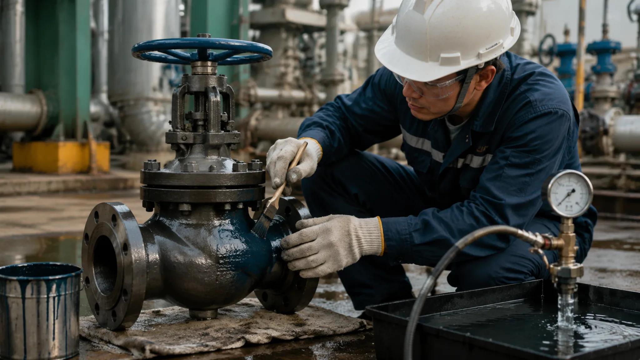
The manufacturer conducts a fire test on API 6D ball valves according to API 607, pressurizing the valve to 75% of the rated pressure, burning it in a 750–1000°C flame for 30 minutes, during which the leakage is continuously monitored not to exceed the specified value, and after cooling, seal and operating torque tests are performed to verify the fire resistance and structural integrity of the valve seat and packing.
manufacturer testing
System Construction & Pre-pressure
API 6D ball valve fire resistance test stands are usually built using 38mm wall thickness seamless steel pipes. The length of the upstream pipeline must reach more than 6 times the valve diameter to eliminate turbulence before the fluid enters the valve body, ensuring that the static pressure value presents a smooth straight line on the transmitter recorder. Technicians use 8 sets of bolts to connect the test ball valve with the flange, and the torque is executed with reference to the ASME B18.2.1 standard to prevent insufficient bolt pre-tightening force during thermal expansion, which leads to premature failure of the sealing surface.
After the pipeline structure is fixed, the layout of precision monitoring instruments determines the credibility of the data:
- K-type thermocouple: diameter 1.5mm, installed at a position 25.4mm away from the valve body surface.
- Temperature measurement block: material is 1020 carbon steel, size processed to 38mm square, with a hole drilled in the center to embed the probe.
- Level gauge: accuracy reaches 0.1ml, installed at the end of the downstream condensation pipe to collect trace internal leakage in real time.
- Pressure transmitter: range covers 0 to 42MPa, sampling frequency set to 10 times per second.
- Fire barrier: uses fire-resistant board with a thickness of 12.7mm to protect the actuator and non-test parts from high-temperature radiation.
Deionized water is selected for the test, and the water temperature is controlled between 5 degrees Celsius to 50 degrees Celsius. An air-driven booster pump pushes the water pressure to the 1.5MPa static pressure required for Class 150 valves, while for Class 300 A105 material valves, the starting pressure must be maintained at 3.8MPa. The system piping reserves about a 5% air pocket as a buffer to prevent pipeline vibration caused by the water hammer effect during violent temperature rise.
Two sets of temperature measurement blocks are distributed on the side of the valve body, respectively monitoring the absorbed heat of the middle cavity and the valve cover. The bottom gas pipeline grid is distributed with more than 24 high-performance nozzles, and the mixing ratio of gas and air is controlled at 1:10 by a proportional valve. The propane supply pressure is adjusted to 0.2MPa, which allows the flame to pull the local ambient temperature up to above 700 degrees Celsius within 120 seconds after ignition.
The heat application process requires a rigorous laboratory environment as support:
- Ambient wind speed: The laboratory remains closed, and the anemometer reading must be lower than 2m/s.
- Flame distance: The vertical distance between the nozzle outlet and the bottom of the valve is locked at 150mm.
- Downstream volume: The condensation tank volume is not less than 50L, with one-third of crushed ice pre-installed inside.
- Sealing grease: The valve seat must be thoroughly cleaned with solvent before the test, and it is strictly forbidden to remain any grease that has an auxiliary sealing effect.
- Installation posture: The valve stem must be installed horizontally to simulate the influence of lateral gravity on the ball valve seal pair in actual working conditions.
During the 5-minute observation period, the fluctuation of the pressure transmitter must not exceed 0.05MPa. Technical personnel fine-tune the pressure pointer to the 75% scale mark of the rated value through a manual pump. At this time, the valve is in a fully closed state, the downstream discharge valve is opened, and after confirming that there is no initial internal leakage, the data acquisition system starts the automatic recording mode.
The ball is pushed toward the outlet side valve seat under the thrust of 3.8MPa, and the PTFE sealing ring produces a compression deformation of about 0.2mm. This microscopic displacement simulates the stress state of the valve in the early stage of a fire; once the flame contacts the valve body, these polymer parts will undergo a transformation from solid to viscous state and then to carbonization.
The condenser adopts a spiral copper tube structure, immersed in a circulating cooling water tank, which can quickly cool steam above 200 degrees Celsius to below 30 degrees Celsius. This temperature difference treatment ensures that every drop of water flowing into the measuring cup is a manifestation of the real internal leakage amount, excluding the interference of gas expansion on volume measurement.
Measurement accuracy is guaranteed by the underlying electrical and mechanical parameters:
- Medium resistivity: must be greater than 1 megohm·cm.
- Bolt elongation: use an ultrasonic length measuring instrument to record the initial value, with an accuracy of 0.001mm.
- Variable frequency pump speed: locked at 1450rpm to provide stable back pressure.
- Shielded cable: adopts Teflon braided mesh to prevent ignition pulses from interfering with sensor signals.
A high-voltage discharge spark ignites all nozzles within 0.5 seconds, and the screen temperature curve begins to rise at a slope of 50 degrees Celsius per minute. At this time, the water inside the valve body expands due to heat, and the system overflow valve automatically opens, discharging excess pressure to the return tank, so that the valve cavity pressure is always locked within the range of plus or minus 0.1MPa of the set value.
The millivolt signal of the thermocouple and the gram change of the weighing sensor are transmitted to the server through optical fiber. Under this high-frequency monitoring, any minor design defects will be exposed. For example, if the thickness of the seat lip is less than 0.5mm, it will lead to premature deformation of the metal seal pair, resulting in exceeding the internal leakage standard within the first 10 minutes of the test.
760°C – 980°C High Temperature Burning
The control room presses the ignition switch, and the high-voltage discharge needle ignites 24 propane nozzles arranged in a surrounding manner within 0.5 seconds. Blue flames instantly wrap the entire valve body, and the pressure gauge pointer generates slight jumps due to thermal expansion. Propane supply pressure is maintained at 0.2MPa, ensuring the flame pushes the local ambient temperature to 700 degrees Celsius within 120 seconds.
15 minutes is the watershed of the test, at which time the temperature of the 1020 carbon steel monitoring block installed on the side of the valve body must break through 650 degrees Celsius. If the value displayed by the thermocouple is lower than this level, it indicates that the flame heat density is insufficient, and the test will be judged as invalid. Technicians control the flame environment temperature within the fluctuation range of 760 degrees Celsius to 980 degrees Celsius by adjusting the air mixing proportional valve.
The polytetrafluoroethylene (PTFE) sealing ring inside the valve body begins to lose physical strength at around 327 degrees Celsius. As the temperature climbs to 400 degrees Celsius, these polymer materials will undergo degradation and liquefaction, their volume shrinking rapidly and flowing away from the valve seat groove.
Pushed by the pressure, the ball produces a micro-displacement of about 0.5mm to 1.2mm toward the outlet side within the valve cavity. This displacement is not out of control, but to allow the ball sealing surface to eventually strike the pre-designed metal valve seat lip.
- Flame envelope height: covering 100mm above the valve centerline, ensuring the stuffing box is completely immersed in the sea of fire.
- Thermal gradient monitoring: when the outer wall temperature reaches 900 degrees Celsius, the fluid temperature in the center of the valve cavity usually rises to 210 degrees Celsius.
- Gas consumption: for a 10-inch Class 300 valve, it consumes about 18 cubic meters of propane per hour.
- Steam pressure: saturated steam is generated in the valve cavity, and the system overflow valve needs to open frequently at 1.1 times the set pressure.
| Monitoring Time Point | Core Monitoring Parameters | Allowable Deviation/Standard Value |
|---|---|---|
| 2nd Minute | Flame ambient temperature | Reach 700 degrees Celsius |
| 15th Minute | Monitoring block (Cube) temperature | Not lower than 650 degrees Celsius |
| 30th Minute | Average flame temperature | 760 to 980 degrees Celsius |
| Whole Process | Upstream test pressure | 75% of rated pressure (+/-10%) |
The flexible graphite packing located at the valve stem part withstands the most severe test, although its sealing performance at room temperature is weaker than the O-ring. Under high-temperature direct spray of 980 degrees Celsius, the graphite packing is kept tight by the 150Nm torque applied by the gland bolts. API 607 requires that the external leakage per minute must not exceed 100ml multiplied by the valve diameter in inches, which puts high requirements on the processing accuracy of the stuffing box.
The spiral wound gasket at the middle flange is also undergoing thermal cycling, and its internal 316 stainless steel belt and graphite belt produce non-uniform expansion at high temperatures. The 4.5mm thick gasket must maintain sufficient dynamic resilience during the fire burning process. If the bolts produce creep elongation at high temperatures, gasket pressure relief will lead to jet-like flames in the fire field, and the experiment will be immediately terminated due to safety risks.
The downstream condensation system is now operating at full load, with the spiral copper tube immersed in 0-degree Celsius crushed ice water. Steam squeezed out from the damaged valve seat gaps passes through the condensation tube and transforms into liquid water at a rate of several drops per second. The weighing sensor samples at a frequency of 10 times per second, transmitting data to the background server, automatically converting it into milliliters corresponding to each inch of diameter.
- Leakage condensation: the temperature of the liquid entering the measuring cup must be kept below 30 degrees Celsius to prevent evaporation loss.
- Sampling frequency: the data acquisition card sampling cycle is set to 100ms, capturing instantaneous pressure fluctuations.
- Pressure tolerance: during the test, the upstream pressure gauge displays 3.8MPa, with the fluctuation range locked at plus or minus 0.1MPa.
- Ambient wind speed: the laboratory forced exhaust system is adjusted to a weak mode, and the anemometer reading is locked at 1.5m/s.
Burning progresses to 25 minutes, and the valve body surface often appears dark red. At this time, the internal metal seal pair may have tiny physical gaps due to differences in thermal expansion and contraction coefficients. Engineers stare at the internal leakage curve on the monitoring screen; as long as the curve slope does not show a sharp increase, the fit between the ball and the metal valve seat is still tight.
Cooling & Function Review
The 1800-second fire resistance burning timing ends, the main gas valve is instantly cut off, and the roaring sound in the laboratory stops abruptly. At this time, the valve body surface is covered with a layer of grey-black scales falling off due to high-temperature oxidation, and the internal residual heat is still at a very high level. Technicians quickly start the remote water spray pump, and high-pressure nozzles target the valve body for uniform cooling at a flow rate of 20 liters per minute, aiming to pull the temperature of the monitoring block down to below 100 degrees Celsius within 600 seconds.
- Cooling flow: not less than 15 liters of constant temperature water per minute.
- Monitoring temperature drop: the monitoring block needs to drop from 980 degrees Celsius to 66 degrees Celsius within 10 minutes.
- Ambient temperature difference: the laboratory environment is maintained at 25 degrees Celsius to prevent violent airflow fluctuations from interfering with the cooling rate.
- Constant pressure: during the cooling stage, the upstream pressure is always locked at 3.8MPa, and fluctuations are strictly forbidden to exceed 0.1MPa.
Because the thermal contraction rate difference between the stainless steel ball and the carbon steel valve body reaches about 1.5 millimeters per meter, micron-level physical gaps will be generated between the metal seal pairs during the cooling process. If the valve seat pre-tightening design has defects, the internal leakage will suddenly surge during this stage, and the level gauge reading in the condensed water collector will jump at a speed of 5 milliliters per second.
Under the huge stress induced by sudden cooling, since the sealing material has already carbonized, the valve seat relies entirely on the elastic deformation of the metal lip to compensate for the contraction gap. Any processing error lower than 0.02 millimeters will lead to a complete collapse of the seal in the 100-degree Celsius temperature drop interval.
After cooling is complete, it enters a 5-minute static leakage test link. Technicians stare at the precision measuring cup with a volume of 500 milliliters, collecting every drop of water discharged from the condensation system. The API 607 standard has extremely low tolerance for this stage; for a 6-inch Class 300 ball valve, if its total leakage per minute exceeds 2400 milliliters, it is judged as a design failure, and the valve has insufficient residual pressure maintenance capability after fire extinguishing.
The pressure curve generated in real-time by the data recorder must present a nearly horizontal straight line. At this time, the upstream pressure sensor reading is 3.82MPa, and the downstream back pressure sensor displays 0.01MPa. This pressure difference simulates the residual stress state of the pipeline after a fire. Technicians begin to record the total drainage volume within these 300 seconds and convert it into the leakage constant under the standard diameter.
- Static monitoring duration: continuous recording for 300 seconds.
- Upper limit of allowable leakage: 400ml divided by inch diameter and then divided by minute.
- Medium temperature requirement: the liquid in the measuring cup must be cooled to below 30 degrees Celsius through the condenser.
- External observation: check if there is visible steam or liquid droplet ejection at the valve stem packing.
After determining that the static leakage meets the standard, the most critical action test immediately unfolds. Technicians rotate the manual operating mechanism or attempt to rotate the valve in the closed state to the fully open position through a remote drive device. At this time, the graphite packing inside the valve is tightly combined with the carbonized residue, and the operating torque will usually soar from 300Nm at room temperature to over 1200Nm, which requires the valve stem material to have extremely high torsional strength.
The opening process is not simple mechanical movement; it is verifying whether the ball has undergone fusion welding or jamming with the valve seat at high temperatures. If the sphericity deformation of the ball exceeds 0.05 millimeters, or the valve stem produces bending at high temperatures, then 1500Nm of torque cannot move the valve at all.
After the valve achieves full opening, it needs to maintain this state for another observation. Technicians measure the external leakage at the valve stem again to prevent new gaps generated by the displacement of the damaged graphite packing during the action process. At this time, the air pocket in the valve cavity will release part of the pressure, and the system overflow valve acts again to stabilize the pipeline pressure on the baseline of 3.8MPa.
- Operating torque record: use a digital torque wrench to record the peak value, with an accuracy of 1Nm.
- Opening time window: must be completed within 30 minutes after cooling to ambient temperature.
- Action integrity: must achieve a complete stroke from 0 degrees to 90 degrees, without halfway sticking.
- Secondary closing pressure: turn back to the fully closed position after opening, and re-establish the upstream seal.
After measuring at the fully open position, the valve is closed again for the final pressure relief performance evaluation. Technicians manually relieve the upstream pressure and observe the time required for the pressure gauge pointer to drop from 3.8MPa to 0MPa. If the pointer falls back too slowly, it indicates that the internal flow channel is blocked by carbonized soft seal residue; although the seal passed the test, as a flow component, the valve will still be judged as not meeting the functional requirements of API 6D.
The data density of the entire cooling and review process is extremely high, and the transmitter collects 10 sets of signals per second. Engineers from third-party certification bodies such as TUV will personally check the torque curve and leakage weight records; any gap in data could lead to the invalidation of the entire experiment costing tens of thousands of yuan.
- pressure relief record: relief from 3.8MPa to atmospheric pressure must be completed within 10 seconds.
- Weighing sensor range: 0 to 5000 grams, resolution 0.1 grams.
- Monitoring block final temperature difference: the deviation between the three monitoring points must not exceed 15 degrees Celsius.
- Seal surface inspection: the valve must be disassembled after the test to measure the plastic deformation of the metal valve seat lip.
Technical personnel remove all sensor cables and summarize the collected four-dimensional data of pressure, temperature, flow, and torque. The finally formed fire test report usually exceeds 30 pages, covering details from 25-degree Celsius initial pressure to 980-degree Celsius fire burning, and then to 1200Nm strong twisting after forced cooling. Only when all data points fall within the envelope defined by API 607 can this ball valve obtain a globally recognized fire resistance certificate.
quality assurance
Coverage
The seventh edition of API 607 clarifies the coverage ability (Coverage) of the sample valve to mass-produced products. This set of rules avoids repeated experiments for every specification. Manufacturers select boundary specifications such as NPS 2 or NPS 8 to obtain a wider supply qualification.
Sample selection determines what kind of orders the factory can take. The table below shows the coverage ratio of commonly used diameters, and this multiple relationship is a regulation that must be consulted when selecting samples in the laboratory:
| Test Sample Diameter (NPS) | Coverable Mass Production Diameter Range (NPS) |
|---|---|
| 1/4, 1/2, 3/4 | 1/4, 3/8, 1/2, 3/4, 1 |
| 2 (DN50) | 2, 2.5, 3, 4 |
| 6 (DN150) | 6, 8, 10 |
| 8 (DN200) | All diameters of 8 and above |
Selecting NPS 2 as the test object, after passing the test, products of the same diameter can be manufactured, compatible with 1.5 inches or upward compatible with 4 inches. If the factory undertakes a 24-inch large-diameter pipeline project, a sample valve of no less than 8 inches must be put into the fire field.
Pressure rating qualification follows the principle of high pressure covering low pressure. The table below lists the corresponding qualifications for different pressure ratings:
| Test Sample Pressure Rating (Class) | Coverable Mass Production Rating Range (Class) |
|---|---|
| 150 | 150 |
| 300 | 150, 300 |
| 600 | 150, 300, 400, 600 |
| 1500 | 900, 1500 |
A Class 300 sample valve withstands high pressure in the fire for 30 minutes, and the certificate is used for Class 150 products. During the Class 600 sample test, the internal static pressure is about 7.5 MPa, which is stricter than the 2.0 MPa for Class 150.
The choice of materials is limited. API 607 divides valve body materials into carbon steel, alloy steel, and stainless steel. When an ASTM A105 carbon steel valve completes the test, the certificate cannot be used for F316 stainless steel valves.
Carbon steel has a different deformation amount from stainless steel at 800°C. Stainless steel sample testing qualification usually can cover other austenitic alloy materials. The internal soft seal PTFE of the ball valve melts at 327°C.
The fire field environment temperature is stable at 760°C to 980°C. The soft seal melts and is destroyed within the first 10 minutes before the fire. QA verifies the hard contact effect of the backup metal valve seat and the ball.
The surface roughness of the ball must reach below Ra 0.4 um. API 607 allows a 2-inch valve to have an internal leakage not exceeding 30 ml within 30 minutes. The external leakage limit is 100 ml per inch diameter per minute.
The machining tolerance of the seal pair is controlled within 0.01 mm. Full bore valve samples can cover reduced bore valves. The ball of a full bore is larger, and the pressure generated by thermal expansion is stronger.
A reduced bore valve has a small ball and less heating surface, so it cannot represent full bore performance. The density of the graphite packing at the valve stem should be between 1.3 to 1.6 g/cm3. Low density will lead to external leakage spray.
High density will make the valve unable to rotate after thermal expansion. After cooling, the sample valve should undergo full open and full close operations to check for jamming. The fire-safe lip angle on the drawing is designed to be 15 to 30 degrees.
The metal valve seat rebound stroke data must match the mass production records. Patrol inspection uses calipers to measure the depth of the fire-safe groove, and the error must not exceed 0.1 mm. Certificates are issued by institutions such as TUV or DNV.
Inspectors check sample drawings and put a steel stamp on the valve body. After the test, the valve is disassembled to check the ball deformation. The thickness of the tungsten carbide coating should be between 0.15 mm to 0.25 mm.
Manufacturers check mass production lists every year. If a Class 300 certificate is used in a Class 600 project, the certificate is void. Design parameters and material grades must be consistent with the test sample valve.
The test equipment is configured with 38 mm square temperature measurement cubes. Sensors are installed at a position 12.5 mm away from the valve body. The data acquisition system records temperature, pressure, and leakage every 2 minutes.
The cooling stage uses air or water. The sample valve can only undergo subsequent sealing tests after the temperature drops below 100°C. The low-pressure test pressure is set at 0.2 MPa, and the holding time is no less than 5 minutes.
The compression of the graphite gasket is controlled at 25% to 30% of the initial thickness. This amount of deformation can offset the warping of the metal flange at high temperatures. All pressure gauge accuracy must reach 0.1%.
The API 607 coverage range is the red line for manufacturer supply. Sales behavior beyond the range is a violation. The QA department conducts monthly random checks on the dimensions of fire-safe seals on the assembly line to ensure consistency with the sample valve.
High-frequency dimensional detection and hardness detection ensure mass production quality. The hardness difference between the ball and the valve seat is maintained at HRC 3 to 5. This configuration prevents seizure caused by dry metal friction.
Fire Test
API 607 fire test requires the sample valve to be fully exposed to the flame envelope. The nozzle layout on the test stand determines the heat distribution, and the flame must completely cover all connections of the valve body and valve cover.
The recorder is connected to 38 mm metal temperature measurement blocks. These cubes are distributed around the valve, each block has a hole drilled in the center for a thermocouple, and the installation position is kept at 12.5 mm from the valve body surface.
The data acquisition system records parameters every 120 seconds. The flame temperature must be stable between 760°C and 980°C within 30 minutes. If the average reading is lower than 760°C, the experimental data will be directly invalidated.
During the test, the internal static pressure of the valve is set at 75% of the maximum working pressure. For Class 150 valves, the pressure gauge value is about 1.5 MPa, while for Class 300 samples, it must be maintained at 3.75 MPa.
- Burning time lasts for a full 30 minutes.
- Temperature measurement blocks must reach 650°C within 15 minutes.
- Pressure fluctuation range is limited to within plus or minus 10% of the set value.
- The test medium uses room temperature water, provided by a water storage tank pressurized by nitrogen.
- The downstream of the valve seat is connected to a measuring cylinder with a condensation function for measuring internal leakage.
- Observe and record whether there are jet flames exceeding 100 mm at the graphite packing of the valve stem.
The polytetrafluoroethylene soft seal inside the ball valve begins to soften and decompose at 327°C. At this time, water flow will pour toward the outlet end through the burned gaps. Testers need to collect this condensed water in real-time through graduated cylinders.
For an NPS 2 diameter sample, the upper limit of total internal leakage during the 30-minute burning period is 30 ml. Exceeding this value indicates a defect in the physical fit of the metal fire-safe lip.
The control of external leakage is even more stringent. The leakage of each inch of diameter is limited to within 100 ml per minute. This depends on the compression of the valve stem graphite packing, and its packing density needs to be between 1.3 to 1.6 g/cm3.
After the 30-minute burning stage, close the gas supply valve. The sample enters the natural cooling or forced cooling process. It must wait until the temperature of the valve body shell drops below 100°C before starting subsequent links.
The first test after cooling is the 0.2 MPa low-pressure seal experiment. At this time, there is no high pressure to push the ball, and it relies entirely on the Inconel X-750 spring behind the metal valve seat to provide an initial thrust of 500 to 1000 Newtons.
The low-pressure holding must last for 5 minutes. If the internal leakage increases at this time, it is usually because the metal seal ring has undergone plastic deformation exceeding 0.1 mm at high temperatures.
- The overall temperature of the sample must drop below 100°C before testing.
- 0.2 MPa hydrostatic test duration is 5 minutes.
- Opening torque test, full open and full close once under high pressure.
- Check the residual pre-tightening force of the valve body connection bolts after 800°C.
- The operating torque of the valve stem must not exceed 3 times the design limit.
- The sphericity deviation of the secondary sealing surface is controlled within 0.05 mm.
The strength of B7 bolts at 800°C is only 10% of that at room temperature. If the design is unreasonable, the valve will jam during the cooling process due to material stress release.
The manual actuator must be able to force open the valve. The QA team will record the torque curve at the moment of opening. Usually, the opening torque of a Class 600 valve will surge from the usual 200 Nm to over 600 Nm.
The final stage requires a disassembly inspection of the sample. Engineers will focus on observing the hard alloy coating on the ball surface. Tungsten carbide spray thickness should be maintained at 0.15 to 0.25 mm to prevent scratches during metal-to-metal friction.
The coating hardness needs to reach above HRC 70. If cracks or peeling are found in the coating after disassembly, it indicates that the thermal stress control in the spraying process is not up to standard and cannot maintain seal integrity in a fire.
The graphite gasket should maintain a certain compression margin during disassembly. Usually, the compression amount should be controlled at 25% to 30% of the initial thickness. This deformation can compensate for the slight warping of metal flanges at 900°C high temperature.
All recording papers, pressure curve charts, and steel stamp information from third-party witnesses must be archived for 10 years. The accuracy error of laboratory flow meters must not exceed 0.1%.
Grinding marks on the sealing surface should appear as concentric circles under a microscope. A surface roughness of Ra 0.4 um ensures the filling ability of the metal lip on a microscopic scale.
Fire-safe Seal Structure
At the beginning of a fire, soft seals such as polytetrafluoroethylene (PTFE) or para-polyphenylene (PPL) undergo melting loss or carbonization at around 327 degrees Celsius to 400 degrees Celsius.
The valve seat support displaces toward the ball under the thrust of the internal Inconel X-750 spring. This spring has undergone aging treatment at 730 degrees Celsius for 16 hours to ensure it can still output an initial thrust of 500 to 1000 Newtons in a 980-degree Celsius fire field.
At this time, the fire-safe lip (Fire-safe Lip) on the valve seat directly contacts the ball surface. The physical width of this lip is usually designed between 1.5 mm to 3.0 mm; too narrow will lead to excessive contact stress and plastic deformation, while too wide will fail to form an effective sealing specific pressure at low pressure.
- The contact angle between the fire-safe lip and the ball is usually set between 15 degrees to 30 degrees.
- The machining roughness of the lip surface is strictly controlled at Ra 0.4 micrometers.
- The roundness tolerance of the ball must be better than 0.01 millimeters to ensure concentricity during rotation.
- Metal valve seat material commonly uses SS316 with Stellite No. 6 hard alloy surfacing on the surface.
- The hard alloy layer thickness is maintained at 1.5 millimeters to 2.0 millimeters.
- The hardness of the surfacing layer must reach above HRC 40 to resist erosion under high temperatures.
Supersonic flame spraying (HVOF) technology is used to spray tungsten carbide (WC), with a thickness controlled between 0.15 mm to 0.25 mm. The coating with a hardness exceeding HRC 70 can prevent the metal valve seat from scratching the ball under dry friction.
If the coating thickness is lower than 0.1 mm, high-temperature airflow will quickly strip the hard layer during the 30-minute burning experiment. The API 607 standard allows for very small internal leakage; for an NPS 6 diameter valve, the leakage per minute cannot exceed 90 ml, which depends entirely on the integrity of the coating.
The seal at the valve stem is undertaken by flexible graphite packing rings. The carbon content of this material must be greater than 98%, and it will not instantly gasify like rubber O-rings in a 1000-degree Celsius flame. The density of the packing set is controlled at 1.4 g/cubic centimeter, ensuring it can fill valve stem tolerances after thermal expansion.
- The design gap of the valve stem fire-safe step is kept at 0.1 mm to 0.2 mm.
- The loss on ignition of graphite packing must be less than 1% at 600 degrees Celsius.
- The spiral wound gasket with graphite filler at the middle flange has a total thickness usually of 4.5 mm.
- The internal strengthening ring of the gasket uses SS316L material, with a thickness of about 3.0 mm.
- The pre-tightening force of bolt connection needs to reach more than 50% of the material yield strength.
- Prevent the flange from thermal warping at 850 degrees Celsius, which leads to external leakage.
Through 304 stainless steel springs and pins, it ensures the resistance value between the ball, valve stem, and valve body is lower than 10 ohms. At the fire scene, this discharge path can prevent accumulated static electricity from igniting leaked oil and gas media.
The O-ring at the back of the valve seat will disappear after the fire starts, and QA regulations require that a metal inclined plane must be machined at this position. Driven by the medium pressure, the entire valve seat assembly will be pressed against the ball like a piston. For a Class 600 valve, this self-sealing pressure can reach 10 MPa.
The requirement for depth tolerance of the fire-safe groove in the manufacturing process is plus or minus 0.05 mm. Once the machining exceeds the tolerance, the metal lip may fail to fit the ball vertically after the soft seal is burned out, leading to test failure. Obtaining an API 607 certificate requires every physical dimension to be verified by a three-coordinate measuring machine.
- Low-pressure seal test pressure is maintained at 0.2 MPa.
- High-pressure seal test pressure is set at 1.1 times the rated working pressure.
- The hardness of the gland bolts should be controlled below HB 235 to prevent stress corrosion cracking.
- The single compression of the seat rebound spring must not exceed 20% of its free height.
- Cast valve bodies must pass radiographic testing (RT) to ensure no shrinkage holes inside.
- Forged valve bodies need to undergo ultrasonic testing (UT) to detect cracks larger than 2 mm.
During the grinding process of metal sealing surfaces, 400 mesh to 1000 mesh grinding paste is used. This fineness ensures that the contact surface between metal and metal can achieve bubble-level sealing without soft seal assistance. In laboratory simulations, this structure can withstand more than 30 minutes of 900-degree Celsius high temperature baptism.
fire-safe validation
Environment & Thermal Parameters
The nozzle layout of the test stand must form an enveloping flame, ensuring the flame covers the valve body, middle flange, and valve stem area of the API 6D ball valve 360 degrees. Propane gas supply pressure is usually stable at 0.15 MPa to 0.25 MPa to maintain continuous energy output at the nozzles, ensuring the thermal output power reaches above 1.0 MBtu per hour.
Temperature measurement blocks installed under the valve adopt 38mm by 38mm by 38mm carbon steel cubes. These temperature measurement blocks simulate the heating rate of the valve body metal through the thermal inertia of their own mass. Within 15 minutes after the start of the test, the temperature measurement block must climb from room temperature to 650°C, otherwise the experimental data will be considered invalid.
- The center point of the temperature measurement block is kept 25mm away from the valve body surface.
- The flame thermocouple near the valve stem packing needs to monitor fluctuations from 760°C to 980°C.
- The inlet water temperature of the downstream condenser needs to be suppressed below 40°C to prevent medium vaporization.
- The upstream water tank is pressurized through nitrogen cylinders to maintain the test pressure deviation within plus or minus 5%.
- The valve axis must remain horizontal, simulating the most common layout of pipelines in the field.
- The wall thickness of the measurement pipeline must not be less than 1.5mm to prevent bursting halfway through combustion.
The thermocouple collects temperature rise data every 30 seconds, recording the expansion changes after the valve body outer wall is heated in real-time. For A105 carbon steel, the thermal expansion coefficient is about 0.000012. Under an 800°C temperature difference, a 10-inch valve body will produce about 3.5mm of thermal displacement in the length direction, and this mechanical stress will directly stretch the middle flange bolts.
When the flame temperature breaks through 327°C, the PTFE soft seals in the valve seat begin to undergo plastic fluidization, and then completely carbonize around 400°C. At this time, the ball is pushed by the medium pressure difference of 5.0 MPa (taking Class 300 as an example) from upstream, moving 0.5mm to 1.5mm toward the downstream side, and a hard collision occurs with the fire-safe metal lip on the valve seat.
- The sealing surface width of the metal seat ring is designed between 1.5mm and 3.0mm.
- The roundness error of the fire-safe lip must be better than 0.015mm.
- The pre-tightening force of the graphite packing at the valve stem must reach above 35 MPa.
- The middle flange uses a spiral wound gasket of 316L material plus flexible graphite.
- The support spring must select Inconel X-750 material.
- The valve body wall thickness needs to meet the minimum safety margin specified by API 6D.
After the burning stage lasts for 30 minutes, the operator needs to turn on the spray device to perform forced cooling. Cold water injection will cause the valve body surface temperature to drop sharply from 800°C to below 100°C within 5 minutes. This violent temperature change tests the elastic modulus maintenance ability of the support spring behind the valve seat, preventing the metal seal pair from disengaging due to cold contraction.
During cooling, the condensed water volume collected by the downstream measuring cylinder records the internal leakage data of the valve seat. According to API 607 regulations, for a DN100 (4-inch) ball valve, the upper limit of total internal leakage during combustion and cooling is 1600 ml per minute. If the actual measured value reaches 1800 ml, even if the valve body exterior is intact, the test will fail.
The valve is horizontally installed on the stand, with the downstream pipeline end connected to a condensation coil. The condensation tube must be completely immersed in an ice-water mixture to ensure that every drop of high-temperature water vapor discharged can be liquefied and counted into the measuring cylinder, and the measurement error must be controlled at the 1 ml level to ensure the precision of leakage statistics.
- The test pressure of Class 150 valves is set at 1.4 MPa.
- The allowable external leakage upper limit for a 2-inch valve is 200 ml.
- Cooling water flow needs to be maintained at 10 L/min to 15 L/min.
- The steam leaking from the valve stem is introduced into the condenser through an aluminum foil cover.
- The sampling frequency of the recorder is not lower than 5 times per second.
- All recorded data must be accurate to two decimal places.
The value displayed by the torque wrench is often 3 to 5 times that of normal times. This is because internal parts have generated mechanical interference due to thermal expansion and contraction, or soft seal residues have adhered to the ball surface. The operator needs to force open the valve through a 1.5m long extension bar.
If the ball produces mechanical adhesion with the valve seat during rotation, the torque will instantly soar to above 500 Nm. This tests the shear strength of the valve stem; the valve stem material is usually selected as 17-4PH stainless steel and heat-treated to ensure that it still has sufficient mechanical properties after being heated, so as not to break during the twisting operation.
- Class 300 valves need to undergo post-fire static pressure at 5.2 MPa.
- The expansion coefficient of 304 stainless steel at 800°C is about 0.000018.
- The chloride ion content of the test medium water must be lower than 25 ppm.
- The vent valve must completely exhaust the air in the valve cavity before firing.
- The pre-tightening force of the packing gland bolts must be accurate to 25 Nm.
- All pressure gauges must be within the valid verification cycle.
The connecting pipes at both ends of the valve must have sufficient rigidity to prevent self-weight sagging at 1000°C high temperature. Pipe wall thickness needs to match the test valve to avoid the inability of thermocouple readings to reflect the real heating of the valve body due to thermal capacity differences. All pipe joints must use metal seals to eliminate additional interference during the test.
The internal leakage rate during the burning period cannot exceed 400 ml per inch of nominal diameter per minute. For a 6-inch ball valve, the total internal leakage within half an hour must be suppressed within 72 L. The valve stem stuffing box, as a high-incidence area for external leakage, needs to use flexible graphite rings with a purity of over 99.5% to prevent oxidative ablation under high temperatures.
At the middle flange, a spiral wound gasket with graphite filler is used. The resilience of the gasket in a fire is the line of defense to prevent medium ejection, and its compression rate must be maintained between 25% to 35% to compensate for the creep elongation of bolts at high temperatures. If B7 material is selected for bolts, its tensile strength will decay rapidly at high temperatures, and it needs to be countered by increasing the pre-tightening force.
- The minimum division value of the flow meter needs to reach 0.1 L.
- Ambient wind speed must be controlled below 2 m/s.
- The layout interval of propane burners is 100mm.
- Water temperature during the cooling stage must not exceed 25°C.
- Check the hardness of the valve sealing surface before each test.
- Disassembly of the valve seat after the test needs to retain photographs of seal marks.
The witness engineer from the third-party institution will compare the ball roundness before and after the test. If the ball shows an ellipticity deformation exceeding 0.05mm after fire burning, the metal sealing performance will be greatly reduced. The experimental conclusion depends on those 30 minutes of fierce fire, as well as the opening and closing cycle after the fire is extinguished. If the valve stem bends more than 2 degrees, the driving device may fail to operate due to jamming.
Pressure & Leakage
In the API 607 fire test, pressure compensation and precision measurement of leakage are the only yardsticks to judge whether a ball valve can survive a fire. Before the experiment starts, the interior of the valve will be filled with fresh water medium at 75% of the rated working pressure, and pressure will be replenished in real-time through a high-pressure nitrogen cylinder group during the entire 30-minute incineration process.
If taking a Class 300, 100mm (4-inch) nominal diameter ball valve as an example, the test pressure must be constant between 5.1 MPa and 5.3 MPa. Even at the moment the PTFE valve seat burns out, the pulse fluctuation captured by the pressure transmitter must not exceed 5% of the set value, otherwise, the action of the system vent valve will interfere with leakage collection.
- The capacity of the internal leakage collection container during the burning period is usually set at 100 L.
- The pulse equivalent of the flow meter needs to be accurate to 0.01 L per pulse.
- A back pressure valve must be installed downstream of the valve seat to maintain a micro-positive pressure of about 0.02 MPa.
- The total length of the condensation pipeline is usually not less than 3000 mm.
- The chloride ion concentration in the medium water needs to be controlled within 25 ppm.
- The division value of the weighing sensor needs to reach the 1 gram level.
During 30 minutes of continuous fierce fire, the medium blocked by the metal auxiliary seal of the valve must reach more than 95%. If the condensed liquid in the collection bucket exceeds 32 L at the 20th minute, the tester will immediately cut off the gas source and declare the verification failure, because this predicts that medium leakage at the fire scene will lead to fire out of control.
| Monitoring Indicator | Specification Reference (4 Inch) | API 607 Standard Limit | Field Acquisition Accuracy |
|---|---|---|---|
| Internal leakage during burning (Through-seat) | DN100 | 1600 ml/min | ±1 ml |
| External leakage during burning (External) | Stem/Flange | 400 ml/min | ±0.5 ml |
| Total internal leakage during cooling | 5-minute cooling period | 1600 ml/min | Real-time weighing |
| Total external leakage during cooling | 5-minute cooling period | 400 ml/min | Visual capture |
External leakage monitoring areas are concentrated at the valve stem stuffing box and middle flange connection. At 900°C high temperature, graphite packing will undergo trace volume compensation; if a jet-like leakage exceeding 400 ml per minute occurs here, the flame will burn upward along the valve stem and destroy the drive actuator.
Testers need to arrange aluminum foil diversion covers around the middle flange to guide the leaked steam to the cooling coil. At this time, if the ambient wind speed is higher than 2 m/s, it will take away heat and dilute the leakage concentration, so the set height of the wind barrier must exceed the top of the valve by 500 mm.
After entering the cooling stage, the pressure data acquisition frequency rises to 10 times per second. With cold water spraying, the valve body temperature drops sharply from 800°C, and the contraction of metal parts will cause instantaneous fluctuations in seal specific pressure. For Class 150 valves, the pressure needs to be maintained at 1.4 MPa at this time, observing the secondary total leakage within 5 minutes of cooling.
- The residual elasticity of the valve seat spring after high temperature must be maintained at more than 60% of the initial value.
- The surface hardness of the 316L stainless steel ball must not decrease by more than 15% after fire burning.
- The elongation of the gland bolts needs to be monitored in real-time through dial gauges.
- The cooling water nozzle should be kept 200 mm to 300 mm away from the valve surface.
- The cooling rate needs to be controlled at about 140°C per minute.
- The contact bandwidth of each pair of seals needs to be maintained at 1.2 mm to 2.5 mm.
If the valve performs stably during the cooling period, the subsequent pressure recovery test will push the internal pressure to 100% of the rated value again. For Class 600 rating, this value will be as high as 10.2 MPa. At this time, any minor metal scratch will form an erosion channel under ultra-high pressure.
In the final opening and closing operation, the valve needs to complete one full open and full close under maximum differential pressure. If the valve stem bending due to thermal stress exceeds 0.5 mm, the opening torque will break through 3000 Nm. For valves above DN200, a hydraulic pump station is usually needed to assist the drive, and the recorder will automatically record the pressure drop curve at the moment of opening.
Metal-to-Metal
API 6D ball valves can maintain seals in incineration tests, mainly depending on the metal fire-safe lip reserved on the valve seat support. When the laboratory flame heats the PTFE or PEEK seat ring to above 327 degrees Celsius, the soft seal material will undergo plastic fluidization and be squeezed out of the seal groove; at this time, the ball generates an axial displacement of 0.5mm to 1.5mm toward the downstream side under the physical thrust of the valve cavity pressure.
This displacement allows the ball surface to directly contact the fire-safe lip on the valve seat metal substrate. In the drawing design stage, the width of this metal lip is usually limited between 1.5mm to 3.0mm to ensure that enough unit area sealing specific pressure can be generated at the moment of contact, and its value often needs to reach above 150 MPa to forcibly block the medium flow channel.
- The thickness of the Stellite 6 hard alloy layer sprayed on the ball surface should be between 0.3mm to 0.5mm.
- The roundness tolerance of the metal seal pair under the machining center must be controlled within 0.01mm.
- The fire-safe lip angle mostly adopts a 30-degree or 45-degree bevel to increase the contact line length.
- The valve seat substrate material is usually selected as nickel-plated A105 or 316 stainless steel.
- The roughness Ra of the ball surface needs to reach 0.4 micrometers, reducing the friction coefficient between metals.
The processing accuracy of the fire-safe lip at the bottom of the valve seat support is the defense line of the entire valve; if the CNC machine tool produces a 0.02mm runout during turning, microscopic gaps will appear in the metal hard contact under high temperatures, leading to erosion-type internal leakage of medium under 5.0 MPa pressure.
The physical collision between the ball and the metal lip is not a simple superposition, but involves material thermal expansion compensation. Under 800 degrees Celsius flame, the linear expansion coefficient of 316 stainless steel is about 0.000018 per meter per degree; a ball with a diameter of 250mm will increase in diameter by about 3.6mm after being heated, which requires the seat seal groove to have sufficient radial redundancy space.
To prevent microscopic fusion welding between the ball and the metal valve seat under high temperatures, manufacturers will coat a layer of special dry powder lubricant or high-purity molybdenum disulfide on the spherical surface. This coating will not fail at 1000 degrees Celsius, ensuring that the friction torque of the ball rotation will not break through the output upper limit of the actuator when performing opening and closing tests in the late stage of a fire.
- Support springs behind the valve seat should select Inconel X-750 nickel-based alloy.
- The reduction ratio of elastic modulus of the spring at 500 degrees Celsius should be controlled within 15%.
- The pre-tightening force set value of the single-side valve seat is usually 1.2 times the rated working pressure.
- The width of the metal contact band increases with valve specifications; an 8-inch valve needs to reach 2.2mm.
- The hardness of the ball surface needs to reach HRC 38 to 42 to prevent being scratched by the metal lip.
In the laboratory, when the water pressure gauge pointer vibrates violently at the moment of soft seal destruction, it indicates that the ball is looking for a metal seal position. If the pointer cannot stabilize within 30 seconds, it indicates that the geometric shape of the fire-safe lip failed to achieve full fit under the action of pressure difference.
The secondary seal between the valve seat support and the valve body is equally important; a set of flexible graphite rings is usually pre-positioned here. After the soft seal O-ring fails, the graphite ring is squeezed to the bottom of the packing groove under an initial spring pressure of about 0.3 MPa, filling the gap generated by thermal expansion; its carbon content needs to be above 99% to prevent oxidation and embrittlement during continuous incineration.
At the middle flange connection, the graphite filler in the stainless steel spiral wound gasket undertakes the same duty. The tensile strength of bolts at 800 degrees Celsius will shrink to about 30% of that at room temperature; therefore, the pre-tightening torque of Class 600 rating valve bolts needs to be increased from 500 Nm to 750 Nm to reserve enough thermal creep margin and prevent external fire spray.
- The radial compression rate of the graphite ring needs to reach 25% to 30% during assembly.
- The inner strengthening ring thickness of the middle flange gasket is usually 3.0mm.
- The fit tolerance between the seat sleeve and the valve body hole should select H7/g6.
- The edge of the ball through-hole needs to be rounded to prevent scratching the metal sealing surface.
- All seal components must not show piece dropping or powdery disintegration after the fire.
Every set of metal seal pairs undergoes color inspection before leaving the factory, requiring red lead powder to be uniformly distributed on the 360-degree contact surface. This purely manual grinding process determines whether the valve is a barrier to block disasters or a leaking metal shell under extreme fire fields.
This metal-to-metal forced seal will face a secondary test during the cooling stage of the API 607 standard. The temperature difference stress caused by cold water spray will make the valve seat support generate a backward retraction force; if the residual stress of the support spring is insufficient to offset this thermal shock, the metal sealing surface will instantly disengage, generating a gushing internal leakage of more than 2000 ml per minute.
For double block and bleed (DBB) structure ball valves, the fire-safe lips of the two valve seats need to meet seal requirements simultaneously. The design of the relief hole must avoid the seal line to prevent high-temperature media from washing out the metal lip when the valve cavity pressure rises abnormally. Every milliliter of leakage captured by laboratory recorders is a quantitative audit of the matching between valve seat support rigidity and ball roundness.

")