
Ball valve before installation should check specification and pressure grade, perform appearance and sealing face inspection and use 0.5MPa air pressure pre-test no leakage, clean pipeline impurities; after installation according to 1.25 times working pressure perform water pressure test 10 minutes, allow trace leakage ≤ standard value, at the same time check opening/closing torque change controlled within ±8% inside, ensure operation stable.
pipeline cleaning
Impact of Pollutants
When ball valve from open turns to close when, gap between valve seat and ball from 5mm rapidly shrinks to 0mm, at this time flow velocity because Venturi effect steeply increases, carried 500 microns above hard particles will with 30m/s speed impact valve seat.
PTFE valve seat hardness is only R58 around, while carbon steel welding slag hardness generally exceeds HB200. Particles embedding into valve seat after will form permanent bulge, ball every time rotating all will on its surface carve out 0.05mm wide annular groove.
- This kind of wear leads to leakage amount from 0.01 cubic centimeters per minute sharply increase to 10 cubic centimeters above.
- Valve cavity bottom if accumulates exceeding 20mm thickness dust, will hinder valve seat spring compensation displacement.
- Containing 5% concentration silicon dioxide medium, its erosion rate than pure medium is higher by 8 times.
High flow velocity flushing not only is for removing floating dust, more needs to produce enough shear stress to peel off inner wall oxide film. Aiming at DN200 caliber pipeline, needs to guarantee per hour 170 cubic meters flow rate just can maintain 1.5m/s lowest flushing linear speed.
If flushing flow velocity lower than 0.7m/s, particle size 1mm, density 7.8g/cm3 metal debris will deposit at pipe bottom forming creeping flow. These impurities under valve throttling state will accumulate at sealing ring back part, make spring preload lose 30% above, causing middle/low pressure working condition under continuous leakage.
- 304 stainless steel pipeline to chloride ion extremely sensitive, flushing water temperature rises to 60 degrees Celsius when corrosion rate doubles.
- System cleaning pressure needs to reach working pressure 1.1 times.
- Branch pipe and main pipe connection place cleaning blind zone usually as long as 300mm, must separately add discharge port.
Gas under 0.7MPa pressure releasing when, outlet kinetic energy must reach normal operation state 1.2 times. Target plate should select 2mm thick aluminum plate, because its hardness is moderate, can accurately record particle impact pits.
Experiment records show, if target plate on exists diameter 0.5mm pit, explaining system inside still remains per meter 10g above loose impurities. These residues entering ball valve after, will make operating torque from rated 120N·m soar to 200N·m, inducing actuator overload.
- Instrument air pipe blowing needs to last 24 hours until dew point reaches minus 45 degrees Celsius.
- Steam system needs to experience 3 times above heating cooling cycles to utilize thermal expansion and contraction to peel off oxide scale.
- Every one 90 degree elbow all will produce 15% pressure loss, blowing point distance must not exceed 500 meters.
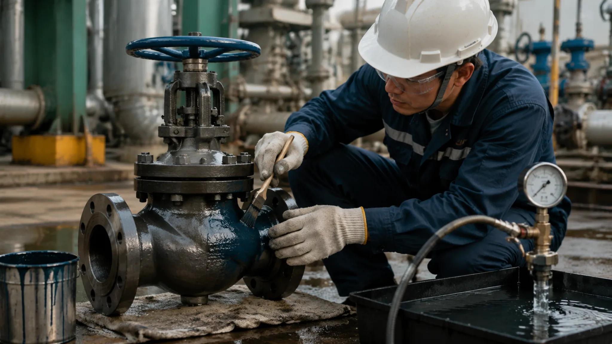
On-site installation ball valve before must measure flange face flatness, tolerance should be controlled within 0.15mm inside. If sealing face adheres 80 microns thickness paint residue, tightening bolts when produced non-uniform pressing force will lead to valve seat deformation 2 degrees.
This kind of tiny deformation under 6.4MPa high pressure will lead to valve seat support ring receive force non-uniform, fatigue life shorten 60%. Regarding hydrogen or high purity oxygen pipeline, any trace amount grease (testing standard is per square meter residual amount lower than 100mg) under high speed friction all possible induce chemical reaction, directly burn down sealing components.
Blowing
At cleaning one DN150 caliber pipeline when, instantaneous air flow rate needs to reach per hour 4000kg around, just can ensure kinetic energy enough to lift up pipe bottom precipitated metal debris. If air compressor rated displacement is only per minute 10 cubic meters, blowing distance should be controlled within 150 meters inside, otherwise midway pressure drop will lead to terminal flow velocity lower than 20m/s, impurities unable along with airflow discharged.
Pipeline material difference directly determines blowing target plate selection standard and judgment basis. Below table recorded different medium pipelines under 0.7MPa pressure specific acceptance indicators:
| Pipeline Material | Target Plate Material | Surface Hardness Requirement | Qualified Record Standard |
|---|---|---|---|
| Ordinary carbon steel pipe | Polished aluminum plate | HB 25-35 | 0.3mm pit point less than 1 piece/cm2 |
| Stainless steel pipe | Industrial pure copper plate | HB 80-100 | No naked eye visible obvious scratches |
| Alloy steel pipe | 1Cr13 steel | HB 150-180 | Continuous two times blowing no new impact point |
System needs first preheat to 250 degrees Celsius, subsequently in short time perform fast cooling, this temperature difference alternation will make inner wall thickness about 0.2mm triiron tetroxide layer produce cracks and fall off. One complete cycle usually consumes time 2 hours, if blowing temperature difference lower than 100 degrees Celsius, adhered firmly welding slag in future operation will continuously fall off, directly damage ball valve ball chrome plating layer.
Regarding 1000 meters around gas transmission trunk line, initial discharge port dust content often reaches per minute 5-10kg. Blowing continuing 4 hours after, exhaust gas inside solid concentration needs to drop to 0.1g per cubic meter below. At replacing formal target plate before, can at outlet add one 0.5mm aperture temporary filter screen perform pre-inspection, avoid frequent consumption high precision target plate.
One DN100 pipe port under 0.8MPa blowing pressure will produce about 1500N recoil force. If not installed 12.9 grade strength U-type bolt fixed on H-beam bracket, pipeline will produce 15mm above swing amplitude. This kind of vibration will upward transmit to already installed well small branch valve, leading to its root weld seam due to fatigue produce micro cracks.
Blowing gas must pass through oil-free drying treatment, oil content needs lower than 20mg per cubic meter. If blowing air inside contains condensed water, pipe inside dust will condense into paste-like substance. This will lead to ball valve operating torque from design value 80N·m soar to 140N·m, directly causing pneumatic actuator at performing 10% partial stroke test when occur stuck.
In 10 inches pipeline inside, close to pipe wall airflow velocity than center position lower about 30%. Taking blowing pressure from 0.6MPa lift to 0.8MPa, pipe wall shear stress will increase 40%, this regarding clearing hidden at weld seam root 100 microns particles is crucial. Aiming at high purity oxygen pipeline, continuous blowing time usually set as 24 hours, to ensure inner wall no any combustible organic debris residue.
Blowing process inside produced environmental impact through below table perform real-time monitoring and grading, ensure construction conforms to safety standards:
| Monitoring Item | Standard Range | Abnormal Data Point | Corresponding Measure |
|---|---|---|---|
| Noise decibel | 85-110 dB | Exceed 125 dB | Add three-stage temporary silencer |
| Discharge port particle | Diameter < 2mm | Appear 5mm lump | Check upstream filter integrity |
| Pipe body displacement | < 5mm | Reach 12mm | Immediately depressurize and increase diagonal support |
Installing temporary silencer can take exhaust noise from 130 decibels lower to 85 decibels below. Discharge pipe elevation angle should design at 30 to 45 degrees between, prevent discharged less than 2mm metal fragments via ground bounce injure surrounding personnel. Taking discharge port as center radius 50 meters range inside must set warning zone, prohibit any non-working personnel entering, prevent high speed airflow carried sand grains penetrate protective clothing.
Blowing qualified after, need immediately toward pipe inside charge 0.05MPa nitrogen perform pressure holding sealing storage. If in 24 hours inside pressure drop exceeds 0.005MPa, explaining temporary flange or blind plate exists sealing defect. This kind of sealing storage state can prevent relative humidity exceeding 50% air enter pipeline, avoid inner wall in 48 hours inside produce secondary floating rust, ensure ball valve under most clean environment close installation.
New pipeline internal roughness generally is 0.05mm. If blowing not thorough, remained at pipe bottom 50 microns particles at system boosting pressure to 6.4MPa when, will along with fluid form sandblasting effect. Regarding 150 pounds grade ball valve, valve stem diameter usually is 25.4mm, sealing place only allows 0.01mm displacement. High concentration dust wear will make valve seat service life from 2000 times opening/closing sharply reduce to 500 times below.
Flushing
In DN150 pipeline inside, if flow velocity lower than 1.0m/s, pipe bottom deposited particle size 2mm, density 7.8g/cm3 welding slag will maintain static. Must take flow velocity lift to 1.5m/s above, make water flow produce enough turbulent shear stress.
Regarding DN250 caliber long distance pipeline, per hour flushing water amount needs to maintain at 265 cubic meters around. Flushing total amount should reach pipeline total volume 3 times. If flushing pump rated flow is only 100 cubic meters per hour, pipe inside solid impurities only will occur displacement rather than discharged.
- Flushing pressure should be controlled at design pressure 0.6 to 1.1 times between.
- Continuous flushing time usually not lower than 2 hours, until water outlet transparency reaches 95% above.
- If pipeline slope exceeds 15 degrees, downward flushing flow velocity should extra increase 20% to overcome gravity settling.
On-site technical regulation requires: flushing water pH value must maintain at 6.0 to 9.0 between. Aiming at 304 or 316L stainless steel material, water inside chloride ion content strictly prohibited to exceed 25ppm. If chloride ion concentration reaches 50ppm and stays exceeding 48 hours, stress corrosion cracking risk will increase 4 times.
When water temperature from 15 degrees Celsius lifts to 45 degrees Celsius when, water dynamic viscosity drops about 40%, this helps moisture seep into diameter 0.1mm tiny gap. But in stainless steel system inside, high temperature will accelerate chloride ion to passivation film destruction, needs at flushing after immediately use deionized water perform secondary rinsing.
Mechanical pigging (Pigging) is means to lift flushing efficiency. Density is 25kg/m3 foam pig under 0.2MPa pressure difference driving, can scrape off inner wall 90% above loose oxide scale. This kind of physical scraping can take originally needed 10 times volume water consumption reduce to 1.5 times, at the same time greatly lower to pump displacement dependence.
- Pig diameter should than pipe diameter large 5% to 10%, to maintain sealing interference amount.
- Encountering 1.5D short radius elbow when, pig operation pressure will instantaneously rise 30%.
- Receiving end discharged sewage inside, if solid content lower than 0.02% mass ratio, just can stop pigging.
Strictly prohibited through already installed ball valve launch or receive pig. Ball valve valve cavity space will lead to pig lose pressure difference power and occur blocking. Must use equal diameter temporary short spool replace ball valve position, and install dedicated launching trap and receiving cage, prevent 10m/s speed ejected pig destroy downstream instrument.
Temporary filter mesh number configuration directly affects ball valve sealing face safety. First stage rough washing adopts 40 mesh stainless steel filter screen, catching diameter 0.45mm above crushed stone and welding rod head. Second stage fine washing needs to replace as 80 mesh or 100 mesh filter screen, intercepting 150 microns level fine sand powder.
Filter effective flow area should reach pipe diameter cross-sectional area 3 times above. If ratio lower than 1.5 times, filter screen both sides pressure difference exceeds 0.1MPa when, filter screen skeleton easy to occur permanent plastic deformation. Once filter screen breaks, shattered metal wire enters ball valve seat back side, will lead to ball valve at opening/closing when produce up to 150N·m friction resistance.
- Filter screen front and back pressure gauge range error should be controlled within 1% inside.
- Every interval 30 minutes record one time pressure difference value, pressure difference sudden drop usually judged as filter screen penetration.
- Flushing finished after checking standard: filter screen on diameter 1mm above particles must not more than 2 pieces.
Remained at pipe bottom accumulated water is ball valve rust root cause. Flushing finished after, need to utilize 0.5MPa clean compressed air take remaining water blow clean. If pipeline inside relative humidity exceeds 60%, carbon steel pipe wall will in 12 hours inside generate thickness about 5 microns floating rust, these newly generated floating rust particles in ball valve first time operation inside will to PTFE valve seat produce abrasive wear.
Aiming at chemical industry special demand, degreasing flushing involves more fine data monitoring. Using concentration is 1% sodium hydroxide solution perform circulation cleaning when, circulation frequency needs to maintain at per hour 5 times above. Cleaning liquid inside oil content needs to drop to per liter 5mg below, this through infrared oil content detector perform real-time sampling, ensure at installing ball valve before eliminate spontaneous combustion hidden danger.
- Oxygen pipeline degreased after black light inspection, fluorescent point diameter needs smaller than 1mm.
- Chemical cleaned after pipeline must pass into purity 99.9% nitrogen perform circulation replacement.
- Dew point drops to minus 40 degrees Celsius below, just conforms to ball valve sealing components long-term storage environment.
Ball valve valve cavity (Cavity) structural characteristic determines it to impurities extremely low tolerance degree. Non-full width type (Reduced Bore) ball valve in flushing process inside will produce obvious vortex zone, impurities under vortex action will deposit at ball lower part 25mm thick space inside. This kind of accumulation will lead to valve seat spring at receiving pressure after unable fully reset, causing sealing specific pressure lose 25% above.
Construction site statistics show, skipping water flushing step directly put into production pipeline, ball valve in first year inside internal leakage rate as high as 45%. Through strictly executing 1.5m/s flow velocity standard and 100 mesh filtration monitoring, can take this failure rate lower to 3% below.
Installation before last step is flange face microscopic inspection. Use 0.02mm precision feeler gauge check temporary short spool and pipeline between centering degree, parallelism error must not exceed flange outer diameter 1% and not larger than 2mm. Any forced centering produced pre-stress, all will at ball valve installation after transmit to valve body, leading to valve stem sealing place produce 0.05mm offset, inducing external leakage.
At performing water pressure test before last time flushing inside, should take valve adjust to fully open state. At this time fluid resistance coefficient (Cv value) reaches maximum, impurities not easy at valve caliber changing place accumulate. Flushing finished after, manually operate valve perform 3 times full stroke opening/closing, if torque fluctuation exceeds initial value 10%, explaining valve cavity inside still remains hard particles, must disassemble clean.
connection check
Specification & Compatibility Matching
In ASME B16.5 system inside, Class 150 and Class 300 flange exist physical barrier. Taking 2 inches flange as example, Class 150 bolt hole circle diameter is 120.7mm, configuring 4 hole positions; while Class 300 then increases to 127mm, configuring 8 hole positions. If on-site attempts to take Class 150 valve forcefully install into Class 300 pipeline, bolt received shear stress will exceed 120MPa, directly leading to connection failure.
Ball valve structural length must strictly follow ASME B16.10 standard. DN100 full bore floating ball valve flange face spacing usually is 229mm. If pipeline reserved gap reaches 235mm, extra out 6mm spacing if relying on tightening bolts forcefully pull together, pipe wall will produce about 8000 Newtons pre-stress. This kind of load will make valve seat sealing face produce 0.05mm above deformation, leading to switch torque from normal 80N.m soar to 120N.m above.
- NPT thread tooth angle is 60 degrees, taper ratio 1:16, per foot diameter changes 0.75 inches.
- BSPT thread tooth angle is 55 degrees, although taper same, but thread profile unable fully engage.
- Full bore ball valve inner diameter needs to reach 102mm (4 inches specification), ensure Cv value not lower than 1000.
- Reduced bore ball valve inner diameter is only 76mm, will lead to flow velocity locally lift 1.8 times, scouring damage sealing ring.
DN100 full bore valve Cv value usually is reduced bore version 2 times above. In flow velocity exceeding 5m/s water system or 30m/s steam system inside, using reduced bore valve produced pressure drop will than expected higher by 70%. This kind of pressure drop not only consumes pumping energy, also will because turbulence lead to valve post pipeline produce 15Hz above low frequency vibration.
A105 carbon steel at 400 degrees Celsius when allowable stress is only normal temperature under 60% around. If in high temperature thermal oil system mistakenly used ordinary PTFE valve seat, its at 200 degrees Celsius when compressive strength will drop to normal temperature 15%, valve seat will like plasticine same occur plastic rheology, leading to valve in closed state under internal leakage rate exceed 5%.
- Valve seat RPTFE at 150 degrees Celsius when, tensile strength usually drops to 14MPa below.
- SS316 stainless steel contains 2% to 3% molybdenum, its pitting resistance equivalent value than SS304 is higher by 30%.
- Actuator connection plate must conform to ISO 5211, F07 specification center circle diameter fixed as 70mm.
- Valve stem square head size tolerance must be controlled within 0.02mm inside, avoid producing 3 degrees above transmission dead zone.
Flange sealing face roughness Ra value directly determines gasket sealing efficiency. Serrated finish requires Ra 3.2 to 6.3 microns, suitable for spiral wound gasket embedding into microscopic groove. If flange face is machined into Ra 0.8 microns mirror face, gasket under 5.0MPa system pressure extremely easy occur radial blowout.
Bolt selecting ASTM A193 B7 material when, its tensile strength needs to reach 860MPa. Installing 4 inches Class 150 ball valve needs to use 8 pieces 5/8 inches bolts. If on-site mistakenly mixed into 4.8 grade ordinary carbon steel bolt, tensile strength is only 400MPa. At system pressure fluctuating to 2.0MPa when, bolt elongation amount will make flange sealing pressing force lose 60% above.
ISO 5211 standard under F10 interface, bolt distribution circle diameter is 102mm. If actuator bracket and valve stem coaxiality deviation exceeds 0.1mm, switching when lateral force will make stuffing box produce non-uniform wear. This kind of wear in valve operating 3000 times cycles after, will lead to packing place appear per minute 3 drops above micro leakage.
Regarding with pneumatic actuator DN200 ball valve, combined weight usually exceeds 120kg. No support suspended installation will make pipeline produce per meter 0.5mm deflection. From this produced bending moment load will transmit to valve shaft packing place, make valve operating torque increase 20% above, and induce sealing structure ahead of time enter fatigue period.
Sealing Face Inspection
ASME B16.5 standard defined Serrated Finish flange, its surface roughness distributes at Ra 3.2 to 6.3 microns between. If sealing face is over polished to Ra 1.6 microns below, spiral wound gasket graphite filler will lose microscopic peak mechanical interlocking force. Under 4.0MPa pressure working condition, this kind of “over slippery” surface will lead to gasket receiving pressure after occur radial sliding, sealing load loss amount can reach 35% above.
Radial penetrating scratch is inducing medium external leakage direct channel. Depth exceeding 0.12mm continuous scratch unable through gasket plastic deformation completely fill, even if bolt torque increases to rated value 120%, leakage rate still will maintain at 10 to the negative 3rd power mbar liter per second above. On-site testing when, if fingernail sliding sense obvious, explaining this scratch depth already broken through sealing safety threshold.
- Corrosion pit diameter if exceeds gasket width half, must perform overlay welding repair or on-line machining.
- Sealing face edge 2mm range inside chamfer missing will lead to gasket installation offset, eccentricity amount exceeding 1.5mm namely induces local specific pressure insufficient.
- Flange flatness error should be controlled at every 100mm length inside not larger than 0.02mm, total runout amount needs lower than 0.15mm.
- Surface existing grease residue will make non-metal gasket occur swelling, rubber gasket under oily medium 48 hours volume expansion rate if exceeds 10%, sealing structure will thoroughly fail.
Flange surface concentric circle groove density usually set at per inch 45 to 55 strips. This kind of design is for in pressing process inside, forcing gasket material embedding into groove form multiple “labyrinth seal”. If groove is by welding slag or oxide scale filled, effective sealing path will shorten 70% around, system boosting pressure to 2.5MPa when extremely easy occur sudden splash.
| Sealing Face Type | Recommended Roughness (Ra) | Corresponding Gasket Material | Minimum Sealing Specific Pressure (MPa) |
|---|---|---|---|
| Stock Finish | 3.2 – 6.3 μm | Spiral Wound Gasket (SWG) | 70 |
| Smooth Finish | 0.8 – 1.6 μm | Rubber/Soft PTFE | 15 – 20 |
| Cold Water Face (Cold Water) | < 0.8 μm | High precision metal ring joint gasket (RTJ) | 100+ |
Hardness matching deviation directly leads to sealing face damaged. Selecting metal ring joint gasket (RTJ) when, gasket hardness must than flange face hardness at least lower HB 30. If both’s hardness difference shrinks to HB 10 inside, under bolt preload action, flange groove bottom will occur permanent plastic deformation. This kind of deformation unable through replacing gasket repair, repairing cost usually is valve unit price 40% above.
Sealing face cleanliness testing should not only stop at naked eye observation. Using industrial degreasing agent wipe after, sealing face must not remain any diameter exceeding 0.05mm solid particles. In transmitting high purity oxygen or ultra-clean steam when, surface remained hydrocarbon compound content needs lower than 100 milligrams per square meter, otherwise under high speed fluid scouring will induce intense chemical oxidation reaction.
Checking flange flatness needs to rely on red lead powder or blue oil perform coloring test. Taking standard flat plate or matched flange applied with coloring agent after slightly rotate friction, contact area ratio must reach 80% above and distribute evenly. If contact points concentrate at edge or single side, explaining flange face exists warping, at this time bolt produced 500kN tightening force will have 30% be used for correcting valve body deformation, rather than pressing gasket.
- Microscope inspection under, sealing area must not appear length exceeding 0.5mm micro cracks.
- Valve seat and ball contact face roughness needs to reach Ra 0.2 microns, presenting specular reflection effect.
- Hard seal ball valve ball roundness error must be controlled within 0.01mm inside, ensuring full stroke contact stress constant.
- Coating thickness (such as tungsten carbide) should evenly distribute at 0.1mm to 0.15mm between, local over thick will induce internal stress cracks.
Ball valve internal sealing face geometric integrity determines internal leakage grade. According to API 598 standard, DN100 soft seal ball valve under 1.1 times rated pressure should reach “zero leakage” (per minute 0 drops). If ball surface exists naked eye hard to distinguish wear, per minute only 2 drops micro leakage under 15MPa pressure difference, only needs 30 days just can scour out one strip 0.5mm deep erosion groove.
Valve stem packing place sealing face similarly cannot be ignored. Valve stem surface roughness if exceeds Ra 0.4 microns, PTFE packing in reciprocating motion 500 times after, its inner diameter will due to wear increase 0.08mm. This kind of wear gap will lead to medium from valve stem place overflow, especially under flammable explosive medium working condition, packing gland place Fugitive Emission must lower than 100ppm.
Coaxiality & Alignment
ASME B31.3 process piping specification to flange parallelism has clear quantified limitation, two flange faces at circumferential any position gap difference value must not exceed 0.5mm. If actual measured 12 o’clock position gap is 10mm, while 6 o’clock position reaches 11.5mm, this kind of 1.5mm deviation after forcefully locking bolts, will toward valve body transmit exceeding 4500N.m eccentric bending moment.
Bolt hole dislocation amount must be controlled within bolt diameter 5% inside. Taking using M20 bolt DN100 ball valve as example, dislocation amount must not exceed 1.0mm. Dislocation over large will lead to bolt bear shear stress rather than pure tensile stress, in 6.4MPa high pressure environment under, bolt fatigue life will therefore shorten 60% above.
Free state under, valve flange and pipeline flange net spacing should equal to gasket thickness plus 1.5mm to 3mm allowance. If spacing insufficient 1mm, forcefully squeezing into gasket will scratch Ra 3.2 grade sealing face; if spacing exceeds 5mm, tightening bolts when produced tensile stress will make valve body produce 0.03mm inward shrinkage amount, directly leading to ball rotation torque double.
On-site actual measured data shows, about 80% ball valve operation difficulty is not internal quality defect, but installation stress through valve body transmitted to valve seat. This kind of eccentric load will make valve seat sealing face receive pressure non-uniform, leading to closing when sealing specific pressure local fluctuation exceed 25%, inducing trace internal leakage.
In 2 meters long pipeline segment inside, axis offset amount should smaller than 1.0mm. If pipe segment weighs up to 200kg but not set independent support, cantilever load will at connection place form exceeding 120MPa bending stress, this already approaches commonly used Q235B steel 235MPa yield strength 50%.
Pipeline non-alignment will lead to left right valve seat receive pressure unbalanced, ball unable in axis direction freely micro-move. Under 2.5MPa low pressure working condition, ball due to unable normally fit valve seat, internal leakage grade will from highest Class VI grade directly drop to Class IV grade.
Regarding DN300 above large type ball valve, flange thickness usually at 30mm above. If alignment deviation leads to nut unable flatly paste flange face, both between only 3 degrees included angle just will make bolt root produce extremely high stress concentration. This kind of non-uniform loading in 1.5 times system pressure water pressure test inside, extremely easy induce flange edge appear microscopic brittle cracking.
| Deviation Item | Allowable Limit Value | To Valve Performance Impact Data |
|---|---|---|
| Parallelism deviation | 0.5 mm | Increase 20% above opening/closing torque |
| Coaxiality dislocation | Bolt diameter 5% | Sealing specific pressure fluctuation range >15% |
| Flange face free spacing | Gasket thickness + 3 mm | Bolt extra bear 3000N tensile force |
Ball valve actuator and valve stem coaxiality deviation must be controlled within 0.1mm inside. If connection bracket levelness deviation exceeds 0.5 degrees, output torque in transmission process inside will produce 10% above component force loss. This will lead to originally designed 1.5 times safety factor be severely reduced, under low temperature medium leading to starting torque increasing working condition, actuator extremely easy occur stalling.
Non-aligned flange at tightening when, first group tightened bolts bared preload usually is theoretical calculated value 1.5 times. This kind of non-symmetrical load will make valve body occur 0.02mm ovality distortion. Regarding high precision hard seal ball valve, ball and valve seat fit gap is only micron level, valve body distortion will directly induce ball stuck or sealing face mechanical scratch.
In 100 degrees Celsius temperature difference environment under, 10 meters long carbon steel pipe will produce about 12mm axial elongation. If alignment when not considered thermal compensation or configured corrugated pipe, valve connection place will bear exceeding 15 tons horizontal thrust, flange sealing face will produce 0.1mm radial sliding, leading to gasket sealing failure.
In pump port or compressor end ball valve connection inside, vibration caused dynamic non-alignment is more hidden. If connection place not configured flexible joint, frequency is 20Hz high frequency vibration will make bolt preload in 72 hours inside lose 20%. Through feeler gauge regularly check flange gap change, is monitoring connection stability direct means, gap change amount must not exceed 0.05mm.
function testing
The Cycling Test
DN200 above caliber ball valve at on-site entering cycling test stage, static friction torque reading usually falls at 280Nm to 450Nm interval. Initial opening/closing needs to use pointer type torque wrench, record ball leaving valve seat instant peak value. This value should be controlled within manufacturer given rated running torque 2.5 to 3 times inside. If actual measured torque deviation exceeds 15%, should check actuator bracket levelness, its tolerance must maintain at per meter 0.2mm range.
Valve stem and driving device connection keyway fit gap needs stuck at 0.03mm to 0.05mm between. If gap over large, opening/closing process will produce 2 to 3 degrees empty stroke dead zone. Observe valve stem in rotation process inside radial runout, dial indicator reading should smaller than 0.04mm. Once runout amount rushes toward 0.1mm, stuffing box internal V-type sealing ring will face non-symmetrical extrusion, leading to sealing life shorten 40% above.
Full open position limit bolt tightening torque set as 25Nm to 35Nm. Ball channel center line and pipeline axis angled deviation should smaller than 0.5 degrees. If offset reaches 1.5 degrees, high flow velocity medium will at ball edge produce local vortex, erosion rate will than normal working condition increase 2 times. On-site operators need at valve body outside mark out 0%, 25%, 50%, 75% and 100% five stroke scale points.
- Valve seat fireproof lip and ball radial overlap amount maintain at 3.2mm above.
- Pneumatic actuator under 0.4MPa pressure action time deviation smaller than 0.2 seconds.
- Electric type actuator no-load current fluctuation range controlled at rated current +/- 5%.
- Valve stem sealing place applied coloring agent, cycle 5 times after observe coating scratch width.
- Worm gear box internal grease filling amount should occupy cavity volume 65% to 75%.
Ball rotates to 15 degrees to 85 degrees opening interval, metal hard seal seat friction decibel value needs to stabilize at 72dB below. If appear exceeding 85dB high frequency metal impact sound, explaining ball roundness out of tolerance or valve seat spring receive load non-uniform. Use endoscope check ball surface, length larger than 2.5mm, depth exceeding 0.12mm longitudinal lines are regarded as failure hidden danger.
Manually operate handle at end position needs to bear 15kg lateral thrust test, used to verify linkage mechanism axial clearance. Valve seat behind O-ring in opening/closing cycle inside needs to maintain +/- 0.1mm trace displacement ability. If valve seat is stuck dead unable to float, low pressure state under sealing specific pressure will unable reach API 598 stipulated 0.4MPa threshold. Through observing valve seat sealing ring on contact band, its width needs evenly distribute at 1.8mm to 2.2mm between.
- At 25% stroke place pause 60 seconds, record pressure gauge 0.01MPa level change.
- Valve stem top add angle sensor, verify mechanical limit and electronic signal error.
- To ball sealing face perform 400 mesh local polishing spot check, confirm no intergranular corrosion traces.
- Check packing gland bolt, preload torque should conform to A193 B7 material 45Nm standard.
- Record actuator at 45 degrees position instantaneous torque peak value, draw into equipment file.
DN300 specification ball valve middle cavity volume is about 12.5 liters. Performing bubble counting method leak testing when, insert hose into water surface below 15mm depth. Soft seal structure under 0.6MPa nitrogen pressure, in 3 minutes inside bubble count should be 0. If per minute produces exceeding 15 bubbles, need to take valve switch to 45 degrees half open position, let stand 12 minutes make valve seat sealing grease fully permeate into sealing pair tiny gap after again try.
Environment temperature drops to minus 10 degrees Celsius below, PTFE valve seat will produce 1.2% radial shrinkage. At this time perform cycling test, valve closing torque will surge 45% to 60%. If torque jump exceeds original determined value 1.5 times, need to turn up actuator air source pressure 0.1MPa or replace low temperature resistant synthetic grease. Under minus 20 degrees Celsius working condition, must verify spring return mechanism in 1.2 seconds inside whether can pull ball return to safety position.
- Valve stem circular runout amount measured value at cycling 10 times after must not exceed 0.05mm.
- Extract 15% installation samples perform 2 degrees over-stroke closing stress detection.
- Worm gear box window oil level height needs to be precisely locked at total height 60% place.
- Check exhaust valve discharged gas oil content, ensure actuator cylinder lubrication reaches standard.
- Record every cycle full stroke consumed time, first time and tenth time time difference smaller than 0.8s.
Completing all cycles after, must open valve bottom DN15 or DN25 drain valve. Discharged accumulated water color if presents dark brown, explaining valve cavity inside exists construction welding slag, need to use 0.5MPa clean air blow 15 minutes. ly toward grease injection valve inside pump into NLGI 2 grade synthetic sealing grease, until exhaust port overflows uniform grease film.
Sealing Verification
On-site sealing test stage, primary task is performing 0.6MPa low pressure airtightness detection. Charge dry nitrogen into ball valve upstream cavity, close ball valve after, at downstream side outlet place install transparent hose and insert into water tank, depth maintains at 15mm. Regarding DN150 caliber soft seal ball valve, in 120 seconds pressure holding time inside, visually observe bubble produced quantity must be 0, this conforms to API 598 stipulated A grade sealing standard.
Every bubble average volume is about 0.03 milliliters, if in one minute inside observed 20 bubbles, per minute produced 0.6 milliliters medium loss. Testing personnel need to use 1.6 grade precision pressure gauge, its range should be set at test pressure 1.5 to 2 times between, to ensure reading resolution reaches 0.01MPa.
| Valve Nominal Diameter (DN) | Bubble Method Upper Limit (pieces/minute) | Liquid Drop Number Upper Limit (drops/minute) | Pressure Holding Time (seconds) |
|---|---|---|---|
| 50 – 100 | 12 | 0 | 60 |
| 150 – 250 | 20 | 10 | 120 |
| 300 – 450 | 28 | 20 | 180 |
| 500 以上 | 36 | 28 | 300 |
Completing airtightness test after, pressure needs to gradually lift to rated working pressure 1.1 times perform high pressure water pressure sealing verification. Taking Class 300 pounds grade ball valve as example, design pressure about 5.0MPa, then test pressure should be precisely locked at 5.5MPa. Test used water must add 5% mass concentration anti-rust agent, chloride ion content controlled at 25ppm below, prevent to 304 or 316 stainless steel ball produce pitting.
High pressure state under, ball valve “piston effect” will lead to valve seat toward ball direction produce 0.2mm around axial displacement. At this time need to observe valve body middle cavity and pipeline connection place sealing condition. If pressure gauge in 5 minutes inside downward swing amplitude exceeds 0.05MPa, need to check valve seat behind O-ring or cross-section is V-type combined packing whether due to installation stress not released and produce internal leakage.
Shell test stage pressure needs to pull up to design pressure 1.5 times, namely aiming at 10.0MPa system, test pressure needs to reach 15.0MPa. At this time valve is at half open position, make middle cavity completely filled with test medium. DN350 above valve pressure holding time must not lower than 600 seconds.
| Test Part | Pressure Multiplier | Allowable Deviation (MPa) | Qualified Characterization |
|---|---|---|---|
| Valve seat seal | 1.1 x PN | +/- 0.02 | Sealing face no visible leakage |
| Stuffing box | 1.1 x PN | +/- 0.01 | Packing gland place no overflow |
| Valve body shell | 1.5 x PN | 0 | No deformation, no macroscopic cracks |
Valve body connection bolt under 1.5 times high pressure will bear huge tensile load. Taking A193 B7 material bolt as example, its yield strength needs to maintain at 720MPa above. If finding flange sealing face place has trace water mist discharged, prohibit tightening with pressure, must take pressure drop to 1.0MPa below, according to star shape sequence again to bolt apply 10% preload torque.
Regarding Double Block and Bleed (DBB) function ball valve, need at same time to two valve seats perform independent pressurization. At middle cavity drain port (Drain Port) install pressure monitoring device, confirm at upstream pressurizing to 7.0MPa when, middle cavity pressure increment in 10 minutes inside smaller than 0.03MPa.
Sealing verification completed after, drain clean internal accumulated water and pass into 0.5MPa compressed air blow 10 to 15 minutes. Aiming at northern winter construction environment, must ensure valve cavity inside residual water content lower than 0.1%, prevent 0 degrees Celsius below freezing leading to valve body bursting. Blowing finished after, need at grease injection nozzle place supplement NLGI 2 grade synthetic sealing grease, fill valve seat sealing groove inside about 15% gap amount.
Automation System Linkage
Central control room issued 4-20mA analog signal controls electro-hydraulic linkage actuator. Valve positioner receiving 12mA signal when, ball physical angle should be at 45 degrees position, error needs to be suppressed within 0.8% full stroke inside. If feedback signal produces 150ms above lag, need to measure shielded cable grounding resistance, ensure resistance value lower than 4 ohms, prevent electromagnetic interference causing signal jumping.
On-site limit switch LSO (fully open) and LSC (fully closed) physical touch occurs at stroke 98% place. Use multimeter measure dry contact signal, on-off resistance value should smaller than 0.5 ohms. If signal at ball not fully reset before ahead of time closes, central control room displays “already closed” while actually possible exists 1.5mm overflow gap, this will lead to pipeline pressure unable to establish.
Automation debugging needs to record 0%, 25%, 50%, 75%, 100% five stroke points current feedback. DN250 specification electric ball valve at 50% opening degree when static working current usually maintains at 1.2A to 1.8A between, current abnormal rising implies grease aging or internal mechanical parts friction intensified.
Pneumatic single acting actuator needs to perform cutting off 0.5MPa instrument air source special test. Spring return mechanism needs in 1.5 seconds inside drive valve stem rotate 90 degrees, bring ball return to preset safety position (FC or FO). In large caliber high pressure pipeline inside, return torque must than valve seat friction force higher by 30%, prevent at fully closed position instant due to pressure difference over large causing valve ball midway stuck.
Full stroke running time test needs to repeat 5 times. Taking DN400 pneumatic ball valve as example, opening average consumed time should be locked at 8.5 seconds, range must not exceed 0.4 seconds. If continuous testing inside time successively elongates, explaining cylinder internal grease under 25 degrees Celsius environment fluidity non-uniform, or pneumatic FRL unit pressure reducing valve flow coefficient Cv value configuration is on the low side.
Air source pipeline diameter from 8mm increases to 12mm, actuator response speed can lift 35%. Regarding emergency shut-off valve, cylinder exhaust port should add large flow quick exhaust valve QE, instant exhausting produced volume peak is about 95dB, explaining air circuit unhindered.
Logic interlock test needs to simulate 2oo3 voting alarm. When two pressure sensors at same time transmit back exceeding 6.4MPa high pressure pulse signal, ESD system needs in 200 milliseconds inside output 24V DC power off command. Solenoid valve coil losing power after, pneumatic circuit switches, ball valve must in 2.0 seconds inside complete full close action, block downstream medium.
Check actuator manual/auto switching clutch, manual operating torque exceeding 45Nm when, over-torque protection device should trip open, cut off motor power supply. At this time motor stator coil temperature rising gradient should not exceed per minute 5 degrees Celsius. Prevent due to repeated debugging causing B grade insulation material under 130 degrees Celsius peak occur ahead of time aging.
Smart positioner inside needs to store 12 months running stroke times and torque curve. Every time automation linkage after, call out microprocessor inside dead band time data, reading should maintain at 0.1% to 0.3% between, this reflects transmission mechanism backlash wear degree.
Under minus 20 degrees Celsius low temperature simulated working condition, sealing ring hardness increases, ball rotation resistance will lift 40%. Air source pressure turn up to 0.65MPa can compensate power loss. Actuator output torque margin should maintain at 1.5 times above, ensure under extreme low temperature environment still can produce 120Nm residual sealing force.
Through host computer software monitor PID adjusting loop overshoot. Valve position setting value from 10% jumps to 90% when, maximum fluctuation amplitude should not exceed 2%. Aiming at high frequency action regulating type ball valve, need to record actuator bracket running inside vibration frequency, ensure it avoids 50Hz and its multiplied frequency mechanical resonance zone, prevent fastener shaken off.
Regularly verify explosion-proof hose and junction box connection place protection grade, ensure it conforms to IP67 standard. In 1.0 meter deep water under soaking 30 minutes, internal terminal post should not appear any moisture condensation. Interface place M20 thread should apply conductive anti-rust grease, ensure grounding continuity.
Linkage test sheet should attach solenoid valve working frequency record table. Every time opening/closing produced electromagnetic interference amplitude should be lower than 30V/m. Regarding supporting Hart protocol on-site instrument, confirm handheld communicator can from 300 meters away wiring terminal read valve position parameters, data packet loss rate needs to be lower than 0.05%, to ensure remote monitoring effectiveness.
Debugging completed after, through central control console remotely view valve total opening/closing times. Regarding newly installed ball valve, initial cycle count should accurately zero. Check valve at 90% opening degree when flow resistance pressure drop value, compare history database inside DN300 ball valve 0.02MPa standard pressure difference, by this verify ball through hole whether fully aligned with pipeline flow channel, avoid producing extra energy consumption.

")