
A cast steel ball valve on a North Sea offshore platform fractured brittlely at minus 30 degrees Celsius — post-incident testing revealed that internal micro-porosity clusters had propagated into crack origins under combined high pressure and cryogenic conditions; this event triggered upgrades to API 6D material inspection requirements for forged steel valves and became the turning point for the global offshore oil and gas sector to transition entirely to forged ball valves.
What It Is
Core Definition
API 6D defines a forged ball valve as an industrial valve formed through the forging process — a manufacturing method that aligns metal grain structures continuously along the valve profile, increasing tensile strength by 25 to 35 percent compared to cast equivalents, with pressure classes ranging from Class 150 to Class 2500 (equivalent to PN 20 to PN 420), service temperatures from minus 196 degrees Celsius to plus 650 degrees Celsius, and nominal sizes from DN 50 to over DN 1000.
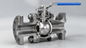
The ball valve’s core opening and closing element is a sphere with a through bore — the ball rotates 90 degrees to open or close, with the bore aligned with the pipeline for full flow and perpendicular to the pipeline for shutoff, and the sealing faces experience no relative sliding friction during the entire operation, which is the fundamental mechanical distinction between ball valves and gate valves or globe valves.
API 6D full-bore design makes the ball bore diameter equal to the pipe nominal inside diameter, allowing pipeline pigs to pass through without obstruction — this is a basic requirement for pipeline integrity management on offshore platforms and long-distance transmission lines, and it is also one of the core features that distinguish API 6D valves from standard industrial ball valves.
Forged ball valves are classified by bore size into full-bore and reduced-bore types — full-bore ball bore diameter equals the nominal size, with a flow resistance coefficient K approximately 0.01, the lowest of all industrial valves; reduced-bore bore diameter is one to two size steps smaller than the nominal size, reducing manufacturing cost by 15 to 25 percent, but full-flow operation incurs hundreds to thousands of dollars per year in additional energy costs from pressure drop, requiring a life-cycle cost analysis to determine economic viability.
Global annual forged ball valve shipments total approximately several million units, with the oil and gas sector accounting for over 60 percent of demand — this figure illustrates the irreplaceable role of forged ball valves in high-pressure oil and gas transmission and reflects the global energy infrastructure’s high dependence on valve reliability.
Forged vs Cast
Forging and casting are the two fundamental manufacturing processes for ball valve body forming — forging shapes metal blanks under 5,000 to 30,000 tons of hydraulic or hammer pressure, densifying and elongating metal grain structures along the valve profile direction, achieving tensile strength of 480 to 650 MPa with density of 99.5 percent or above.
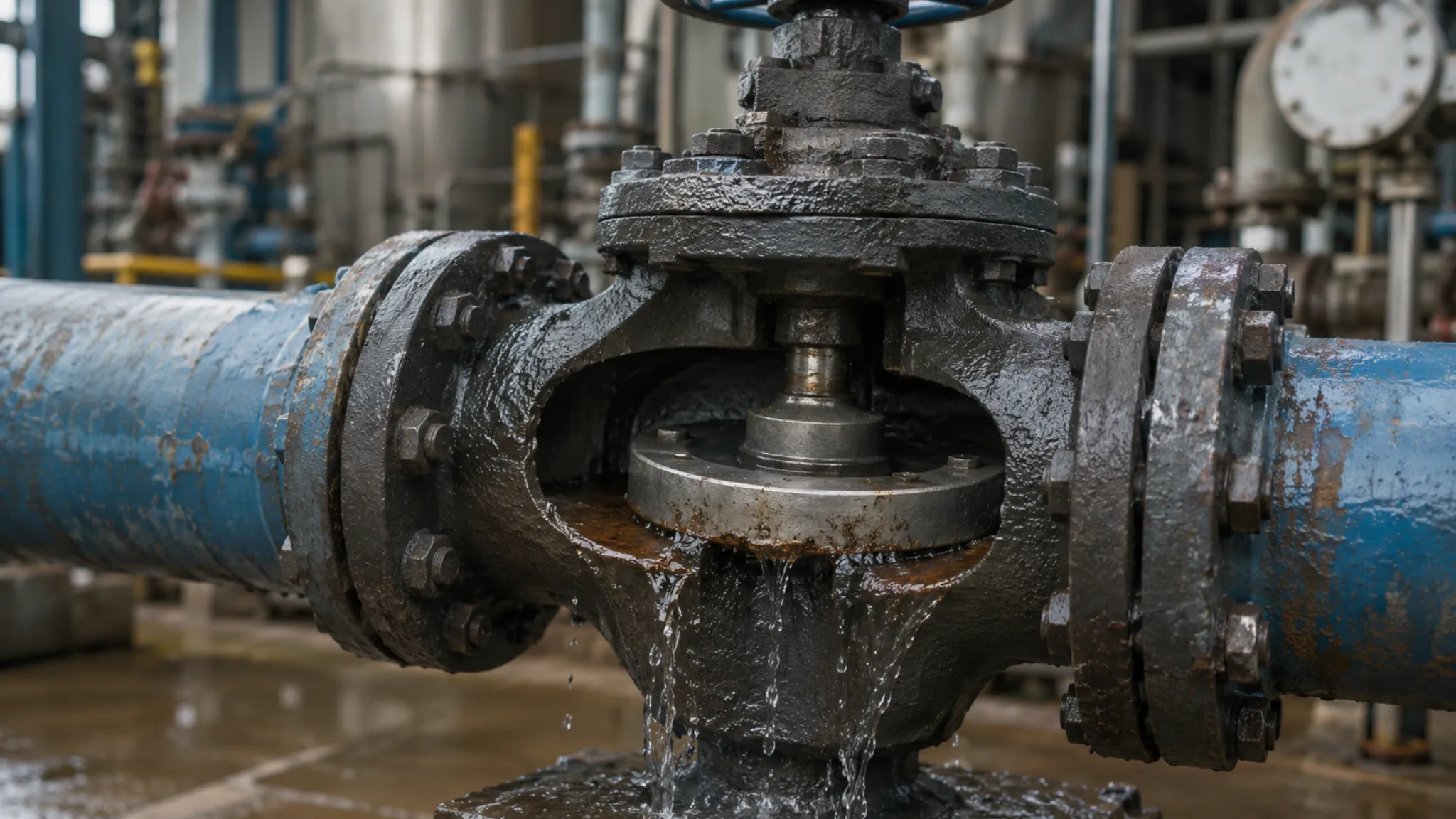
Casting pours molten metal into sand or metal molds to solidify and take shape — the solidification process inevitably produces shrinkage porosity, gas pores, and segregation, with an internal defect detection rate of approximately 5 to 8 percent in castings, meaning some microscopic defects may evolve into crack origins years into operation even after radiographic and ultrasonic inspection sampling.
The metallurgical difference directly manifests in fatigue performance — under identical stress levels, the fatigue limit of forgings is 30 to 50 percent higher than that of castings, and in Class 600 and above service with cyclic pressure exceeding 30 percent of design pressure, forged steel valve bodies operate reliably for over 15 years while cast steel valve bodies typically develop fatigue cracks within 5 to 8 years, because casting defects gradually propagate under cyclic stress to become crack initiation sites.
Body wall thickness uniformity is a hidden advantage of forged ball valves over cast steel — during solidification, non-uniform cooling rates in cast steel parts cause wall thickness variation, whereas forged parts shaped under high pressure have more uniform wall thickness distribution, smaller machining allowances, which saves both material and machining labor hours.
I once participated in the valve technical review for an offshore platform modification project — the original design used cast steel valve bodies, and during drawing review engineers discovered that some ball valve body wall thickness non-uniformity reached 15 percent, leading to a full switch to the same-specification forged steel valve bodies; despite an approximately 18 percent increase in procurement cost, this decision fundamentally eliminated the risk of casting pores evolving into leakage sources, and the platform’s subsequent operation fully validated this choice.
Main Benefits
Five interrelated structural and material advantages make forged ball valves the preferred choice for high-pressure and high-risk service — the first is high strength — forged metal yield strength exceeds that of cast metal by over 30 percent, and Class 600 and above pipelines almost universally employ forged ball valves; the second is reliable sealing — uniform forged body wall thickness makes seal face machining precision easier to achieve, and the double block and bleed function specified in API 6D is difficult to implement consistently on cast valve bodies.
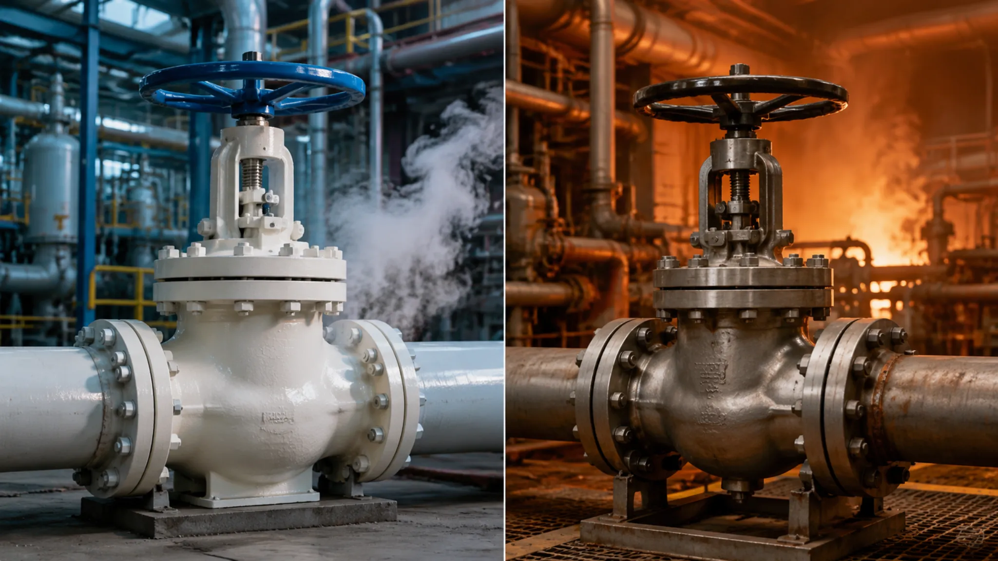
The third benefit is superior cryogenic performance — for the same material, the ductile-to-brittle transition temperature of forgings is 30 to 50 degrees Celsius lower than that of castings — LNG cryogenic service below minus 100 degrees Celsius mandates forged valve bodies, and the North Sea fracture case was a direct consequence of inadequate DBTT in cast steel.
The fourth benefit is strong resistance to stress corrosion cracking — forged valve bodies have no sand pores or microscopic voids, in H2S-containing sour oil and gas environments, stress corrosion cracking has fewer initiation sites and lower crack propagation rates, which is why acid gas fields such as Middle Eastern and North American shale gas projects almost universally specify forged ball valves.
The fifth benefit is superior dimensional stability — machined forged parts have uniformly distributed residual stress and minimal thermal deformation, with pre-load loss over 40 percent lower than castings during installation, providing higher long-term reliability for flange sealing, an advantage particularly pronounced in large-diameter ball valves above DN 300.
According to the Energy Institute 2022 technical report, casting defects account for approximately 12 percent of major valve leakage incidents at global oil and gas facilities, while forged ball valve leakage rates under identical conditions are below 1 percent — the difference in tensile strength and density is the most direct metallurgical reason behind these two figures.
Key Parts
The Body
The API 6D ball valve body is the first pressure-containing component that withstands pipeline pressure and fluid temperature — body materials are selected from three major categories based on design temperature and media corrosiveness — carbon steel A105 (minus 29 to plus 425 degrees Celsius, for sulfur-free oil and gas field surface facilities), chromium-molybdenum steel F22 (425 to 540 degrees Celsius, for refining high-temperature pipelines), and austenitic stainless steel F316 (minus 196 to 650 degrees Celsius, for LNG cryogenic and strongly corrosive media).
Body wall thickness is calculated per ASME B16.34 formulas — for a Class 600 DN 200 carbon steel valve body, typical wall thickness is approximately 22 to 28 millimeters; insufficient wall thickness causes yield deformation under high cyclic stress, while excessive thickness increases material cost and flange pre-load burden, and practical sizing should find the optimal balance between material cost and structural safety.
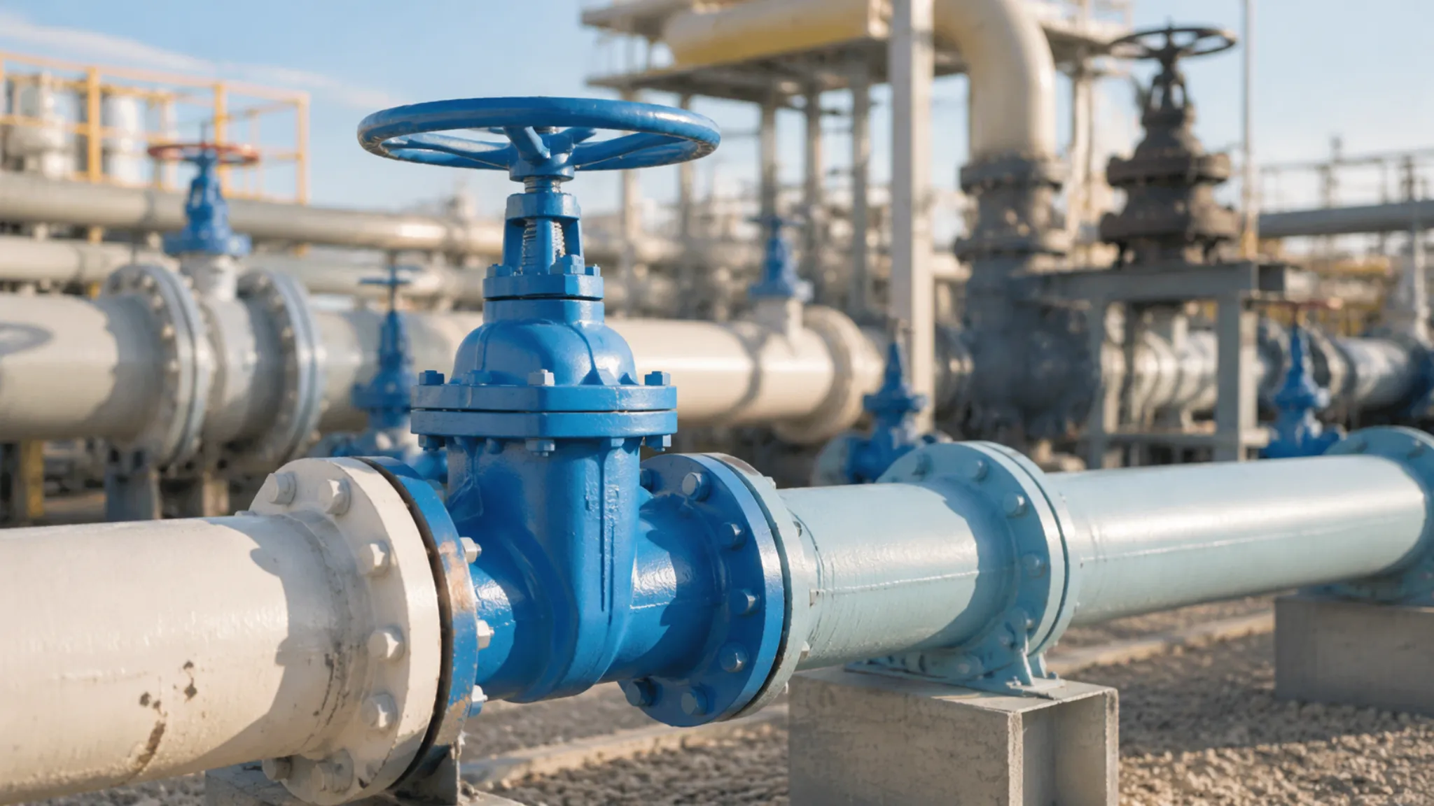
Body-to-pipeline connection uses flanged joints — raised face flanges suit general oil and gas field gathering systems, while ring joint face flanges are used for high-pressure wellhead installations at Class 900 to 1500, with metal-to-metal sealing providing higher reliability under high pressure and temperature; flange pressure class must match pipeline design pressure, which is the most fundamental sizing principle, and a Class 600 pipeline absolutely cannot use Class 300 flanges.
The vent and drain valves at both ends of API 6D ball valves constitute the core of the double block and bleed function — when the main ball valve requires online maintenance, alternating operation of upstream vent and downstream drain isolates and bleeds the media on both sides, allowing safe disassembly of the main valve with the pipeline still pressurized, which is one reason offshore platforms and long-distance pipelines must specify API 6D ball valves, and also the safety function difference that distinguishes them from standard industrial ball valves.
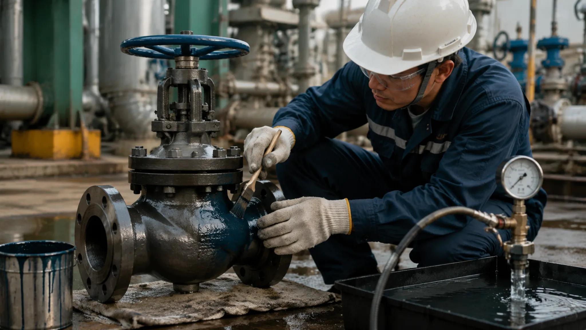
Body hydrostatic test pressure is 1.5 times the design pressure per API 6D requirements, and the valve may only ship after 30 minutes at test pressure with zero leakage — this is the final quality inspection before forged ball valve shipment and also the mandatory acceptance check item for incoming goods.
The Ball
The ball is the core opening and closing component of the ball valve — a full-bore ball bore diameter equals the pipe nominal inside diameter, with a flow resistance coefficient K approximately 0.01, the lowest of all industrial valves, which is the structural reason full-bore ball valves are the preferred choice for piggable pipelines and also the basic requirement for offshore platforms and long-distance transmission lines.
Ball materials are typically matched to or higher than body materials — carbon steel bodies paired with 316 stainless steel balls is the most common combination, since the ball is in direct contact with the media and its corrosion resistance should exceed that of the body; ball surface roughness requirement is Ra no greater than 0.8 micrometers, and excessive roughness damages the seat sealing face causing internal leakage, which is one of the common causes of ball valve seal failure.
Ball-to-stem connection uses key or spline connections, and the connection structure must incorporate anti-blow-out design — even if the stem packing completely fails, high-pressure media cannot blow the stem out of the body, which is one of the mandatory safety requirements for API 6D ball valves and is particularly critical in high-pressure gas service.
A DN 150 Class 600 ball valve unloaded open-close torque is approximately 25 to 40 newton-meters; pneumatic actuators typically select output torque specifications of 300 to 500 newton-meters, providing at least 8 times torque margin to ensure reliable operation even under harsh conditions of low temperature with increased lubricant viscosity or excessive differential pressure.
Ball polishing quality directly affects sealing performance — ball surface roughness Ra no greater than 0.8 micrometers is the basic API 6D requirement; excessive roughness grinds grooves into the seat causing internal leakage, precision polishing typically uses multi-stage grinding and diamond polishing compound, achieving final surface finish of Ra 0.2 to 0.4 micrometers.
Bore machining precision is another key indicator — bore concentricity error relative to the stem axis must be within 0.05 millimeters; out-of-tolerance causes seat uneven wear and non-uniform sealing face wear, which is an inspection item requiring special attention during ball valve manufacturing.
Seals and Seats
Seat diameter ranges from DN 50 to over DN 1000 — the ball valve sealing system consists of two independent subsystems, the sealing seat and the stem packing, with seat service temperatures from minus 196 degrees Celsius for PTFE material to plus 650 degrees Celsius for graphite material, covering the complete service temperature range from LNG cryogenic to refining high-temperature conditions.
The seat is the moving sealing face between the ball and the body — API 6D-recommended resilient seats use springs or fluid pressure behind the seat to keep the seat continuously pressed against the ball, achieving bidirectional sealing; seat materials are selected by temperature and media — RTFE for minus 30 to plus 200 degrees Celsius, graphite for 200 to 300 degrees Celsius, metal seats for abrasive media above 400 degrees Celsius.
Stem packing is the final barrier preventing internal media from leaking along the stem — graphite braided packing is the standard configuration, rated to 450 degrees Celsius; PTFE packing for LNG cryogenic pipelines from minus 196 to 260 degrees Celsius; thick carbon fiber packing for abrasive media containing solid particles; packing gland bolt torque is the key installation parameter — excessive torque increases stem operating torque and accelerates packing wear, while insufficient torque causes seal failure.
Measuring stem torque as a baseline value after new valve installation is the foundation of valve life-cycle management and the most effective means of preventing serious leakage — when stem torque increases more than 20 percent above the baseline, scheduled online packing maintenance should be arranged, which is the standard inspection threshold recommended in API 6D ball valve maintenance manuals.
I once handled a stem packing leakage incident — a DN 100 Class 600 ball valve developed visible seepage at the stem after six months in service; on-site measurement found stem torque had increased 40 percent compared to the new installation value, confirming packing compression relaxation; the station used an online packing replenishment method without shutdown, restoring torque near the baseline value and eliminating the leak, saving one planned outage.
How It Works
Open and Close
Ball valve opening and closing is accomplished by the stem driving the ball to rotate 90 degrees — the handle rotates 90 degrees or the actuator outputs torque to drive the stem, and the stem and ball rotate synchronously through key or spline connection, with the bore changing from aligned with the pipeline to perpendicular to the pipeline to achieve shutoff or flow; the engineering significance of this 90-degree rotation is that the valve has only two operating states — fully open and fully closed — and intermediate positions are only for emergency regulation and are not suitable for long-term operation.
The sealing mechanism during opening and closing is self-assisting — during closing, upstream pressure presses the seat more tightly against the ball, with sealing specific pressure increasing as operating pressure rises, which is the physical reason API 6D ball valves become more reliably sealed at high pressure; upon opening, upstream and downstream pressure differential slightly offsets the ball, reducing sealing face friction resistance, causing opening torque to typically run 10 to 20 percent lower than closing torque.
I once tested the open-close torque characteristics of a DN 150 Class 600 ball valve on site — manual closing torque was approximately 38 newton-meters, manual opening torque approximately 32 newton-meters, the 16 percent difference matching the pressure balance mechanism exactly; after installing a pneumatic actuator set to 400 newton-meters output torque providing 10 times margin, actual testing in a minus 20 degrees Celsius low-temperature environment showed smooth and reliable operation, validating the necessity of sufficient torque margin.
Ball valve opening and closing speed is particularly important in ESD emergency shutdown system applications — typical pneumatic actuator response time is 0.5 to 2 seconds, and for Class 600 and above high-pressure pipelines, excessively fast emergency closure generates water hammer as liquid decelerates instantaneously, causing pressure spikes; reasonably setting closure time typically between 1 and 5 seconds finds the balance between reliable shutoff and water hammer protection.
On-site torque measurement data is the baseline for valve health assessment — it is recommended to retest stem torque every six months and compare against the new installation baseline; when torque increases more than 25 percent above baseline, preventive maintenance should be scheduled to prevent packing failure from developing into external leakage incidents.
Controlling Flow
A DN 50 ball valve at 5 percent opening has local flow velocity that can reach 6 times normal pipeline velocity — a ball valve is fundamentally a rapid opening-closing valve, not designed for flow regulation; at partial opening, high-velocity fluid impingement on the ball bore inlet edge generates cavitation and erosion wear, and long-term throttling operation severely shortens ball valve service life and may even cause ball damage, which is the physical nature of why ball valves are unsuitable for throttling service.
Service requiring precise flow regulation should use specialized control valves — rotary control valves or linear single-seat valves — instead of ball valves; API 6D standard commentary explicitly states that long-term operation at partially open positions causes uneven specific pressure distribution on the seat sealing face, accelerating seal failure, and API 6D ball valve manufacturers typically explicitly state in technical documents that ball valves are not suitable for throttling service.
Ball valves have some practical utility within specific opening ranges — in emergency shutdown scenarios, rapidly closing from full open to 10 percent opening with pneumatic actuator response time of 0.5 to 2 seconds causes no significant damage to the ball valve, because the ball bore edge remains protected by fluid coverage at partial opening and is not directly exposed to high-velocity impingement, which is the physical basis for ball valves as ESD valves.
Ball valve flow coefficient or Cv value is a basic parameter in process engineering design — a full-bore DN 200 ball valve Cv is approximately 1800 to 2200, and compared to same-specification gate valves with Cv approximately 1400 and globe valves with Cv approximately 900, ball valves have the highest flow capacity, which is also the structural reason ball valves are the preferred choice for high-pressure large-diameter pipelines.
If ball valves must be used for flow regulation, controlling opening between 25 and 75 percent is recommended — in this range fluid impingement patterns are relatively stable and cavitation risk is lower than in extreme throttling conditions below 5 percent opening, but regular seat wear inspection is still necessary to prevent seal failure from extended throttling operation.
Where to Use
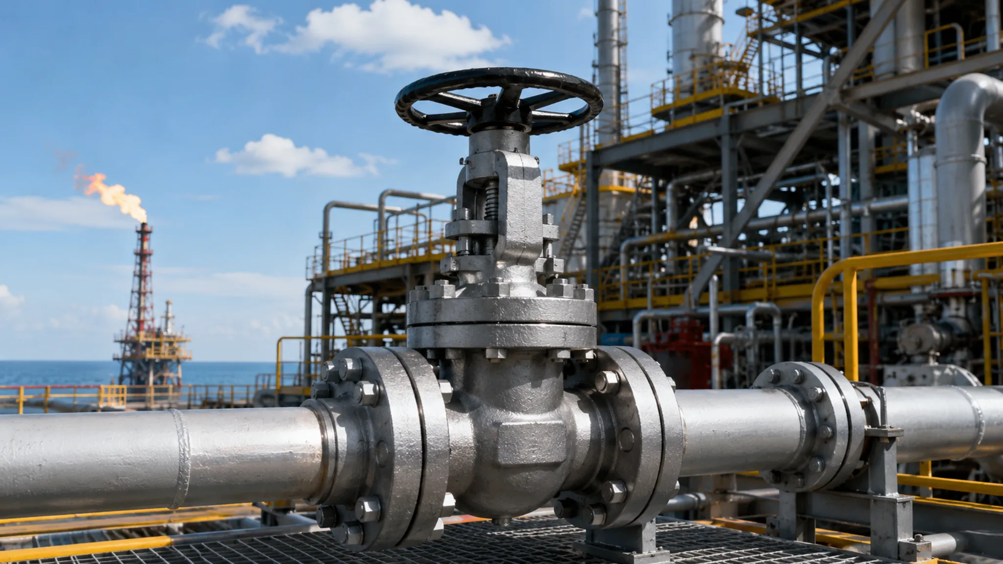
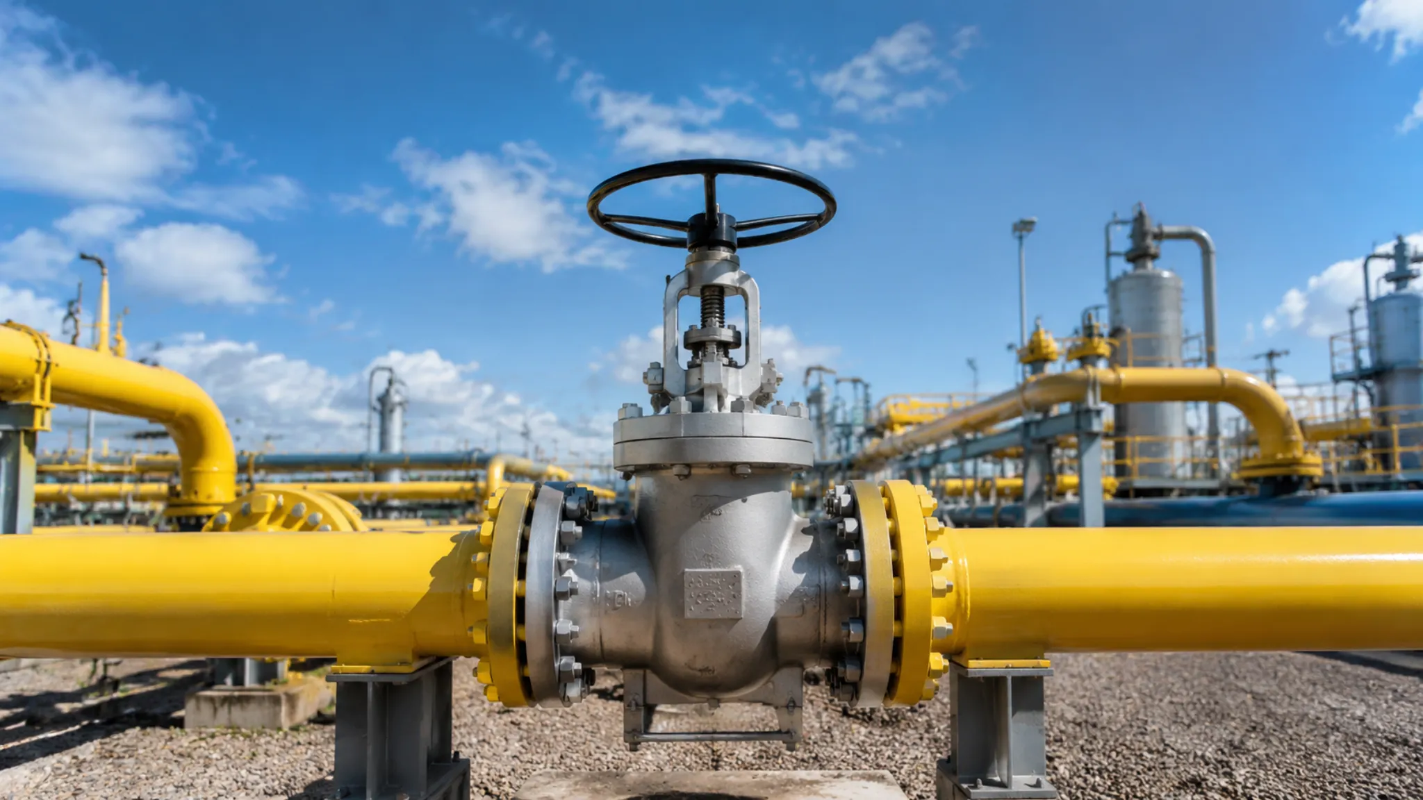
Oil and gas field gathering systems are the largest application area for forged ball valves — accounting for over 45 percent of global industrial ball valve market share, with single offshore platform oil and gas fields using 500 to 2000 ball valves; typical configurations are full-bore, carbon steel A105 body, 316 ball, RTFE seats, suitable for wellhead installations, metering stations, pigging stations, and station inlet and outlet pipelines across all scenarios, making them the standard configuration for oil and gas field surface facilities.
- Oil and gas field gathering: 45%+ market share, 500-2000 valves per platform
- Refinery and chemical plants: 30% usage rate, F22 body plus graphite seats standard
- LNG terminals: minus 162 degrees Celsius, F316 body with extended stem mandatory
Refinery and chemical plant main trunk pipelines use forged ball valves at approximately 30 percent — here high-temperature, high-pressure, and corrosive media service conditions are concentrated, requiring upgraded ball valve materials of F22 body plus graphite seats; Fire Safe configuration is a basic requirement in refineries, with API 607 fire test certification confirming the valve maintains basic sealing function under fire conditions, preventing secondary leakage incidents caused by fire.
LNG receiving terminals and liquefied natural gas plants are another core application scenario for forged ball valves — LNG pipeline temperature is as low as minus 162 degrees Celsius, mandating F316 stainless steel body and PTFE packing; the defining feature of LNG ball valves is the cryogenic stem extension design, isolating the actuator from the ultra-cold ball, ensuring the actuator operates within normal temperature range, which is the design characteristic distinguishing LNG ball valves from standard ball valves.
I once visited the valve spare parts warehouse of an LNG receiving terminal — the site technical manager told me that their spare parts inventory included three times as many forged ball valve SKUs as cast steel ball valve SKUs, which illustrates from one perspective the LNG industry’s high dependence on forged ball valve reliability, and validates our insistence on material grade selection during the sizing phase.
API 6D standard, 24th edition, specifies that forged ball valve body materials must pass tensile testing and impact testing with Charpy V-notch specimens, with impact test temperature no lower than minimum design temperature and impact energy no less than 27 joules — these three sets of testing data constitute the most fundamental metallurgical basis distinguishing forged steel from ordinary cast steel.
Energy Institute 2022 technical report statistics show that casting defects account for approximately 12 percent of major valve leakage incidents at global oil and gas facilities, while forged ball valve leakage rates under identical conditions are below 1 percent — the difference in tensile strength and density is the most direct physical reason behind these two figures.
ASME B16.34 standard specifies the calculation method for ball valve body wall thickness: minimum wall thickness must satisfy stress requirements under design pressure while considering temperature derating and corrosion allowance — body wall thickness calculation is the first step in ball valve selection.
SPE 2023 paper data shows that approximately 28 percent of offshore platform ball valve failures are related to stem packing leakage, and over 60 percent of these can be attributed to insufficient initial installation torque or improper packing selection — these two percentages illustrate that packing selection and installation are the most controllable factors in ball valve reliability.
| Comparison Dimension | Forged Ball Valve | Cast Steel Ball Valve |
|---|---|---|
| Manufacturing Process | High-pressure forging densification | Molten metal solidification forming |
| Tensile Strength | 480-650 MPa | 380-550 MPa |
| Grain Structure | Continuous dense structure along profile | No directionality, shrinkage porosity and gas pores present |
| Density | 99.5% or above | 97%-98.5% |
| Fatigue Life | 30%-50% higher than castings | Shorter life under identical stress |
| Low-Temperature Toughness | DBTT significantly lower than castings | Brittleness risk below minus 30 degrees Celsius |
| Manufacturing Cost | 15%-25% higher | Relatively lower |
| Typical Application | High-pressure, high-risk, cryogenic critical pipelines | General service, auxiliary pipelines |
Forged ball valve selection always begins with confirming nominal size and pressure class — these two parameters determine body wall thickness, material service temperature range, and pricing tier, which form the foundation for all subsequent configuration choices; regardless of how complex the service conditions, the API 6D forged ball valve selection logic always starts from these two parameters.

")