
Floating ball valves are among the most widely used isolation valves in oil and gas, chemical, and pipeline systems. Compared to trunnion ball valves, floating ball valves feature a simpler structure and lower cost, with reliable sealing performance in low-to-medium pressure ranges. This guide covers three core dimensions—**working principle**, **pressure rating**, and **API 6D standard**—to help engineers and procurement professionals quickly master proper selection methods.
How It Works
How the Ball Moves
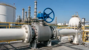
The core component of a floating ball valve is a stainless steel ball that floats freely within the valve body. The ball is welded to the top of the stem, with no fixed support at the bottom—this is the fundamental distinction between floating and trunnion ball valves. When an operator turns the handwheel or actuator, the stem rotates the ball 90° around the valve body centerline, aligning or blocking the ball’s bore with the pipeline flow path to open or close the valve.
The stem-to-ball connection uses an Anti-Blow-Out design: a shoulder on the lower end of the stem fits into a groove in the top of the ball, preventing the stem from being ejected even if internal pressure surges. API 6D mandates this anti-blow-out stem structure for all ball valves as a mandatory factory inspection item. Additionally, API 6D requires anti-static devices (spring-loaded contacts ensuring electrical continuity between the ball and body) to prevent static discharge sparks—a critical requirement for flammable media systems.
Graphite gaskets and O-rings in the middle of the stem provide dual sealing to prevent process media from leaking along the stem gap. Typical operating torque (DN50, PN16): manual operation approximately 15–25 Nm; pneumatic actuator approximately 30–60 Nm. At higher pressure ratings (Class 600), torque for the same bore can rise to 80–120 Nm because high differential pressure significantly increases contact stress between the ball and seat. During selection, ensure the actuator output torque exceeds the valve’s maximum operating torque with at least 25% safety margin.
How It Seals
The sealing mechanism of a floating ball valve relies on the combined action of pipeline pressure and seat spring force. When the valve is closed, process media pressure acts on the downstream side of the ball, pushing it against the downstream seat. The downstream seat is fixed in a valve body groove and cannot move, so the ball and seat make precise contact to form a seal. There is a key positive feedback relationship: the greater the differential pressure across the valve, the stronger the force pushing the ball against the seat—the seal actually improves under high differential pressure, which is the fundamental reason floating ball valves perform better in high-differential-pressure conditions than in low-pressure applications.
Seats are typically made of reinforced PTFE (polytetrafluoroethylene) or flexible graphite. PTFE seats operate from -196°C to +260°C and resist most acids, alkalis, and solvents, but are unsuitable for abrasive media—solid particles embedded in the PTFE sealing surface cause abrasive wear that accelerates seal failure. Flexible graphite seats withstand up to +600°C and are commonly used in steam or hot oil systems. A stainless steel spring behind the seat provides initial preload force, ensuring the valve maintains basic sealing even when the pipeline is unpressurized or at low pressure.
Sealing between the valve body and ball is achieved through the stem bonnet. Graphite rings or PTFE V-ring packs are common packing materials. Both API 6D and API 608 require stem packing to show no visible leakage under normal operating temperatures. When differential pressure exceeds the seat material’s pressure limit, sealing fails—which is precisely why pressure rating must be strictly verified during selection. Anti-static design is equally critical: API 6D requires contact resistance between the ball and body to not exceed 10Ω to prevent static discharge ignition.
Fluid Flow Basics
Floating ball valve flow paths come in two configurations: Full Bore (FB) and Reduced Bore (RB). A full bore valve’s ball bore matches the pipeline nominal bore, allowing unrestricted media flow with minimal resistance—ideal for pipelines requiring periodic pigging. A reduced bore valve’s ball bore is one or two sizes smaller than the pipeline nominal bore (e.g., DN100 pipeline with a DN80 valve), offering lower manufacturing cost but greater pressure drop; it is unsuitable for high-flow or solid-laden media.
The flow coefficient (Cv value) is the key parameter for evaluating a ball valve’s flow capacity. Cv is defined as the flow rate of 60°F water (in US gal/min) at a 1 psi pressure differential across the valve. A full bore DN50 ball valve typically has a Cv of approximately 35–45; a reduced bore DN50 (for DN80 pipeline) has a Cv of approximately 18–25. During selection, calculate the required Cv using the formula Q = Cv × √(ΔP/SG), where SG is specific gravity, then select a valve with a rated Cv exceeding the calculated value. An undersized Cv will cause pipeline pressure drop to exceed the design value, degrading pump performance and process efficiency.
For applications with high cavitation risk (high-differential-pressure liquid systems), the valve’s cavitation index (CAV) must be calculated. When CAV exceeds the critical value, liquid vaporizes locally within the valve, forming bubbles that collapse and generate high-speed micro-jets that erode the seat and body surface. Common mitigation measures include multi-stage pressure-reduction trim, upsizing the valve to reduce velocity, or installing a surge tank upstream. API 608 specifies the Cv testing method; different manufacturers may have slightly different Cv values for the same valve size, so always prioritize the manufacturer’s factory-tested data during selection.
Pressure Rating Limits
Standard Pressure Classes
Floating ball valve pressure ratings are determined by design standards and material strength. Two classification systems are globally dominant: the **American standard Class system** (derived from ASME B16.34) with common classes including 150, 300, 600, 900, 1500, and 2500, corresponding to Maximum Allowable Working Pressure (MAWP) at 38°C. For carbon steel WCB bodies: Class 150 ≈ 1.96 MPa (285 psi); Class 300 ≈ 5.1 MPa (740 psi); Class 600 ≈ 10.3 MPa (1490 psi). Stainless steel (CF8M) bodies typically carry 10%–15% higher pressure ratings than carbon steel at equivalent class.
The **European PN system** uses PN10, PN16, PN25, PN40, PN63, and PN100, where the PN value approximately equals the MAWP at 38°C in bar. PN16 ≈ Class 150; PN40 ≈ Class 300; PN100 ≈ Class 600. In the Chinese market, both PN and Class systems coexist. During selection, confirm that the valve nameplate matches the pipeline design pressure—for a design pressure of 1.6 MPa, prefer PN16 (more precise); for 4.0 MPa, select PN40 rather than Class 300 (PN40 = 4.0 MPa).
For valves of the same nominal size, higher Class ratings require thicker body walls, and flange thickness and bolt hole specifications increase accordingly. Class 150 and Class 300 flanges share the same dimensions, but Class 300 bodies are significantly thicker to withstand higher pressure; Class 600 flanges are typically one grade thicker than Class 300, with potentially more bolts. Confusing Class ratings may cause flange mismatches or valve bodies unable to withstand actual working pressure, leading to serious safety incidents. In practice, ball valves rated Class 600 and above typically require reinforced actuator mounting brackets and rigid piping connections to handle the greater reaction torque from high-differential-pressure operation.
High Pressure Risks
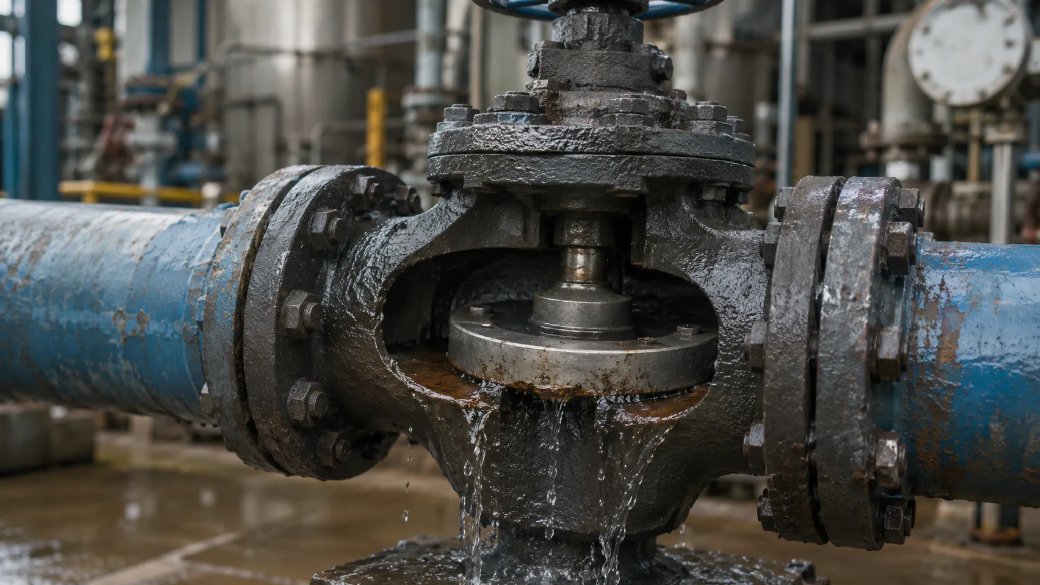
Operating above a valve’s rated pressure triggers a chain of serious consequences. When internal pressure exceeds the seat material’s elastic limit, the seat deforms permanently, and the sealing face cannot restore its original geometry—resulting in internal leakage in the closed position. Severe overpressure causes yielding deformation of the valve body, destroying concentricity between the ball and seat and completely eliminating sealing ability. API 6D explicitly prohibits valve operation above nameplate pressure and requires warning labels on factory documentation.
Overpressure affects the valve body in three primary ways: body deformation (thin-wall areas bulge outward under sustained high pressure, forming irreversible plastic deformation); joint failure (flange sealing faces warp or bolt stress relaxes under high pressure, causing external leakage); and accelerated seal aging (high differential pressure keeps the seat under sustained high contact stress, dramatically accelerating creep and cold flow in soft sealing materials like PTFE, shortening service life significantly).
For pipelines carrying solid particles or water, high differential pressure intensifies erosion risk. Solid particles accelerated by high pressure through the seat sealing surface cause abrasive wear on the soft sealing material. API 6D explicitly requires that gas field valves handling solid-laden media must have particle concentration and size distribution stated in the contract so manufacturers can specify reinforced wear-resistant seat designs. Water hammer is another risk in high-differential-pressure pipelines: rapid valve closure causes inertial fluid to strike the valve body, generating transient pressure spikes that may exceed the valve’s rated pressure and cause damage.
Finding Safe Limits
Determining safe operating pressure requires considering three core parameters: valve nameplate pressure (Rated Pressure), pipeline design pressure (Design Pressure), and Maximum Allowable Working Pressure (MAWP). The relationship is: nameplate pressure ≥ design pressure, and actual operating pressure must be strictly below design pressure with adequate safety margin (typically ≥1.3×). API 6D requires valve nameplates to display both pressure rating and applicable temperature range—these cannot be used separately.
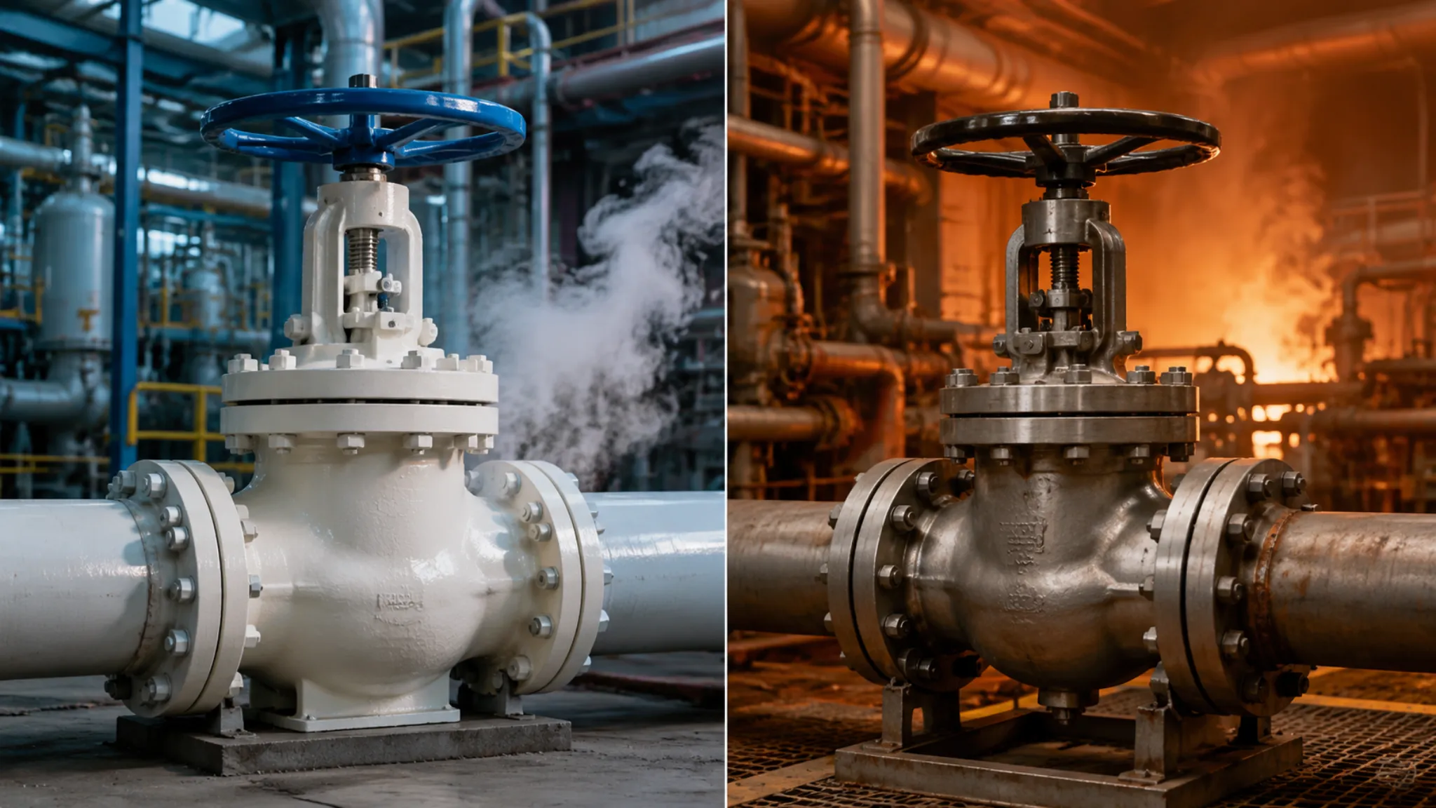
Temperature’s effect on pressure rating is critical. ASME B16.34 provides comprehensive Pressure-Temperature (P-T) tables: as medium temperature rises, allowable working pressure for the same Class valve decreases progressively. For a carbon steel WCB Class 150 valve: MAWP is 1.96 MPa at 38°C; drops to approximately 1.73 MPa at 200°C; to approximately 1.03 MPa at 260°C; to approximately 0.62 MPa at 370°C. Using a valve at its 38°C rated pressure in a high-temperature application constitutes serious overpressure.
During selection, determine both Maximum Working Pressure (MWP) and Maximum Working Temperature (MWT) and cross-reference the P-T table to find the appropriate pressure class. For combined high-temperature and high-pressure conditions (e.g., superheated steam systems), consult the valve manufacturer directly for the actual allowable pressure at the target temperature rather than applying the 38°C nominal rating. For hydrogen-containing pipelines, also refer to NACE MR0175/ISO 15156 for material hydrogen embrittlement sensitivity, and clearly specify hydrogen partial pressure and H₂S concentration when requesting manufacturer confirmation.
API 6D Rules
Why It Matters
API 6D is the most critical valve product standard for global oil and gas pipeline systems, published by the American Petroleum Institute (API), covering design, manufacturing, materials, testing, and delivery requirements for pipeline ball valves, gate valves, globe valves, and other valve types. API 6D has been adopted as an equivalent standard by ISO (as ISO 14313), referenced by Chinese national standards GB/T 19672, and serves as the foundational document for bidding and technical negotiations in domestic and international pipeline projects. Major global oil companies (Shell, ExxonMobil, Saudi Aramco, etc.) all use API 6D as the minimum threshold in their company standards, adding supplementary requirements on top.
API 6D compliance means the valve undergoes full-process quality control from raw material to factory shipment. The standard specifies rigorous requirements for chemical composition, mechanical properties, heat treatment processes, non-destructive testing (NDT), pressure testing, and other critical processes, mandating that manufacturers establish traceable quality systems. API 6D requires that pressure-containing components—body, bonnet, ball, stem, and others—must have material traceability to heat numbers, heat treatment parameters must be documented, and NDT personnel must hold valid certifications.
In international pipeline projects, API 6D certification is a threshold condition for bid participation. Buyers typically state in Requests for Quotation (RFQ) that submitted valves must comply with API 6D and require manufacturers to provide API 6D product license or API monogram authorization certificates. API monogram authorization means the product has passed API factory audit and quality system evaluation and is permitted to bear the API official mark on the product. Valves without API 6D certification are effectively excluded from mainstream supplier lists in major oil and gas markets such as the Middle East and Southeast Asia.
Required Valve Tests
API 6D (together with API 598 inspection and testing standard) mandates five types of tests for every ball valve before shipment: Shell Test, High-Pressure Gas Seat Test, Low-Pressure Air Seat Test, Backseat Test, and Stem Blow-Out Test. Shell test pressure is 1.5× the MAWP at 38°C; hold duration follows API 6D Table 10—minimum 5 minutes for DN15–DN100, minimum 10 minutes for DN150–DN300, minimum 15 minutes for DN350 and above.
Seat tests are the core step for inspecting valve intrinsic quality. Upstream and downstream seats must each be pressure tested separately; leakage rate must not exceed API 598 limits (generally ≤50 Pa·m³/s or equivalent bubble count per minute). Gas seat testing is more stringent than liquid testing and effectively detects micro-porosity defects—it is mandatory for high-pressure gas pipeline valves. Test medium is typically nitrogen or clean dry air; hold duration matches shell test requirements.
For Fire-Safe ball valves, API 607 or API 6FA fire test certification is also required, verifying that the valve maintains sealing capability for a specified duration (typically minimum 30 minutes) under fire conditions, with post-fire external leakage not exceeding API 607 limits. Cryogenic valves (LNG service, etc.) require additional cryogenic testing, verifying functional integrity of all valve components at -196°C or below. API 6D mandates that cryogenic valve test temperature must be at least 5°C below the design minimum temperature; test medium is liquid nitrogen or a liquid nitrogen-alcohol mixture.
Selection Steps
Based on all sections of this guide, the standard selection process for floating ball valves can be summarized into six steps:
- Step 1 – Define operating parameters: collect medium name, inlet pressure, outlet pressure (or allowable pressure drop), operating temperature, flow rate requirements, and particle content; compile a Master Requirements Specification (MRS).
- Step 2 – Determine pressure class: use design pressure as the baseline, consult ASME B16.34 P-T tables, confirm the Class or PN class that satisfies the maximum operating temperature, ensuring nameplate pressure ≥ design pressure × safety factor (typically ≥1.3).
- Step 3 – Select body material: based on media corrosiveness and temperature, determine body and ball material (carbon steel WCB, stainless steel CF8M, duplex stainless steel 2205, etc.), ensuring alloy element compatibility with the service environment.
- Step 4 – Select sealing material: based on operating temperature and media compatibility, choose seat and stem packing material—PTFE (-196 to +260°C, general service), graphite (+600°C, steam/hot oil), or metal seats (high pressure/ temperature/abrasive service).
- Step 5 – Determine bore and configuration: based on Cv calculation and pigging requirements, decide between full bore (FB) and reduced bore (RB); confirm connection type (flanged/welded/threaded) and actuator interface (handwheel/gearbox/pneumatic/electric).
- Step 6 – Verify API 6D compliance: check manufacturer’s API monogram authorization, confirm factory inspection scope (shell test + seat test + fire test if applicable), and request Material Test Reports (MTR/Mill Test Reports) and test certificates.
Completing these six steps ensures the selected floating ball valve satisfies pipeline operating requirements across three dimensions: technical parameters, material compatibility, and standards compliance. For special applications (high-temperature/high-pressure gas fields, highly corrosive media, subsea pipelines, etc.), it is recommended to engage directly with the valve manufacturer’s technical team during the selection phase and obtain written selection confirmation with the manufacturer’s technical endorsement and warranty responsibility.
Understanding how the ball opens and closes, how sealing is achieved, and how pressure classes are translated are fundamental competencies for process engineers and procurement professionals. API 6D provides a verifiable baseline for valve quality, and the six-step selection process is the most effective tool for avoiding engineering incidents and controlling procurement risk.

")