
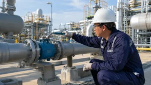
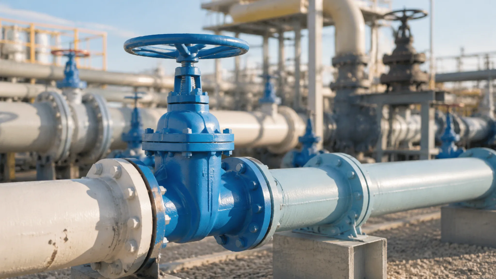
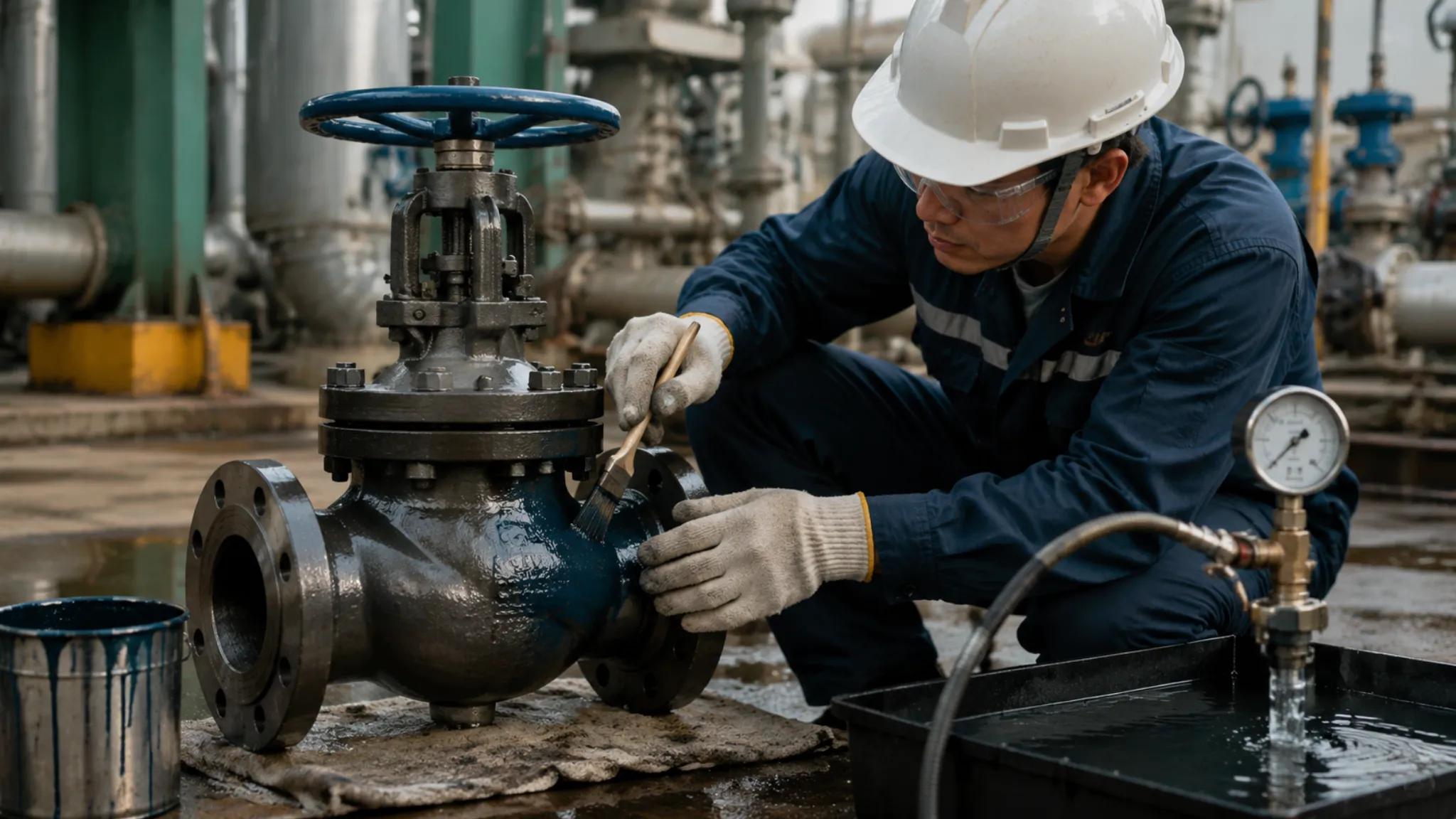
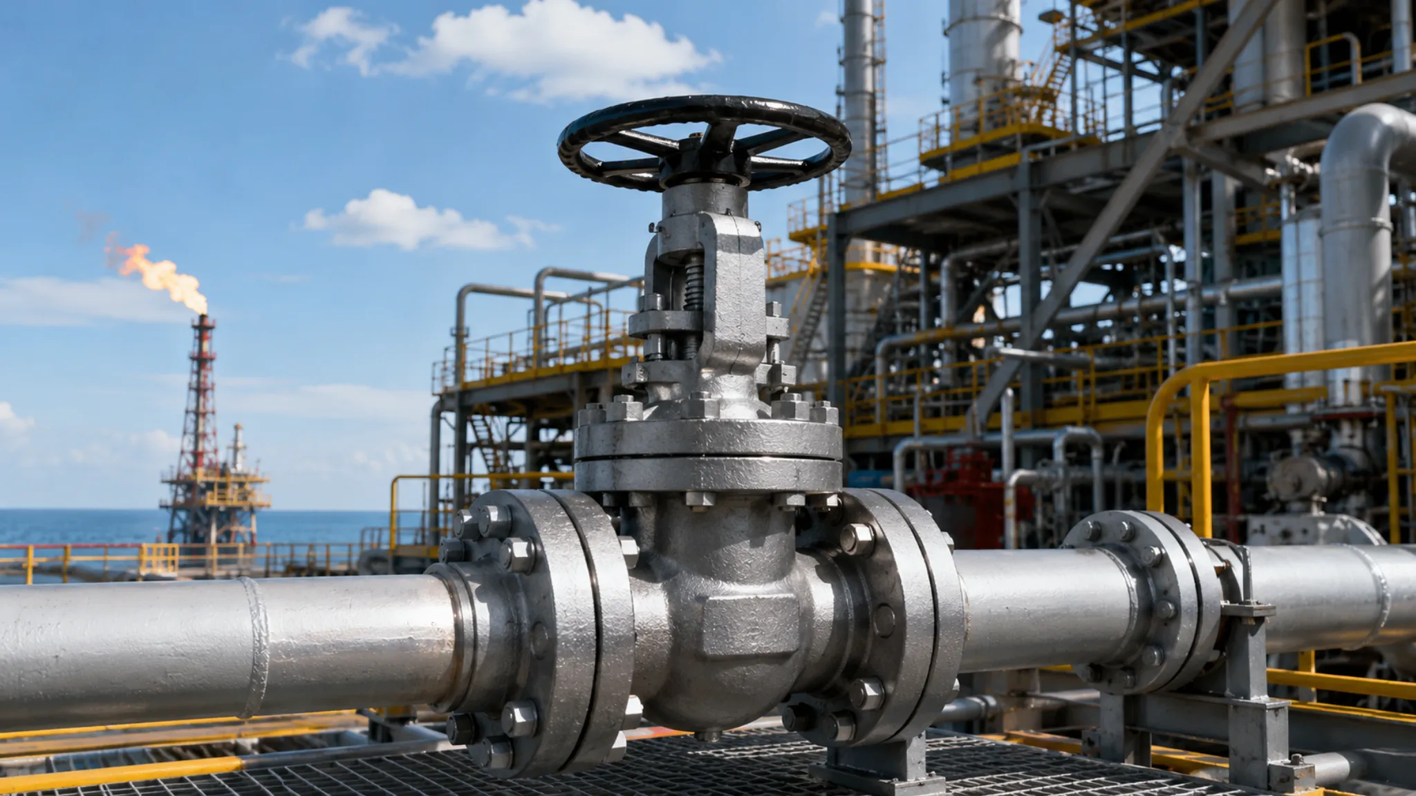
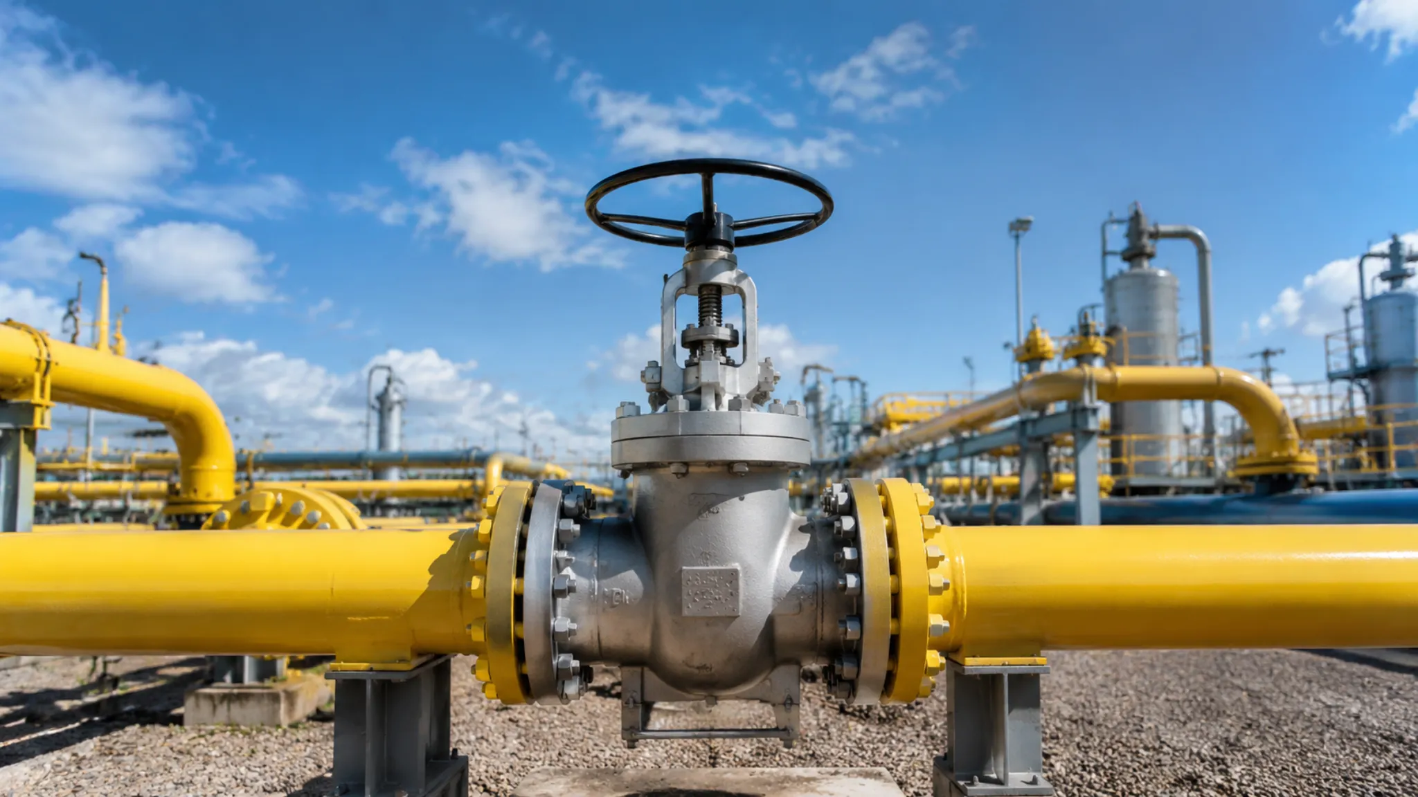
Floating ball valves are among the most widely used valve types in industrial fluid control systems, serving applications across oil and gas, power generation, chemical processing, and pulp and paper industries. Unlike trunnion-mounted ball valves where the ball is mechanically fixed in position, a floating ball valve’s ball sits freely and is pressed against the downstream seat by medium pressure to form a seal when closed. This design delivers low operating torque, reliable sealing, smooth flow channels, and minimal pressure loss. However, incorrect selection can lead to insufficient flow capacity, seal failure, seat corrosion, or even complete valve failure. Mastering the key selection criteria across three dimensions—Cv value, media compatibility, and seat material—is an essential skill for every process engineer and procurement professional.
Understanding Cv Value
What Cv Means
The Cv value (flow coefficient) is the internationally recognized metric for a valve’s flow capacity. It is defined as the number of U.S. gallons of 60°F water that flows through the valve per minute (GPM) when the pressure differential across the valve is 1 psi. A higher Cv value means the valve can pass a larger flow rate under the same pressure drop. A full-bore floating ball valve’s Cv value approaches the theoretical flow capacity of a same-size pipe bore, since the ball port diameter is essentially equal to the pipe ID, providing a smooth, uninterrupted flow path.
A reduced-bore ball valve’s Cv value decreases according to the square of the bore reduction ratio. Fluid must accelerate through the reduced cross-section to maintain the same mass flow rate, consuming additional energy in the process. In engineering practice, a Cv value that is too low creates severe throttling losses and noise, forcing the valve to operate at a smaller opening and wasting energy; a Cv value that is too wide narrows the valve’s controllable range and degrades regulation accuracy. Accurately calculating and properly selecting the Cv value is therefore the first critical step in valve sizing, directly affecting capital investment and operating costs across the entire loop.
Sizing Your Valve
The standard formula for valve Cv sizing, as recommended by the International Society of Automation (ISA), is: Q = Cv × √(ΔP / SG), where Q is the design flow rate (GPM), ΔP is the pressure drop across the fully open valve (psi), and SG is the specific gravity of the fluid (with water at 60°F defined as SG = 1.0). This formula is widely applied across process industries including oil and gas, chemical processing, and pharmaceuticals.
The sizing procedure typically follows four steps. First, determine the design flow rate and normal flow rate from the process PID. Second, establish the maximum allowable pressure drop based on pipe layout and pump head curves. Third, substitute these parameters into the formula to calculate the required Cv range. Fourth, select a valve with a Cv value equal to or slightly greater than the calculated value from the manufacturer’s valve data sheets. A critical note: ΔP must be the actual pressure drop at full-open conditions, not the rated working pressure. Using the pipe design pressure as a substitute for pressure drop is one of the most common sizing errors in practice.
Example: A water injection system requires a design flow rate of 200 GPM with an allowable valve pressure drop of 10 psi and water as the medium (SG = 1.0). Substituting into the formula gives Cv ≈ 63.2, so a full-bore floating ball valve with Cv ≥ 65 should be selected. If the selected Cv were only 40, the valve would be unable to meet the design flow requirement even at full open, requiring either additional pump head or upsizing the pipeline.
Avoiding Flow Drop
Although floating ball valves are designed for minimal flow resistance in the full-open position, multiple factors in actual operation can reduce the effective flow coefficient. Engineers must account for these risks during selection and installation.
- Reduced-bore design: When the ball port diameter is reduced to 70%~80% of the pipe bore, the Cv value drops to 40%~60% of full bore, while the restricted port generates high-velocity jets that accelerate seat wear and cavitation damage.
- Non-uniform upstream flow field: When a valve is installed on a pipe section with upstream elbows, tees, or other fittings, the incoming flow velocity profile is uneven, causing the actual Cv value to fall below the manufacturer’s stated rating. ISA recommends a minimum upstream straight pipe length of 5~10 pipe diameters.
- Protruding seat: In older valve designs, the seat sealing face may protrude above the pipe inner wall, generating local turbulence and eddies that consume additional fluid kinetic energy. Modern floating ball valve designs have largely eliminated this issue through flush-seat configurations.
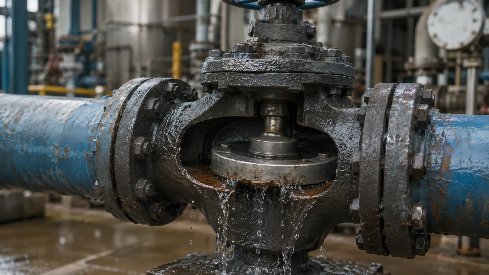
- Particle deposition and abrasive wear: Long-term erosion by sandy, waxy, or fibrous media progressively alters the geometry of the seat and ball sealing faces. Early symptoms include increased leakage rate; advanced stages can result in complete seal failure.
Checking Fluid Compatibility
Matching Chemical Types
The chemical composition and concentration of the process medium is the primary basis for determining valve material specifications. Engineers must establish a systematic compatibility analysis rather than relying on experience or brand preference alone. Hydrocarbons commonly encountered in oil and gas—crude oil, natural gas, diesel, gasoline, and aviation turbine fuel—are chemically inert to most metallic materials (carbon steel, stainless steel, alloy steel) and do not cause corrosion or stress corrosion cracking. However, these media can cause swelling in soft sealing materials; low-molecular-weight hydrocarbons such as liquefied petroleum gas (LPG) can penetrate the PTFE molecular structure, causing the seat to soften, reduce sealing force, or even fail.
The corrosion behavior of acids is far more complex. Take sulfuric acid as an example: below 70% concentration at room temperature, dilute sulfuric acid exhibits moderate corrosiveness to 316 stainless steel (corrosion rate approximately 0.5 mm/year), requiring regular wall thickness inspection; above 70% concentration at room temperature, concentrated sulfuric acid actually causes minimal corrosion to 316 stainless steel due to passivation of the steel surface; however, once temperature rises above 60°C, sulfuric acid at all concentrations severely attacks stainless steel. Hydrofluoric acid (HF) is perhaps the most challenging corrosive medium—it can dissolve virtually all silicate materials, leaving PTFE fully encapsulated seats or Hastelloy valve bodies as the only viable options.
Handling Thick Liquids
High-viscosity media and high-concentration slurries present special challenges for floating ball valves and must be fully considered at the selection stage. The flow resistance of highly viscous liquids—such as heavy fuel oil, asphalt, silicone oil, and syrup—increases dramatically with viscosity, causing the valve opening and closing torque to multiply accordingly. Consider a refinery case: a floating ball valve on a heavy oil pipeline operated normally during summer but experienced actuator overload protection trips in winter when heavy oil viscosity tripled, forcing conversion to a pneumatic actuator drive.
Slurries containing solid particles—ore slurries, paper pulp, sewage treatment sludge, and drilling mud—impose mechanical abrasive wear on the seats. The soft sealing seat of a floating ball valve is easily embedded with hard particles, forming abrasive wear tracks. Over extended operation, the flatness of the sealing face deteriorates and the leakage rate progressively increases. The recommended engineering response is: select hardened seats (such as hard-chrome-plated metal seats or tungsten carbide overlaid seats) based on particle hardness, and install a filter upstream of the valve to reduce solid content entering the valve chamber.
Preventing Valve Rust
Valve body corrosion is one of the most common failure modes in industrial plants, fundamentally caused by electrochemical reactions between metallic materials and corrosive media. Carbon steel (WCB) is one of the most common floating ball valve body materials, valued for low cost and high mechanical strength, but susceptible to uniform corrosion or pitting in humid atmospheres, acidic media, or oxygenated water.
Stainless steel resists corrosion through a passive chromium oxide film—Type 304 stainless steel performs well in clean atmospheric and freshwater environments but is prone to pitting and crevice corrosion in chloride-containing environments such as seawater or salt spray; Type 316 stainless steel, with 2%~3% molybdenum added, offers significantly better pitting resistance and is preferred for marine atmospheres and saline water media.
For extreme corrosive conditions (strong acids, strong alkalis, high-temperature chloride solutions), duplex stainless steel 2205 (22% Cr, 5% Ni, 3% Mo) or nickel-base alloys such as Hastelloy C-276 may be selected, at 3~5 times the cost of 316 stainless steel. Additionally, the valve stem must feature a blow-out-proof design—meaning the stem is captured from inside the body by a retaining ring—so that even if the actuator fails and applies abnormal thrust to the stem, it cannot be blown out by medium pressure, preventing catastrophic leakage.
Choosing Seat Materials
Soft vs Hard Seats
Seat material selection directly determines a valve’s sealing performance, applicable temperature range, pressure rating, and service life. Based on their sealing mechanism, seats are divided into two major categories: soft sealing and hard sealing. Soft seats, centered on PTFE (polytetrafluoroethylene) and its modified compounds, offer extremely low friction coefficients and outstanding chemical inertness, resisting attack from virtually all industrial media.
The advantages of soft seats include: high sealing class (achievable to ISO 5208 Class A or API 608 Fire Safe standards), low operating torque, easy maintenance, and moderate cost. Their limitations are: maximum operating temperature constrained by the material’s thermal stability, potential creep deformation (Creep) under high differential pressure, and inability to withstand hard particle abrasive wear. Floating ball valves predominantly use soft sealing designs—a key structural feature distinguishing them from trunnion-mounted ball valves, which commonly employ metal seats. Hard seats, relying on precision-ground metal sealing faces for line-contact sealing, can withstand higher temperatures and pressures, but require substantially greater operating torque and extremely tight surface roughness control (typically Ra≤0.2μm).
Heat and Pressure Limits
The Pressure-Temperature (P-T) rating of the seat material is a non-negotiable constraint in valve selection—operating beyond the rated range leads to rapid seat failure or safety incidents. The table below summarizes performance data for mainstream seat materials:
| Material | Abbreviation | Max Continuous Operating Temp | Typical Pressure Rating | Key Advantages |
| Pure PTFE | PTFE | 260°C (500°F) | PN16~PN40 | Widest chemical inertness; resists nearly all media |
| Carbon Fiber Reinforced PTFE | RPTFE | 300°C (572°F) | PN25~PN100 | Higher strength and creep resistance |
| Polyether Ether Ketone | PEEK | 200°C (392°F) continuous | PN64~PN160 | High strength, high wear resistance, chemical resistant |
| TFM-1600 | TFM | 250°C (482°F) | PN16~PN64 | Modified PTFE; low permeability |
| PCTFE | PCTFE | 150°C (302°F) | PN16~PN40 | Outstanding low-temperature performance; remains flexible at -200°C |
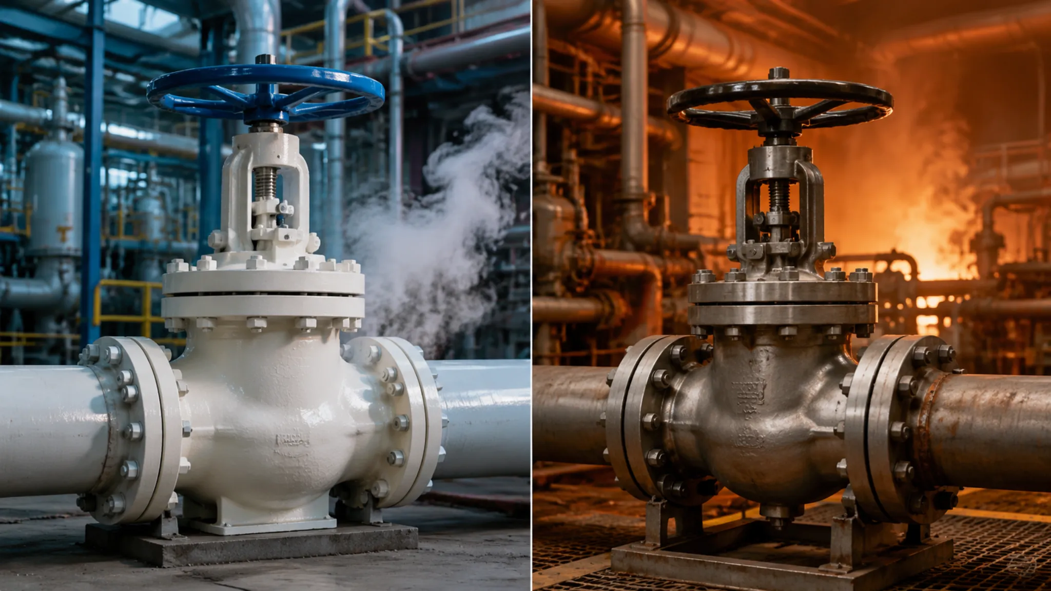
Critically, PTFE near its temperature ceiling (260°C) exhibits significantly reduced creep resistance—long-term pressure exposure causes permanent deformation, increasing the sealing face gap and raising leakage rates. RPTFE, reinforced with 25% carbon fiber, substantially improves creep resistance and maintains higher pressure ratings at equivalent temperatures. PEEK has a melting point of 334°C but its continuous use temperature is limited to approximately 200°C by its oxidative stability. In cryogenic LNG service (-162°C), standard PTFE becomes brittle and loses resilience; PCTFE or specially formulated modified PTFE seats must be selected instead.
Choosing the Best Fit
Seat material selection ultimately requires balancing sealing performance, temperature-pressure tolerance, chemical compatibility, and cost. The following experience-based selection guide covers typical industrial applications:
- For water, air, nitrogen, steam and other conventional industrial media at temperatures ≤200°C and pressures ≤PN40, pure PTFE seats are preferred—their reliable performance and lowest cost make them the default choice.
- For gas streams with minor solid particles (dry natural gas, hot flue gas) or high-temperature steam service (200°C~300°C), RPTFE seats offer the best balance of temperature resistance and wear resistance.
- For high-sand-content applications such as wellhead equipment and oil/gas/water separators, hardened metal seats or tungsten carbide overlaid seats are recommended to resist abrasive wear.
- For strongly corrosive chemicals (concentrated sulfuric acid, hydrofluoric acid, organic solvents), fully PTFE-encapsulated seats are mandatory to completely isolate the sealing face from the corrosive medium.
- For cryogenic media such as LNG, liquid nitrogen, and liquid oxygen, PCTFE or specially modified PTFE seats prevent ordinary PTFE from becoming brittle at low temperatures.
- For high-temperature high-pressure steam systems and hydrogen-containing (sour) service, dedicated engineering evaluation of hydrogen embrittlement tendency and high-temperature creep performance is required.
Final seat selection should be based on the manufacturer’s chemical compatibility chart and P-T rating curves, supplemented by actual operating experience from similar plant equipment. For conditions outside the manufacturer’s standard scope, it is recommended to engage in pre-order technical consultation with the manufacturer, providing detailed medium composition and operating parameters, and obtain written confirmation from the manufacturer.
Selecting the right floating ball valve requires systematic application of fluid mechanics, materials chemistry, and mechanical engineering knowledge. Mastering the Cv value sizing method, media compatibility analysis principles, and seat material performance boundaries described in this article enables engineers to avoid the most common selection errors at the design stage and establish a solid foundation for long-term, trouble-free plant operation.

")