
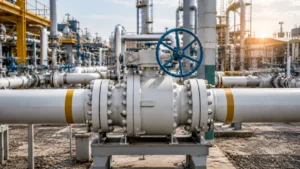
The API 607 certified fire‑safe floating ball valve is specifically designed for fire scenarios, featuring a fire‑resistant construction, anti‑static grounding, and reliable sealing performance, and serves as a key safety barrier for oil and gas pipelines.
Fire Safe Design
How It Seals
Floating ball valves rely on the medium pressure to press the ball against the downstream seat, creating a positive‑feedback seal—the higher the upstream pressure, the tighter the ball contacts the seat and the better the sealing performance.
Under normal operating conditions, PTFE or reinforced graphite (RTFE) seats provide an extremely low leakage rate; the seat seal‑face pressure is automatically maintained by the medium pressure, eliminating the need for additional springs or preload. The graphite ring‑stacked packing (graphite packing set) can withstand temperatures above 300 °C, and even if the soft seal burns it limits leakage through the stem area.
When a fire occurs, the PTFE soft seal begins to soften above 260 °C and carbonizes/fails above 300 °C, but the metal‑to‑metal sealing face (primary metal seal) between the ball and metal seat can still maintain a basic seal without lubrication, preventing large fluid leaks. This metal seal is usually applied as a coating of Stellite or nickel‑based hard alloy on the ball surface, with hardness ≥ HRC 40 and good wear‑ and corrosion‑resistance, making it the key backup seal in high‑temperature fire conditions.
API 607 requires that, after degradation of the soft sealing material, the valve body must keep an external leakage rate ≤ 10⁻³ Pa·m³/s. This criterion is quantified by external‑leakage testing during fire tests, with the test method referencing ISO 15848 sensitivity standards. The valve body must also be equipped with a vent hole; when temperature rise causes the fluid in the central cavity to expand, the pressure is vented to the upstream side, protecting the ball from being blown out. The radial clearance between the ball retention groove and the valve body shoulder must satisfy ASME B16.34 strength verification requirements.
API 607 Tests
The core process of the API 607 fire test consists of five stages, corresponding to the complete technical requirements of API 607 7th edition (2020).
Stage one is heating preparation – the valve under test is mounted horizontally in the test apparatus, a hydrostatic pressure of 1.1 × the rated working pressure is applied (no pressure on the low‑pressure side, simulating a downstream pressure‑loss scenario). After confirming that no visible leakage is present, the valve is ready for ignition. Stage two is the 30‑minute combustion test – a dedicated burner meeting ASTM E207 is used to expose the valve to a flame of 900 °C ± 50 °C. Thermocouples are positioned to cover key locations such as the valve body, bonnet, stem, and connecting piping, and temperature data are recorded every 30 seconds. No operation on the valve is permitted while the flame is applied.
Stage three is post‑cooling seal verification – once the flame is extinguished, the pressure is immediately restored to 1.1 × the rated value. After the valve body temperature falls below 60 °C, a soap‑solution method or ultrasonic testing is used to verify that the external leakage rate satisfies ≤10⁻³ Pa·m³/s. Stage four is the high‑temperature/high‑pressure supplementary test – for certain certification scopes the pressure is maintained within ±5 % of the rated pressure during the combustion test, ensuring that the valve structure does not develop excess leakage or deformation due to material softening at high temperature.
Stage five is cycle‑operation verification – after completing the above tests, the valve must perform at least two full open‑close cycles at ambient temperature and pressure, confirming that the actuator, connectors, and sealing surfaces still function after thermal shock. The opening/closing torque must not exceed 150 % of the initial value recorded during certification. Valves that pass all tests receive an API 607 certificate issued by a third‑party organization such as TÜV, SGS, or DNV. The certificate specifies the covered size range and pressure class and is typically valid for five years.
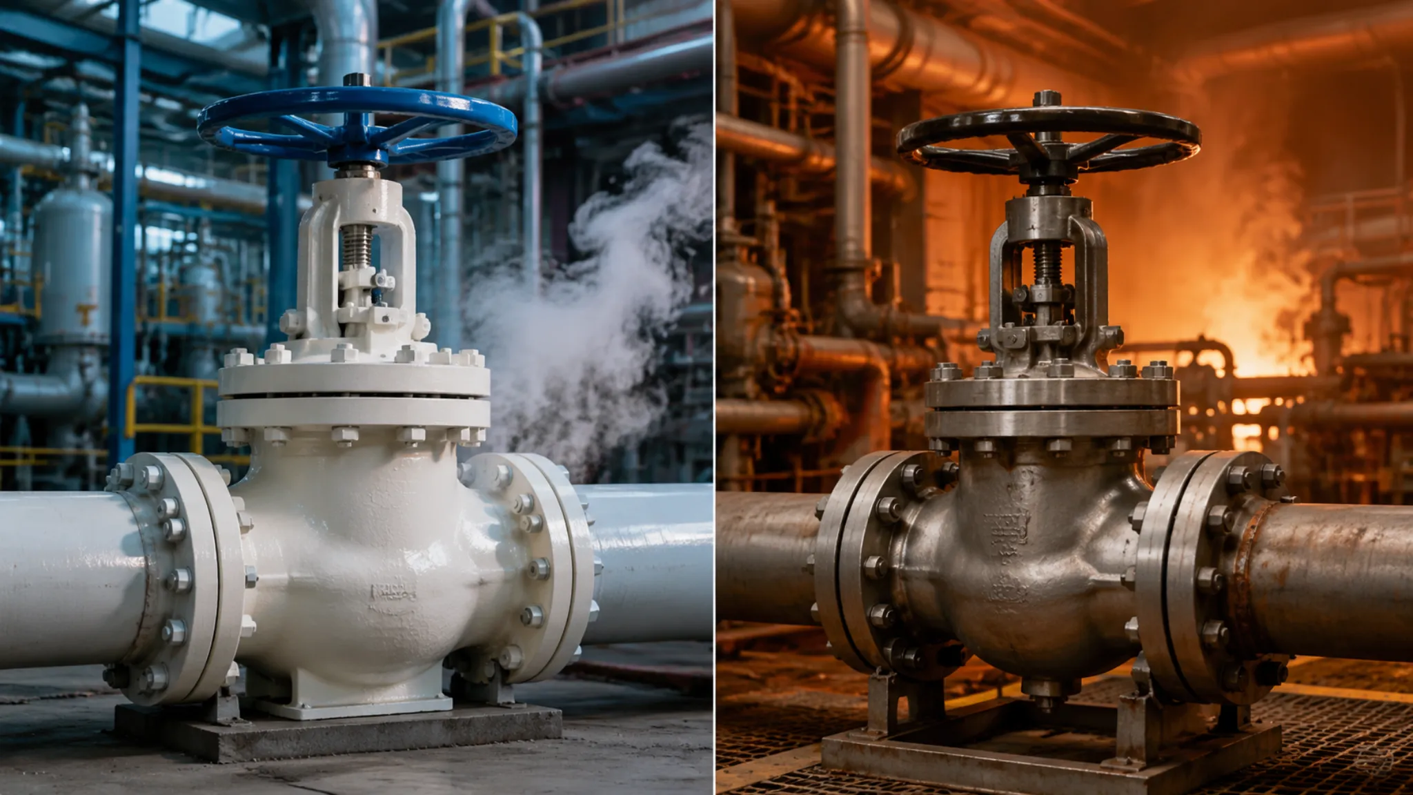
Surviving High Heat
The high‑temperature resistance of fire‑resistant valves is achieved through the coordinated operation of a three‑layer protection mechanism, forming a complete thermal‑protection system from material to structure.
The first layer is the heat‑strength guarantee provided by the valve‑body material. A carbon‑steel valve body can retain about 25 % of its room‑temperature yield strength even under a 900 °C flame, because although carbon steel loses strength at high temperature its toughness is still maintained, preventing immediate brittle fracture. Low‑temperature carbon steel (such as LCC/NL) maintains stable mechanical properties in the range of –46 °C to 345 °C by reducing the upper limits of elements such as Mn and C and increasing Ni content, and is the standard material for API 607 testing. The API 6D specification explicitly requires LCC material to pass a Charpy impact test at –50 °C with an impact energy of 27 J.
The second layer is the failure‑temperature management of the soft sealing material. The standard temperature limit for PTFE is 260 °C (short‑term exposure up to 288 °C); above this temperature it begins to soften, loses resilience, and eventually carbonizes and fails. Reinforced graphite filler (expanded graphite) can withstand sustained temperatures up to 540 °C and is the preferred stem‑packing material for high‑temperature service. Some manufacturers also offer composite graphite packing reinforced with stainless‑steel wire, pushing the oxidation onset temperature (where weight loss begins) above 600 °C.
The third layer is the secondary sealing effect of metal‑to‑metal sealing faces. When the soft seal is completely burned away above 650 °C, the graphite coating or nickel‑based alloy (Stellite) sealing faces between the ball and the seat provide a hard‑seal backup. These two metal sealing faces are designed with sufficient compression margin so that even if the soft‑seal layer disappears entirely, the ball can still maintain a basic seal through self‑alignment. The seventh edition of API 607 (2020) added a cyclic thermal‑shock clause, requiring the valve to complete 10 rapid temperature‑change cycles (from room temperature up to 900 °C and back to room temperature) under a simulated emergency‑closure thermal gradient, further verifying the thermal‑mechanical fatigue life of the sealing structure.
Body Cavity Overpressure Protection
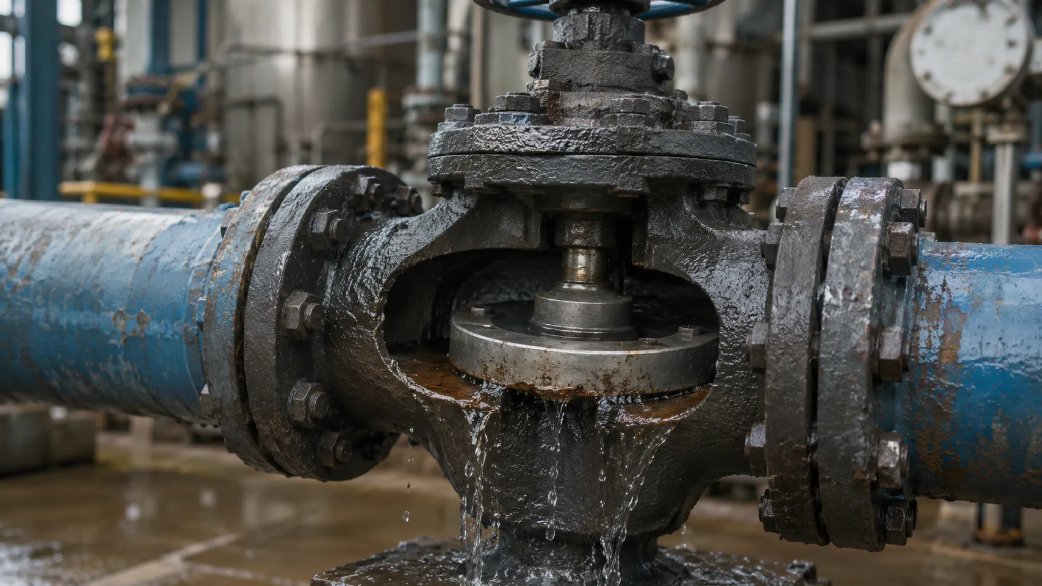
When the pressure in the valve body’s middle cavity abnormally rises, the ball may endure a huge upward thrust, leading to seal failure or even the ball being blown out, which is a major safety hazard for the valve during a fire or abnormal operating conditions. When the temperature rises causing the fluid in the middle cavity to expand, if there is no pressure‑relief path, the middle‑cavity pressure can far exceed the design pressure, causing valve‑cover deformation, seal‑face damage, or ball‑position offset.
API 607‑certified valves are designed with a vent hole on the side of the valve body. When the temperature rise causes the fluid in the middle cavity to expand, the vent hole releases the pressure to the upstream side, protecting the ball from being blown out. This design incorporates ball‑blow‑out protection into the mandatory requirements of API 607 Seventh Edition, and is one of the structural features that distinguish fire‑safe ball valves from ordinary ball valves.
The radial clearance between the ball‑retention groove and the valve‑body shoulder must comply with the strength‑verification requirements of ASME B16.34. Too small a clearance restricts the thermal expansion of the ball, causing operation jamming; too large a clearance increases turbulence of the middle‑cavity fluid, accelerating seal‑face wear. During design selection, the synergistic relationship of temperature, pressure, and clearance must be checked to ensure that throughout the entire design temperature range the ball has sufficient clearance to move without exceeding the allowable leakage limit.
In addition, the size and location of the valve‑body vent hole are strictly regulated. An overly small hole diameter results in insufficient pressure‑relief speed, preventing effective release of middle‑cavity pressure; an overly large hole diameter may affect the overall strength of the valve body. API 607 requires that, at the rated pressure, the vent hole must ensure that the middle‑cavity over‑pressure does not exceed 10 % of the design pressure, which generally corresponds to a hole diameter in the range of 6 mm to 12 mm (for DN 50 to DN 200 valves).
Preventing Static Sparks
Preventing Static Sparks
Why Sparks Form
Static electricity inside a valve is mainly generated by three mechanisms, each of which can produce discharge energy sufficient to ignite common hydrocarbon mixtures.
Flow‑induced charging is the primary cause. When oil, gas, LPG or a chemical medium passes through the valve body at a flow velocity of 2–10 m/s, the double layer at the interface between the medium and the inner wall of the ball and the seat is sheared and separated, causing positive and negative charges to accumulate on the ball and the valve body respectively, forming a floating potential as high as several kilovolts. The ball is typically made of stainless or carbon steel, which has good conductivity, but the PTFE seat is a typical insulator, cutting off the electrical connection between the two sides and preventing the charge on the ball from being discharged to ground through the valve body.
Experimental data show that for a DN50 ball valve at a natural‑gas flow velocity of 5 m/s, the ball potential can reach 3–8 kV, with stored charge about 0.5–2 µC. Ejection discharge occurs when the valve is rapidly opened – high‑pressure medium in the middle cavity, carrying the previously separated charge, jets out at high speed, forming a spark discharge with the metal pipe wall at the outlet, with ignition energy up to 0.5 mJ or more, sufficient to ignite a natural‑gas mixture (minimum ignition energy about 0.25 mJ). Higher flow velocity and greater pressure differential across the valve increase the energy of the ejection discharge.
Human‑body static electricity is the most dangerous in on‑site maintenance scenarios. When maintenance personnel operate the handwheel or packing gland, the 10–30 kV static charge on their bodies is transferred through the valve stem to the charged ball inside, creating an instantaneous discharge spark. Therefore, API 607 valves must incorporate a grounding structure to safely channel static electricity to ground, preventing any form of discharge.
Grounding the Valve
The anti‑static grounding system of the fire‑resistant floating ball valve consists of three parts, which are connected in series or parallel to form a complete grounding path; a break in any part will cause the grounding to fail.
The first part is the direct metal‑to‑metal contact between the valve body and the pipe flanges. When the flanges on both sides of the valve are bolted to the pipe, the contact resistance between the metal surfaces is typically <0.03 Ω (test condition: 50 A current injection). This path is sufficient to direct fault currents to ground when they appear, making it the most reliable permanent grounding path. However, if an insulated gasket such as a PTFE‑coated gasket is used, the conductive path through the flanges is broken, and the system must rely on a dedicated grounding port.
The second part is the dedicated grounding port on the valve body. The standard configuration is an M8×1.25 threaded hole located on the machined surface on the side of the valve body, used with a copper grounding plate (cross‑sectional area ≥4 mm²) and a grounding conductor of at least 6 mm², connecting the valve body to the nearest plant grounding network. The grounding resistance must be ≤10 Ω (measured under dry soil conditions), and in humid environments it should be reduced to ≤5 Ω.
The third part is the cross‑connection between the actuator and the valve body. The metal housing of an electric or pneumatic actuator is connected to the plant grounding network by a separate grounding conductor, forming a redundant parallel path with the valve body’s flange grounding. This ensures that even if the actuator is independently energized (e.g., due to water ingress in the junction box causing leakage), it will not interfere with the ball potential. Some valves certified to API 607 also incorporate an anti‑static stem design, placing a metal spring or conductive packing ring (typically silver‑plated graphite) between the stem and the packing, so that static charge accumulated on the ball is diverted through the stem to the valve cover grounding path, with an equivalent resistance ≤10 Ω. This provides the most direct route for ball‑potential discharge.
Safe Discharge Steps
Valve field grounding operations must be strictly carried out following the steps below; any omitted step may result in grounding failure.
Step 1: Verify that the valve is de‑energized and free of medium pressure. Before opening the actuator junction box, eliminate body static using an explosion‑proof static eliminator, wear an anti‑static wrist strap, and connect the grounding clamp to the plant equipotential grounding grid.
Step 2: Inspect whether the flanges on both sides of the valve body are bolted to the pipeline. For an unconnected, suspended valve the flange surface bears Al₂O₃ and other oxide layers, whose contact resistance can reach hundreds of ohms; it must be grounded individually through a dedicated grounding port.
Step 3: Use a ground‑resistance tester to measure the valve body‑to‑ground resistance. Set the test current to 50 A at 125 Hz; a reading below 10 Ω is acceptable. If a tester is not available on site, a multimeter in low‑resistance mode may be used to check flange‑to‑ground continuity; continuity indicates acceptance (reading < 1 Ω).
Step 4: Check that the actuator housing’s grounding conductor is securely fastened to the metal housing’s grounding terminal (usually marked with a ⏚ symbol). It is prohibited to wind the grounding conductor around a bolt without using the dedicated terminal.
Step 5: Repeat the above measurements annually before the rainy season and after major overhauls. If corrosion causes the grounding resistance to exceed the limit, immediately grind the coating and re‑tighten the grounding plate.
After completing these steps, the valve is in a safe grounded state, and the risk of electrostatic discharge is reduced to an acceptable level.
Anti-Static Stem Design
Anti‑static valve stem design is the only component that can still maintain a grounding function after the soft seal is completely burned out, playing an irreplaceable role in protecting maintenance personnel during a fire.
In a fire scenario, after the graphite packing gland carbonizes and fails at high temperature, the metal spring or conductive packing ring between the stem and the packing remains in physical contact, ensuring that the static‑discharge path stays intact. Even in the worst case where the packing gland is completely burned through, the metallic elasticity of the spring can still preserve the conductive connection between the stem and the packing, preventing the risk of static sparks when maintenance staff operate the handwheel or packing gland after the fire.
Testing has shown that the grounding resistance from the stem to the bonnet remains ≤ 10 Ω after the packing is burned out. Some manufacturers provide test reports of the resistance under packing‑burnout conditions as a design‑verification basis, and users should request these reports during valve selection.
When selecting a valve, attention should also be paid to the stem material. There is a risk of galvanic corrosion between a stainless‑steel stem and a carbon‑steel body, which can increase the contact resistance over long‑term operation. It is preferable to choose a stem material that matches the body material or is close in the galvanic series. Some high‑end valves use nickel‑based alloy stems to simultaneously achieve high‑temperature strength and galvanic compatibility. The anti‑static stem’s grounding function must undergo a special factory test—simulate a high‑temperature failure of the packing area, then measure the equivalent resistance from the stem to the bonnet, confirming that it remains ≤ 10 Ω.
During acceptance, the user should require the manufacturer to provide this special test report as direct evidence of the effectiveness of the anti‑static stem design.
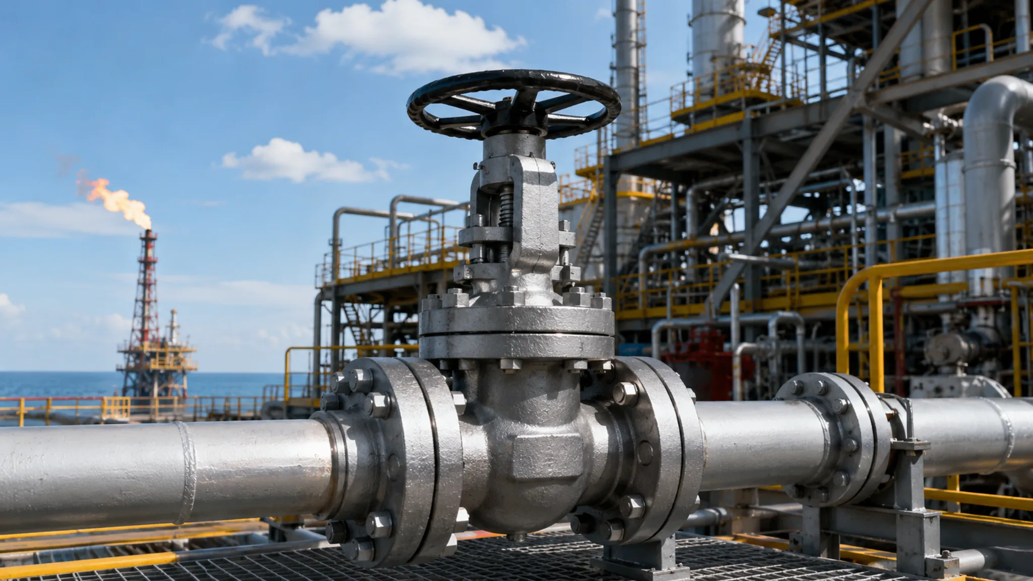
Oil and Gas Uses
Oil and Gas Uses
Pipeline Safety Needs
The reliability requirements for fire‑protection valves in the oil and gas industry stem from three severe service conditions; failure in any one can lead to catastrophic consequences. In high‑pressure transmission, long‑distance pipelines typically operate at 6–10 MPa (Class 600–Class 900), and the pressure differential across compressor stations can reach 15 MPa. Valves under such high differential pressure endure continuous fluid excitation and thermal cyclic fatigue. Take a Class 600 DN200 ball valve as an example: the rated torque is about 800 N·m, but during high‑differential shut‑off the peak torque can reach two to three times the rated value (1,600–2,400 N·m). When selecting an actuator, an adequate margin must be provided based on this multiplier. Regarding flammable media, natural gas consists mainly of methane (in LNG cases it includes liquefied methane at –162 °C). Its minimum ignition energy is only 0.25 mJ, and its lower explosion limit (LEL) at 25 °C is 5 %, indicating extremely high fire risk. The fire‑protection design of the valve must maintain sealing capability for at least 30 minutes under fire temperatures of 900 °C, to prevent large‑scale leakage of upstream high‑pressure gas into the fire zone and thereby aggravate the fire. In terms of corrosion and sulfides, acid natural gas containing H₂S accelerates stress corrosion cracking (SCC) of valve materials. If an API 607 valve is used in an acidic service, the valve body material must comply with NACE MR0175 or ISO 15156; when the H₂S partial pressure exceeds 0.0034 kPa, carbon‑steel bodies are prohibited and the material must be upgraded to austenitic stainless steel or a nickel‑based alloy. The seat and packing must be selected from hard alloys (e.g., Stellite) or special coatings that are compatible with the acidic medium. For offshore platform fire‑protection systems, fire‑protection valves also have additional weight limits and salt‑spray test requirements (ASTM B117, 1000 h). Products must be selected from series certified by DNV‑GL, ABS, or BV, and the valve housing surface must be treated with hot‑zinc spray or epoxy coating.
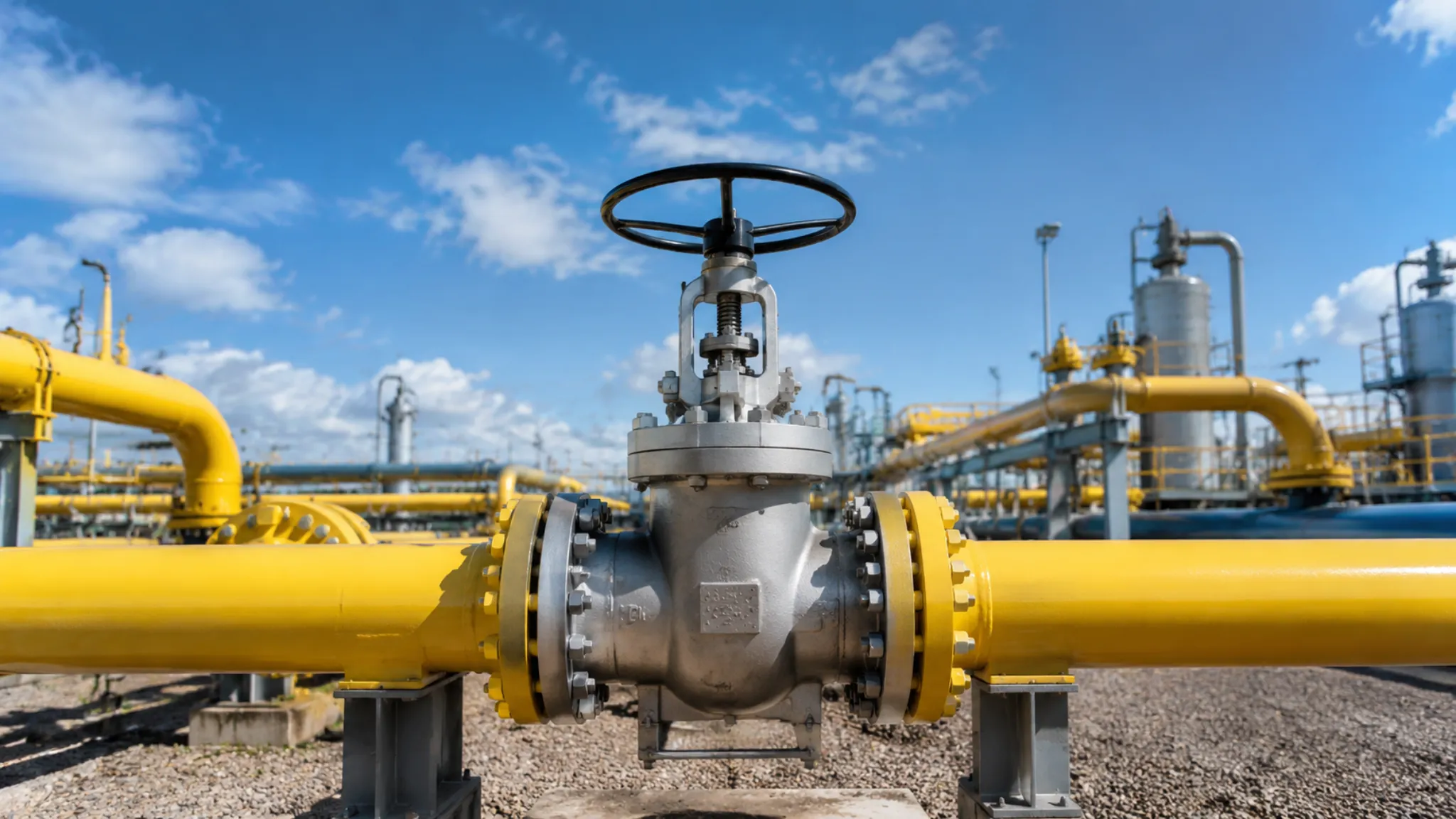
Choosing Right Sizes
The size selection of pipeline ball valves involves cross‑matching three dimensions—bore (nominal size), pressure rating, and connection type. A mismatch in any one can cause a cascade of failures such as vibration, erosion, and seal leakage.
In terms of bore matching, a full‑bore ball valve (bore ≈ ID) has the same inner diameter as the pipe, giving the highest Cv (almost no pressure drop) and minimal flow resistance. This makes it suitable for mainlines that must accommodate pipeline‑pigs, such as oil‑ and gas‑transmission lines or refinery feed lines. A reduced‑bore ball valve (bore = NPS‑1 or NPS‑2, i.e., one or two pipe sizes smaller than the pipeline) is more economical for bypass lines, metering circuits, and upstream of control valves, but it causes a significant increase in pressure drop. For example, a DN100 pipeline with a DN80 reduced‑bore valve results in a Cv reduction of about 35 %; throttling generates cavitation that accelerates seat erosion, and the noise level rises roughly 15 dB for each 1 bar pressure drop.
Regarding pressure rating, ball valves of the same bore can be offered in several pressure classes—Class 150/300/600/900/1500/2500. Selection is based on the pipeline design pressure with a 25 % safety margin. For instance, a pipeline with a design pressure of 8 MPa should be specified as Class 600 (rated 10 MPa) rather than Class 300 (rated 5 MPa); otherwise the valve body wall‑thickness margin is insufficient, making it prone to stress‑corrosion fatigue. An excessively high pressure rating is also undesirable; a Class 1500 valve has a wall thickness about three times that of a Class 600, leading to substantially increased weight and cost.
In terms of connection type, flanged connections (RF flat face or RTJ ring‑joint face) are the most common, covering pressure ratings from PN20 to PN420 and facilitating on‑site removal, replacement, and maintenance. Butt‑weld ends (BW) are more compact for medium‑size pipelines, providing zero external leakage, but if a leak occurs they cannot be repaired online. Socket‑weld (SW) connections are suitable for small‑bore high‑pressure valves below 2 NPS (e.g., instrument root valves), offering greater pressure‑bearing capacity than flanged joints and a shorter leakage path.
Carilo Valve’s product line covers full‑bore and reduced‑bore sizes from DN15 to DN300, pressure ratings from PN20 to PN420 (Class 150 to Class 2500), and connection options including flanged, butt‑weld, and socket‑weld, thereby satisfying the selection requirements of the vast majority of oil‑ and gas‑processing facilities.
Main Selection Tips
Correct selection of fire‑safe floating ball valves can greatly reduce the total life‑cycle cost of pipeline operation. The following six steps constitute the core framework for selection.
**Step 1 – Confirm the medium parameters.** Identify operating pressure, operating temperature, the presence of corrosive species such as H₂S or CO₂, and the medium’s viscosity and density. These data dictate material and seal‑ring choices.
**Step 2 – Determine the pressure class.** Choose the appropriate Class rating from the ASME B16.34 pressure‑rating table, and verify that the pressure‑temperature (P‑T) curve covers the design temperature. For high‑temperature service at Class 600 or above, special attention must be paid to the de‑rating factor.
**Step 3 – Verify fire‑test certification.** Ensure the valve carries a valid API 607 certificate and that the bore/pressure range listed on the certificate matches the selected size (API 607 permits a DN range up to twice the size, e.g., a 4‑NPS valve can cover 4 to 8‑NPS).
**Step 4 – Validate anti‑static design.** Confirm that the valve body has grounding ports, the stem provides a conductive path (anti‑static stem) or an equivalent grounding arrangement. In ATEX/IECEx explosion‑proof zones, compliance with IEC 60079‑0 for static‑ignition protection is also required.
**Step 5 – Match the connection type.** Select flange, butt‑weld, or socket‑weld connections according to the pipeline design; the flange face type (RF/RTJ) and the gasket rating must be compatible with the pipeline.
**Step 6 – Confirm the actuator type.** Whether manual gearbox, pneumatic actuator, or electric actuator, the unit must provide the correct output torque and cycle‑count data. For pneumatic actuators, the operating pressure range (typically 0.4 – 0.7 MPa) must also be specified.
Completing these six steps ensures that the valve will operate safely and reliably throughout the entire design life of the pipeline.
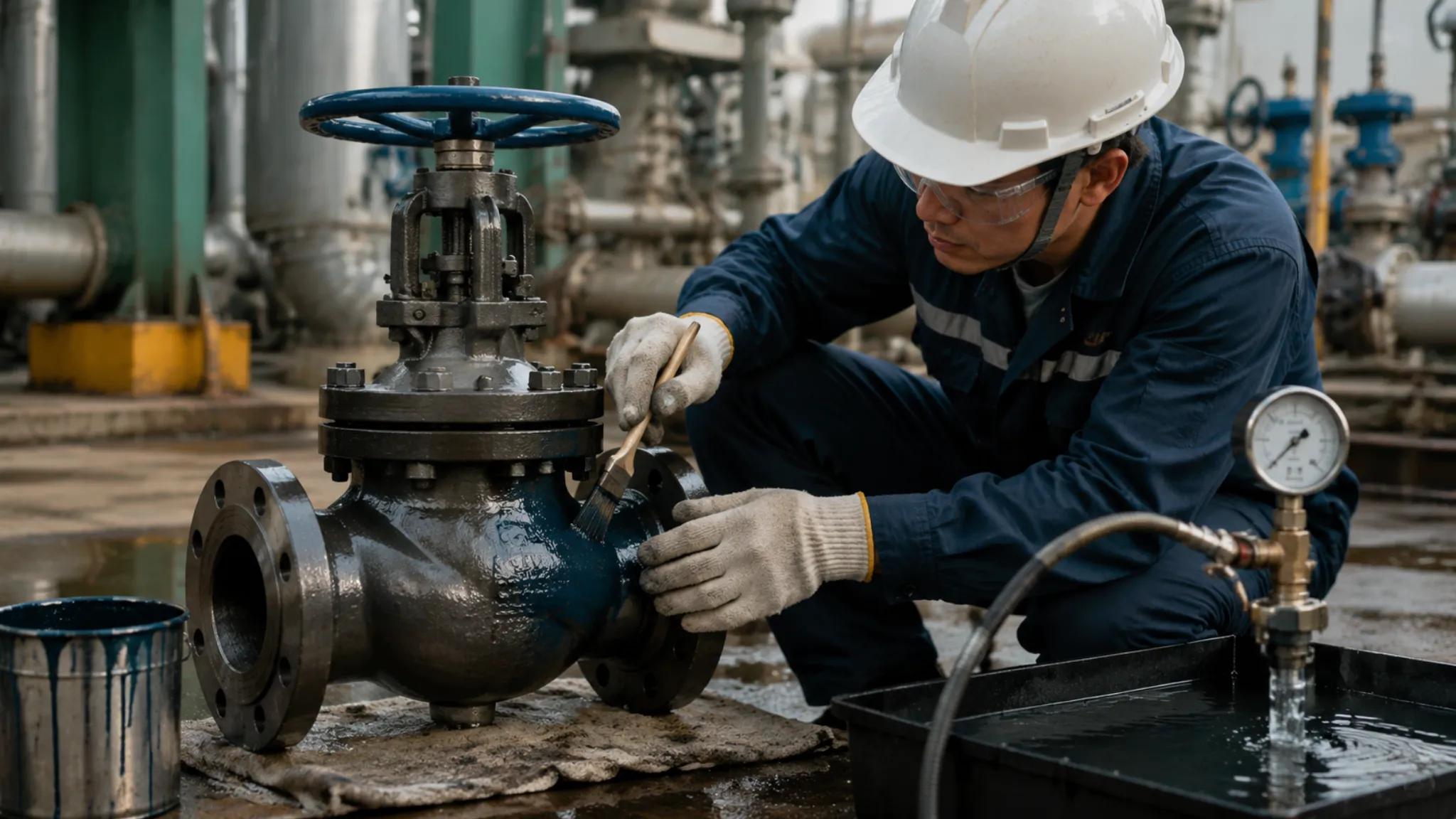
Maintenance and Inspection
Fire-safe floating ball valves require regular maintenance and inspection throughout the entire lifecycle of the pipeline to ensure that fire sealing and antistatic performance remain reliably maintained.
For startup and shutdown inspections, the stem-to-ball assembly should be checked during each planned shutdown—verify that the stop screw or key connection is secure to prevent loosening during thermal cycling; check that the packing gland cap torque is within the 30~50 N·m range; confirm that the fire-safe sealing materials show no visible damage, cracks, or corrosion; and ensure that the valve body pressure relief hole is clear and free of obstructions. The integrity of the stem-to-ball assembly also affects antistatic performance—if the stop screw becomes loose, the electrical connection between the stem and ball may be interrupted, causing the antistatic stem design to fail.
For periodic test intervals, these are determined based on pressure class and service conditions—Class 150~300 valves are tested once every 24 months, while Class 600 and above are tested once every 12 months. Test contents include: flange bolt connection verification (tightened symmetrically using the cross-pattern method); actuator connection inspection (secure, no looseness, no corrosion); fire-safe sealing materials condition inspection; and pressure testing (1.1 times the rated working pressure, using soap solution method for external leak detection). Valves that have been emergency-activated must be inspected within 72 hours, and emergency operation records must include trigger conditions and operation duration.
Carilo Valve provides material certificates, test reports, and operation manuals for each valve, ensuring users can complete full-process maintenance according to specifications. Completing the above inspections and tests ensures that fire-safe floating ball valves operate safely and reliably throughout the entire lifecycle of the pipeline.
Carilo Valve (Zhejiang Carilo Valve Co., Ltd.) specializes in the research and manufacture of fire-safe floating ball valves, with the entire product line certified to API 607 Seventh Edition. Valve body materials include carbon steel, stainless steel, duplex steel, and cryogenic alloy steel, with grounding resistance ≤10Ω, meeting the stringent requirements of high-risk industries such as oil and gas, petrochemical, offshore, and LNG sectors.

")