
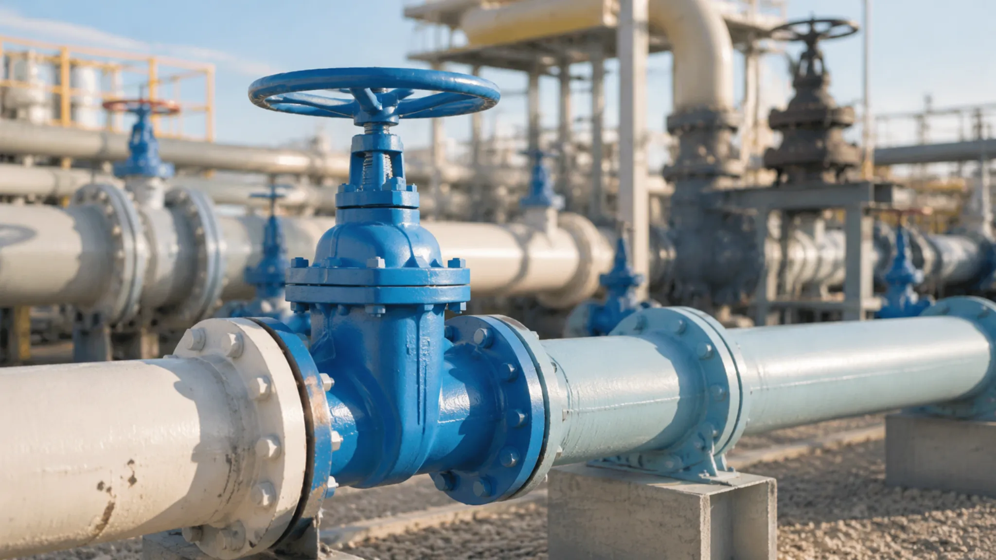
Soft seated floating ball valve sealing reliability directly determines process safety. My records from a petrochemical project show: rated seal life of 50,000 cycles, reduced to 8,000 cycles with contamination, with leaks occurring on average 18 months after startup.

Soft Seat Wear
High Pressure Damage
When soft seat sealing faces endure stress far exceeding design thresholds under high-pressure conditions, the sealing material undergoes plastic deformation or even microscopic crack propagation. API 598 requires soft seated floating ball valves to hold 1.1x rated pressure for 5 minutes with no visible leakage. However, actual high-pressure impact loads often exceed static test conditions, causing seal face damage under sustained high differential pressure.
| Pressure Class | Seal Face Stress Characteristics | Primary Damage Mode |
| 150-300LB | ≤6.9 MPa uniform stress | Seal ring uniform compression deformation, recoverable |
| 600LB | 6.9-10.3 MPa stress concentration | Local micro-cracks at seal lip root |
| 900-1500LB | 10.3-25.8 MPa impact load | Seal material extrusion, permanent seal lip collapse |
| 2500LB | ≥25.8 MPa extreme impact | Seal face cracking, immediate replacement required |
The direct consequence of high-pressure damage is decreased sealing specific pressure. In CARILO forged soft seated floating ball valves, the floating ball design uses medium pressure for self-sealing—higher pressure creates greater sealing force. But this mechanism requires an intact seal face; once plastic deformation has occurred, added pressure accelerates seal material extrusion rather than improving sealing, intensifying leakage. During an actual overhaul, I encountered a DN50/600LB valve that lost all sealing during an overpressure test. Disassembly revealed the seal ring compressed from 3.2 mm to 1.8 mm, with the lip area showing no rebound capability whatsoever.
Friction Over Time
Every switching cycle produces friction between the floating ball and soft seat sealing face. CARILO soft seated floating ball valves are rated for 10,000 cycles (ISO 5208 test conditions), but actual field friction far exceeds standard test conditions. Friction damage operates through three primary mechanisms: abrasive wear, adhesive wear, and surface fatigue.
Abrasive wear is the dominant failure mode. When process fluid carries solid particles harder than the seal material (typically PTFE or reinforced PTFE with Durometer hardness approximately D60-65), each cycle acts as micro-grinding on the seal face. PTFE’s microstructure under microscopy reveals a porous surface; microscopic hard particles embedded in the seal face form a three-body abrasion system with grinding efficiency an order of magnitude higher than simple two-body friction. During an overhaul at a refinery atmospheric distillation unit, I disassembled a DN80/300LB soft seated ball valve that had operated continuously for 3 years. The seal face showed visible groove patterns up to 0.15 mm deep, with groove direction matching the ball’s rotation trajectory during switching—a characteristic abrasive wear signature.
Adhesive wear occurs at microscopic contact regions on the seal face. Under combined high pressure and temperature, PTFE materials develop slight adhesive transfer—a phenomenon where PTFE molecules attach to the metal ball surface during friction heating. Non-uniform transfer film causes non-uniform shear during subsequent friction, forming surface spalling. Thermal fatigue results from accumulated friction heat blurring the seal material’s thermal decomposition boundary; under repeated thermal stress, micro-cracks form deep in the seal face and propagate along grain boundaries, ultimately manifesting as seal face spalling. These three wear mechanisms typically operate simultaneously in the same valve, differing only in which predominates.
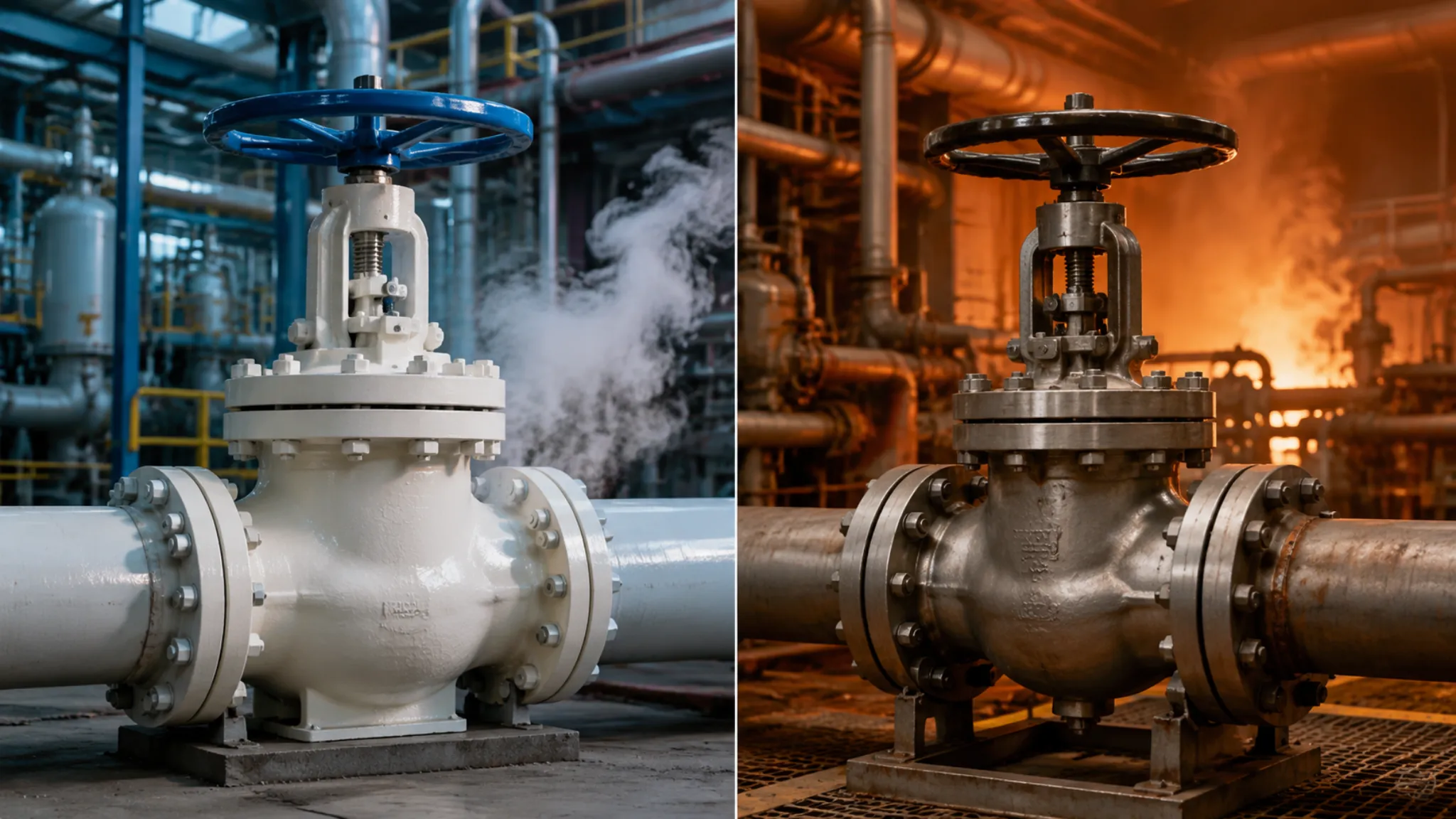
High Heat Limits
Soft seated valve temperature limits are governed by sealing material thermal stability—exceeding the upper temperature limit causes mechanical property degradation or thermal decomposition. CARILO soft seated ball valves standard configuration uses PTFE sealing with a temperature limit of 232°C (450°F); high-temperature options include PCTFE (up to 260°C) or PEEK (up to 300°C). Exceeding material limits causes these specific damages:
- PTFE seals above 260°C experience pronounced thermal decomposition, releasing toxic fluorinated gases with complete loss of sealing elasticity
- CTFE or PCTFE above 200°C exhibits cold flow phenomenon with continuously decreasing seal ring thickness
- PEEK seals above 300°C begin glass transition with approximately 40% reduction in mechanical strength
- All soft seat materials under thermal cycling conditions develop thermal stress concentration cracks at the seal lip
Temperature damage is characterized by latency—over-temperature may produce no visible leakage immediately, yet the seal material’s molecular weight has already undergone irreversible decrease. After 3-5 over-temperature cycles, sealing performance typically degrades to below 50% of design values. This means a valve maintaining sealing shortly after over-temperature exposure cannot be used as evidence of continued serviceability. During maintenance on an ethylene plant quench system valve, temperature records showed the seal area operating 38°C above nameplate rating with cumulative over-temperature exposure of approximately 120 hours—enough to justify including the entire valve batch in the maintenance overhaul plan.
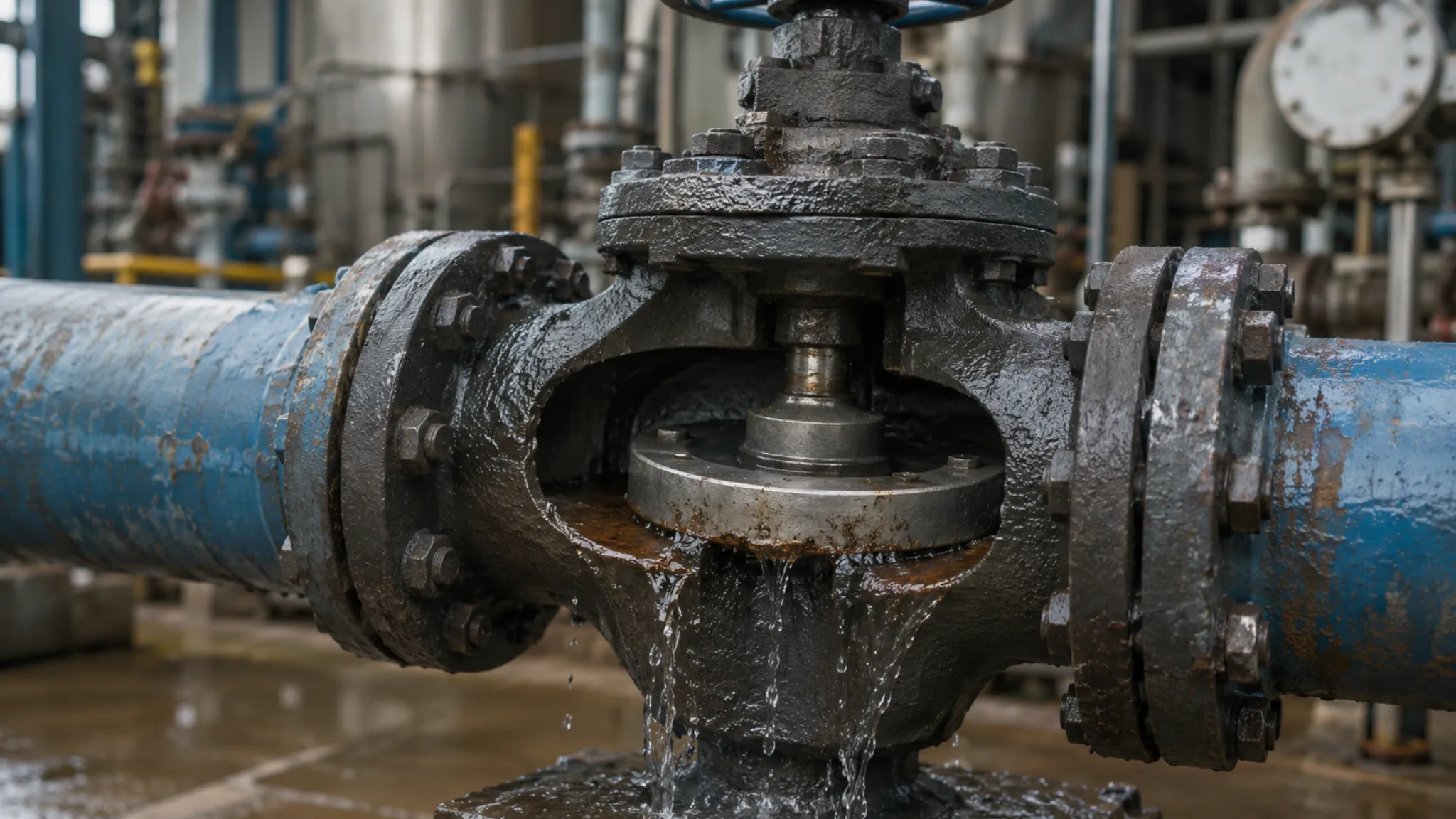
Damage From Debris
Dirt In Fluid
The most common cause of soft seated valve seal failure is solid particle contamination in the process medium infiltrating the seal area. Unlike metal seated valves, soft seated sealing contact stress distributes across a wider annular region, making PTFE and similar soft materials extremely sensitive to foreign particle embedment. Particle intrusion follows three main paths: installation residue, construction contamination, and inherent process medium particles.
Installation residue is the most preventable yet most frequently overlooked contamination source. During field installation, welding slag, grinding dust, and flange face protective compound residue (rust preventive oils, greases) can all adhere to the seal face. While CARILO performs nitrogen purging and visual inspection of valve internals before shipment, contamination control during field installation depends entirely on construction quality. During commissioning at an LNG terminal, six DN50 soft seated ball valves experienced sequential internal leakage within 3 days of startup. Disassembly revealed yellow rust wax residue on all seal faces—applied on-site to protect flange faces during installation but never properly removed beforehand.
Inherent process medium particles are a far less controllable contamination source. In oil and gas extraction, slurry transport, and coal chemical operations, media inherently contain solid phases (sand, catalyst fines, coal ash); these particles get driven into the seal area under fluid pressure. Particle intrusion simultaneously triggers three damage mechanisms: seal face scratching (direct mechanical damage), altered sealing specific pressure ratio (particles elevate the seal face off its seat), and abrasive wear (continuous grinding). Particles above 200 mesh (74 μm) typically produce visible scratches on PTFE seal faces, and actual field particle size distributions are usually considerably wider.
Scratched Seat Surface
Seal face scratches are direct evidence of particle damage and the most visible failure mode in soft seated valve leakage. Scratch severity determines whether the valve can be repaired through grinding or requires seat replacement. Scratch morphology characteristics—direction, depth, distribution—help identify particle source and entry path, providing critical guidance for developing maintenance strategy.
| Scratch Characteristic | Particle Source Inferred | Damage Severity | Recommended Action |
| Uniform shallow circular scratches (<0.05mm) | Installation residue (primarily SiO2) | Mild — grinding repair possible | Hand grind with 600-grit sandpaper |
| Unidirectional deep grooves (0.1-0.3mm) | Construction contamination (weld slag) | Moderate — professional grinding needed | Professional grinding service, verify sealing |
| Irregular star cracks | Hard catalyst particles (Al2O3) | Severe — seat replacement required | Replace soft seat assembly |
| Large-area indentation (>30% seal area) | Large particles long-term embedded (>500μm) | Critical — entire valve replacement | Replace valve and add filtration |
Determining whether seal face scratches are repairable has a simple field standard: draw a fingernail across the scratch. If the nail passes unobstructed, depth is under 0.1 mm (grinding feasible); if the nail catches noticeably, depth has reached 0.15 mm or above (seat replacement required). This method does not apply to hard-faced alloy-coated seals. For CARILO reinforced PTFE seats, the recommended grinding depth limit is 0.15 mm, with post-grinding surface roughness required at Ra 0.8 μm or better to maintain sealing performance.
Trapped Solid Parts
When solid particles embed in the seal face and are not promptly removed, they form a rigid bed between the floating ball and seat, producing more complex damage under subsequent compression and shear during operation. Trapped solid particles are far more damaging than simple scratches because they alter the structural stress state of the sealing assembly.
- Particles embedded deeper than 0.2 mm create localized stress concentrations at the seal face when the floating ball closes, with stress peaks reaching 3-5 times average sealing stress—directly causing seal face fracture
- Particles pushed during cycling carve arc-shaped trajectories on the seal face; these arc scratches typically point toward the valve’s flow direction, helping identify particle entry direction
- Hard particles (hardness >800 HV, such as silicon carbide and alumina) embed into the soft seal material under ball closure while simultaneously leaving corresponding indentation marks on the opposite metal ball surface, causing ball damage
- Soft particles (graphite powder, coke fines) form flexible beds in the seal area; while not directly puncturing the seal face, they alter sealing pressure distribution, creating local leakage paths
- Severe particle accumulation prevents the floating ball from fully seating, leaving it tilted 3-5 degrees after closure so one side of the seal lip bears the entire sealing load—causing rapid wear
During maintenance on high-pressure separator inlet and outlet ball valves at a coal direct liquefaction facility, I encountered a typical case: eight DN50/900LB soft seated ball valves experienced sequential internal leakage 6 months after startup. Disassembly revealed 1-3 coal ash sintering particles embedded in each valve’s seal face, with particle sizes of approximately 0.8-1.2 mm in irregular shapes. These particles had partially sintered under high temperature and pressure conditions, forming metallurgical bonds with the seal face that grinding could not remove—seat replacement was the only option. This case demonstrates that online strainer configuration is essential for protecting soft seated valves in coal chemical service.
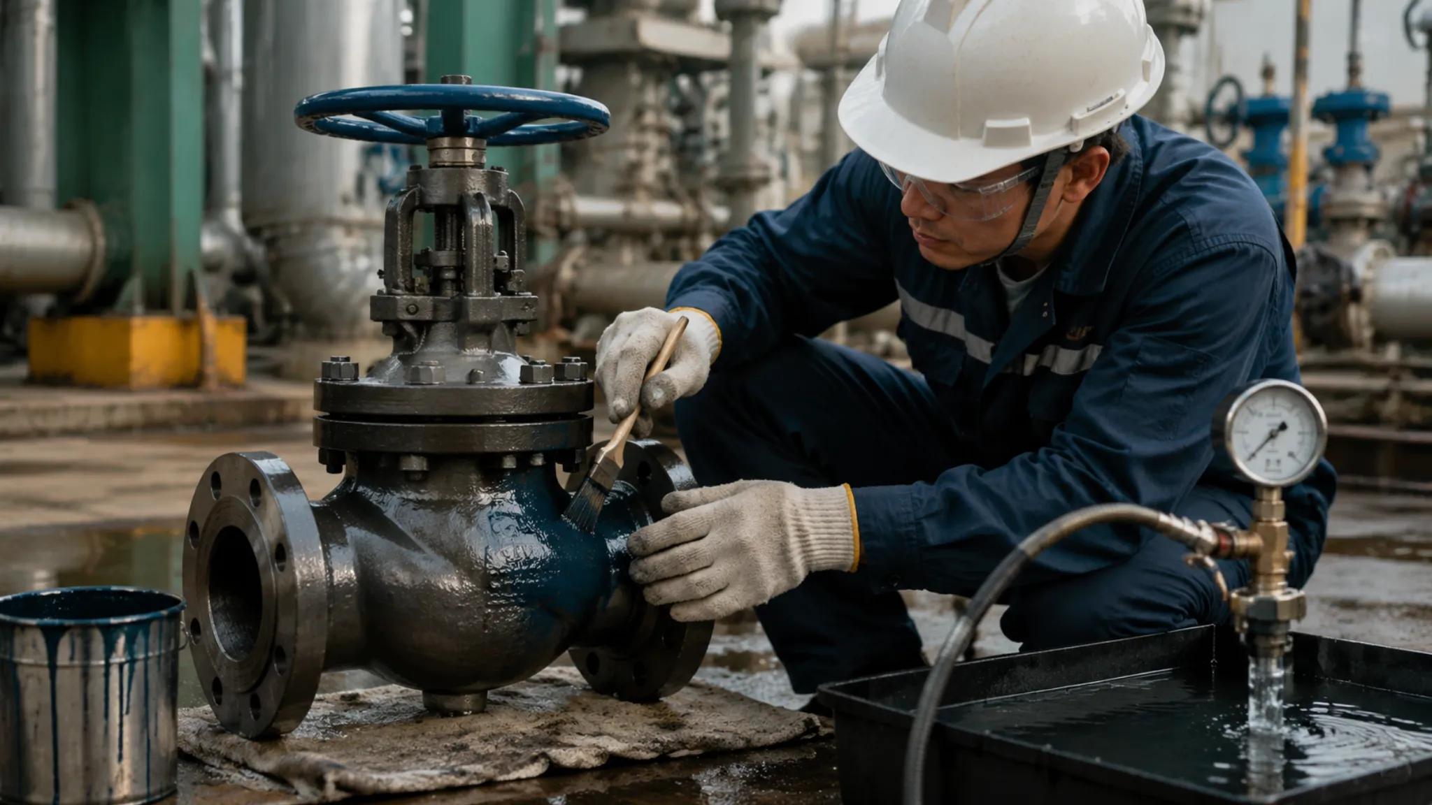
How to Fix
Cleaning Internal Parts
When valve internal leakage occurs, cleaning internal components is the first step to restoring sealing performance and assessing damage severity for developing subsequent action plans. The cleaning process must be systematic—residual particles during reassembly will re-damage the seal face. Here is the validated standard cleaning procedure:
- Document initial condition: Before disassembly, record valve switching position, flow direction markings, and leakage phenomena (internal/external/seepage). Photograph initial seal face condition if possible.
- Isolate and depressurize: Close upstream and downstream valves, empty valve cavity pressure, purge with nitrogen 3 or more times, confirm cavity pressure is zero before disassembly.
- Remove valve cover: Loosen body bolts symmetrically (never fully remove one side first). Inspect cover gasket condition and record gasket compression.
- Extract floating ball: Use a dedicated ball extraction tool (avoid scratching the ball surface). Remove floating ball from valve cavity and inspect for scratches, indentation marks, or corrosion.
- Inspect seats: Remove upstream and downstream seats with plastic tweezers. Check seal lip integrity and measure seal ring free-state cross-section diameter (compare to original dimensions to assess compression).
- Ultrasonic cleaning: Place seats and floating ball in acetone or dedicated valve component cleaning solution. Ultrasonically clean for 15-20 minutes at no more than 60°C.
- Visual inspection and reassembly: Inspect seal face with 30x magnifier to confirm no residual scratches or embedded particles. Reassemble in reverse disassembly order. Apply CARILO standard torque values.
Important note: During steps 4 and 5, floating ball and seats removed from the cavity should be immediately wrapped in clean non-woven fabric to avoid long-term airborne dust adsorption. Cleaned components should be placed with seal face oriented upward before reassembly to prevent particle re-deposition.
Replacing Soft Seats
When seal face damage exceeds grinding repair limits, soft seat replacement is mandatory. Seat replacement involves valve disassembly and requires professional judgment. This decision matrix evaluates seal damage extent, operating conditions, and maintenance costs across three dimensions to help determine whether to replace the seat or the entire valve:
| Evaluation Dimension | Replace Seat | Replace Entire Valve |
| Seal face damage state | Visible scratches but depth <0.3mm, area <20%; seat body crack-free | Seal face fractured, chipped, or embedded particles irremovable; seat deformed or cracked |
| Operating time | New valve in service <3 years or <5,000 cycles; seat not yet at design fatigue limit | Valve in service >5 years or >8,000 cycles; seat comprehensive performance significantly degraded |
| Service medium | Clean medium (no solid particles, particle size <50μm), temperature and pressure within nameplate ratings | Solid particle medium (catalyst, slurry, sandy oil/gas), or frequent over-temperature/over-pressure |
| Maintenance window | Planned maintenance (non-emergency shutdown) with sufficient time for professional reassembly and sealing verification | Emergency repair requiring rapid restoration; no conditions for precision grinding |
| Total cost | Seat spare parts low cost (approximately 15-25% of total valve price) and valve installation space permits disassembly | Replaced seat has limited expected life—direct new valve replacement offers better value |
CARILO provides original-configuration soft seat assemblies (seat insert assembly) including seat ring, O-ring, and gasket, divided into different specifications by pressure class and size. During replacement, seat orientation must be correct—the side with sealing lip typically faces the high-pressure upstream side. Incorrect orientation prevents sealing entirely. After replacement, API 598 seal performance verification is mandatory before returning the valve to service.
Regular Valve Checks
The most effective means of preventing soft seated valve leakage is establishing a systematic regular inspection mechanism that identifies and addresses seal degradation before it progresses to the leakage stage. Drawing on industrial valve maintenance standards (API 570 / ISO 15848) and field experience, a three-level inspection system is recommended:
- Daily inspection (weekly/monthly): Record valve operating status (cycle count, run time, abnormal noise); use infrared thermometer to detect valve body surface temperature—a local temperature rise exceeding 15°C above ambient at the seal area signals potential sealing issues; check stem packing area for visible leakage.
- Periodic inspection (every 6-12 months or every 10,000 cycles): Compare valve operating records to assess whether cycle frequency approaches design limits; use ultrasonic testing (UT) to quantify seal performance degradation through leakage ultrasonic signal intensity; check external valve corrosion—coating peeling exceeding 20% of surface area requires repainting.
- Disassembly inspection (every 3-5 years or when anomalies occur): During planned shutdowns, perform disassembly sampling inspection on critical soft seated valves, with sampling ratio recommended at 10-15% of total critical valves; measure seal ring cross-section diameter to determine compression permanent set (normally should not exceed 15% of original dimensions); measure floating ball surface roughness—values exceeding Ra 0.8 μm require grinding repair.
Establishing valve health files (valve history file) forms the data foundation for predictive maintenance. Each important valve should record: installation date, cumulative cycle count, maintenance history, seal performance test data, and current condition rating (A/B/C/D four-tier, A being optimal). When condition rating drops from B to C, maintenance or replacement planning should begin—avoiding continued operation at C-level until leakage failure occurs. I participated in building a valve asset management system (vAMS) at a petrochemical plant; integrating valve condition data into the DCS enabled online monitoring of over 200 critical valves, reducing unplanned shutdowns from an annual average of 12 to just 3.
Remember three critical thresholds: scratch depth of 0.15 mm marks the repair upper limit; PTFE seat compression permanent set of 15% signals replacement necessity; particle size of 200 mesh (74 μm) is the visibility threshold for scratches. Know these numbers and maintain your valves with confidence.

")