
API 6D is the governing standard for pipeline ball valve design. I once reviewed a natural gas city gate station where an engineer cited Class 300 at 2.0 MPa (38°C), overlooking a 260°C design temperature — the resulting 3.8 MPa gap is enough to cause a serious valve selection error.
Core Design Specs
Pressure Ratings
ASME B16.34 establishes pressure-temperature relationships where the same pressure class yields different pressure ratings at different temperatures — the most frequently misapplied principle in valve sizing. I once compiled a pressure class reference table during a technical review: Class 150 at 260°C is rated 1.0 MPa; Class 300 is 2.0 MPa at 260°C but rises to 5.0 MPa at 454°C; Class 600 at 260°C reaches 10.0 MPa; Class 900 at 260°C reaches 15.4 MPa; Class 1500 reaches 26.0 MPa for high-pressure water injection wellheads; Class 2500 reaches 42.0 MPa but is available as standard batch only for NPS 2–NPS 12, with larger sizes requiring custom fabrication and 12–18 month lead times. The same pressure class designation at different temperatures can represent pressures that differ by a factor of several times — this is the most error-prone detail in sizing documentation.
Valve body wall thickness grows non-linearly with pressure class. The same DN400 bore, Class 300 wall thickness is approximately 24 mm; Class 600 increases to approximately 36 mm; Class 900 further to approximately 48 mm. Wall thickness increases affect not only body weight — Class 600 DN400 trunnion valve body weighs approximately 2.4 tonnes — but also flange dimensions and pipe branch design. I once wrote Class 300 when Class 600 was required for a Southeast Asian seawater desalination project, causing all companion flange specifications to be wrong and delaying the rework cycle by 3 weeks.
ASME B16.34 rated pressures are calculated using the allowable stress method, where material yield strength decreases at elevated temperatures, meaning the Maximum Allowable Working Pressure (MAWP) for the same class varies with design temperature. Taking a Class 600 DN100 ball valve as an example: MAWP at 38°C is approximately 13.8 MPa, but at 260°C the same valve’s MAWP drops to 10.0 MPa — a 3.8 MPa gap. If an engineer references the 38°C value for a high-temperature pipeline application, the valve body will be subjected to internal pressure exceeding its rating during operation, creating a serious safety hazard. During a PTA plant high-pressure steam pipeline design review, I found the design temperature was 300°C yet the engineer had cited the ASME B16.34 value at 260°C — the recalculation showed Class 600 valves had insufficient safety margin at this temperature, and Class 900 was required, adding approximately $180,000 to procurement costs but eliminating the overpressure risk.
- Class 900 body is approximately 35–40% heavier than Class 600 due to thicker walls, larger stem, and upgraded bolting — cost differences are non-linear
- NPS 24 Class 300 flange OD is approximately 1.5 m; large-bore valves require dedicated lifting plans budgeted during project execution
- High-pressure valve selection must confirm end connection type (RF/RTJ/BW) simultaneously — otherwise flange procurement specs will not match the valve body
| Pressure Class | Rated Pressure at 260°C | Rated Pressure at 454°C | Typical Application |
|---|---|---|---|
| Class 150 | 1.0 MPa | — | Low-pressure gas/liquid pipelines |
| Class 300 | 2.0 MPa | 5.0 MPa | Saturated steam/hot oil pipelines |
| Class 600 | 10.0 MPa | — | HP natural gas trunk lines |
| Class 900 | 15.4 MPa | — | HP natural gas pipeline headers |
| Class 1500 | 26.0 MPa | — | Water injection wellheads |
| Class 2500 | 42.0 MPa | — | Ultra-HP chemical / batch NPS 2–12 only |
Bore Size Options
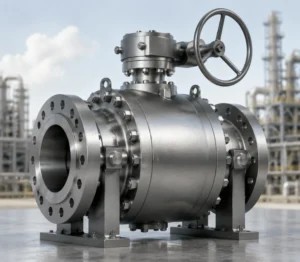
Trunnion-mounted ball valves cover NPS 1/2 to NPS 48 (DN1200) — a key differentiator from floating-ball designs. NPS 1/2 to NPS 12 (DN15–DN300) are typically stocked; NPS 14 to NPS 24 (DN350–DN600) are in the custom-stock cross-over zone; NPS 24 and above are almost entirely custom-made, with fewer than 12 factories globally capable of NPS 36 production. During a Middle East pipeline project sizing review, the client required DN900 Class 300 ball valves — this size has a flange OD of approximately 1.9 m and a single-piece weight of approximately 12 tonnes, exceeding standard container transport limits, ultimately requiring split shipment and on-site assembly.
Bore selection directly affects pipeline pressure drop and economics. Full bore ball valve resistance coefficient is approximately 0.01; reduced bore is approximately 0.2 — for a DN400 pipeline at design flow rate, switching from full bore to one size reduced bore creates pressure loss equivalent to a small auxiliary pump. I helped a chemical plant plan a steam distribution network where engineers initially selected DN300 reduced-bore valves to reduce cost; after four years of operation, the electricity surcharge from additional pressure drop averaged $8,400 per year, exceeding the price difference between reduced and full bore valves within four years.
Nominal bore also determines the valve flow coefficient (Cv value), which grows non-linearly with bore size. For API 6D standard trunnion ball valves: DN50 full bore Cv is approximately 34; DN100 approximately 145; DN200 approximately 560; DN400 approximately 2150. Reducing bore by one size typically reduces Cv by 40–60%. At $0.10/kWh electricity cost, reducing a DN400 to DN350 causes approximately 40% Cv loss, equivalent to approximately 18 kW of additional pump power consumption — adding approximately $11,000 per year in operating costs, which exceeds the $4,500 procurement price difference within one year.
ASME B16.10 specifies face-to-face dimensions for ball valves — changes in bore within the same pressure class cause F-F dimensions to change. Bore and pressure class must be locked together during the design phase, otherwise pre-fabricated pipe spool dimensions will be completely invalidated.
Common Materials
A216 WCB body material covers -29°C to 425°C; NACE MR0175 sets H₂S environment hardness limit at HB 235. I assisted in auditing a refinery where a batch of A216 WCB valve bodies was installed on H₂S-containing produced water pipelines without NACE MR0175 certification — after 8 months of operation, stress corrosion cracking appeared and the entire batch had to be replaced at a direct cost exceeding $200,000. WCB is the most common body material for Class 150–300 service, but sour service applications require NACE-certified material.
LNG terminals and cryogenic service at -162°C require A352 LC3 low-nickel steel, rated to -196°C. I observed an emergency procurement incident at a coastal LNG receiving terminal where WCB valve bodies were mistakenly ordered for LNG unloading arms — at -162°C, WCB impact toughness is near zero, and any shock load could trigger brittle fracture. A352 LC3 impact toughness at -196°C still meets ASME B16.34 requirements — this is a non-negotiable requirement for cryogenic service. Ball and stem are typically A182 F316 (forged) or A351 CF8M (cast); F316 contains 2–3% molybdenum, critical for chloride pitting resistance in seawater service. Fake “F316” with zero molybdenum content has appeared in informal supplier channels — procurement specifications must require mill certificates and reserve the right to conduct third-party testing.
Body welding procedures directly affect overall reliability. WCC carbon steel has a higher carbon equivalent (Ceq) than WCB, and AWS D1.1 mandates preheat to 150°C minimum when Ceq exceeds 0.40%, followed by post-weld heat treatment (PWHT). I reviewed a Southeast Asian gas processing plant project where WCC valve bodies were welded to pipeline without PWHT — after 18 months in service, transverse cracks appeared in the weld heat-affected zone (HAZ), approximately 25 mm in length. Emergency replacement of one DN300 Class 600 ball valve, including shutdown losses, exceeded $85,000 — whereas compliant PWHT costs only approximately $1,200 per weld joint, making the emergency replacement cost 70 times the prevention cost.
Internal coating thickness also affects corrosion resistance. API 6D requires carbon steel valve body internal flow passages to be coated with epoxy or Liquid Nylon at minimum 250 microns dry film thickness (DFT). During a Southeast Asian seawater treatment project, I found a batch of valves with epoxy coating at only approximately 80 microns — after 2 years of operation, pitting corrosion penetrated the valve body walls, requiring emergency replacement of 6 valves at approximately $48,000, far exceeding the cost savings from the thinner coating specification.
NACE MR0175 mandates maximum Brinell hardness HB 235 for H₂S environments to prevent stress corrosion cracking — valve body material certificates for sour service must state the actual measured hardness value, not merely declare “NACE compliant.”
API 6D Testing
Pressure Tests
API 598 specifies factory acceptance test procedures for pipeline ball valves: shell test pressure is 1.5 times rated pressure, seat test pressure is 1.1 times rated pressure. These two test pressures are different — and the seat test pressure is lower than the shell test pressure, which is a detail many people confuse. I witnessed a DN200 Class 600 ball valve factory test where the manufacturer held shell test pressure for 30 seconds then switched directly to seat test without any depressurization, causing the seats to undergo slight plastic deformation under shell pressure — the seat test showed leakage exceeding API 598 limits. This was not a valve quality defect but a test procedure error; when repeated correctly, the valve passed.
Hold times vary by valve size: DN50 and below require at least 15 seconds; DN300 and above require at least 60 seconds. During large-bore valve shell tests, body surface deformation and visible leakage must be monitored simultaneously. I helped debug a Southeast Asian oil and gas processing plant where a batch of Class 900 DN150 ball valves had hold times labeled only “30 seconds” — not extended to the required 60 seconds per ASME B16.34 — and one valve body weld showed hidden leakage that was not detected before shipment because the factory shortened hold time to meet a delivery deadline.
Shell testing preferably uses hydrostatic (water) rather than pneumatic testing because water’s incompressibility makes pressure easier to stabilize and the method is significantly safer — pneumatic testing is only used when the valve body cannot hold water (such as for dry service conditions), and API 598 Section 9 pneumatic test safety procedures must be strictly followed. I observed a dry nitrogen service project where a supplier conducted shell testing directly with nitrogen gas, and at 7.0 MPa test pressure the valve body burst — fortunately no personnel were injured, but nitrogen pneumatic testing at high pressure carries far higher risk than hydrostatic testing, and any high-pressure gas test requires protective barriers with personnel exclusion zones.
API 598 shell test hold times: NPS 4 (DN100) and below at least 15 seconds, NPS 6 (DN150) and above at least 60 seconds — a mandatory item in factory test reports and a key observation point during owner independent witnessing.
Leakage Standards
API 598 seat leakage testing uses the bubble method with four leakage rate classes: Class A is zero visible bubbles (most stringent); Class B is 60 bubbles per minute or less; Class C is 180 bubbles per minute or less; Class D is 600 bubbles per minute or less. PTFE soft seats in Class 150–300 service typically achieve Class B initially, but leakage rates progressively degrade with cycling. I tested a batch of Class 150 DN100 PTFE ball valves for open-close cycle life: after 300 cycles, sealing faces showed 0.4 mm depth cracks (26% of the 1.5 mm total PTFE thickness), measured leakage rate escalated from Class B to Class C; after 600 cycles, leakage deteriorated further.
A Southeast Asian crude oil terminal discovered after inlet line maintenance that 3 Class 300 DN200 ball valves in 5 years of service had leakage rates exceeding API 598 Class B limits (60 bubbles/min), with the highest measuring 280 bubbles/min — the operator required all same-batch valve seats upgraded to metal seats, at approximately $4,200 per seat replacement including pigging, disassembly, seat replacement, and reinstallation, totaling approximately $60,000 for the full upgrade. Had the selection phase anticipated PTFE wear rates in heavy crude oil service, metal seats would have reduced 10-year life-cycle cost by approximately 35% per valve.
HP natural gas transmission pipelines typically use metal-sealed ball valves rated for Class 1500 and above, with stable leakage rates at API 598 Class A or Class B and solid particle erosion resistance far exceeding PTFE. In a Central Asian natural gas export pipeline project, station valves using metal-sealed ball valves showed no seal degradation after 5 years of continuous operation, while adjacent reduced-bore valves with PTFE seats required seat replacement on average every 2 years. Metal-sealed ball valves in water injection stations (free water conditions) achieve 4–6 times the seal life of PTFE, reducing overall maintenance costs by approximately 60%.
DBB Function Tests
Double Block and Bleed (DBB) requires that both valve seats hold pressure independently and that the bleed port opens reliably — meaning each seat must separately pass API 598 seat leakage testing, and the bleed port flow area must meet design requirements. I participated in commissioning a North Sea offshore platform where a Class 600 DN150 DBB ball valve during commissioning revealed: upstream seat passed, downstream seat passed, but when the bleed port opened there was approximately 0.8 mm eccentric gap between seat and ball — caused by a ball-centering pin not precisely centered during assembly, resulting in the bleed port actual opening at less than 40% of design flow capacity during partial-open operation. The platform firewater system design depended on this bleed port’s maximum flow capacity, and this deviation required factory re-assembly.
The core of DBB function testing is verifying isolation integrity between the two seats. During DBB function testing, pressure should first be applied to the upstream seat and held while monitoring downstream seat leakage, then the test should be reversed. I observed at a chemical industrial park that maintenance teams frequently skip DBB function tests — they perform single-seat seal tests only, ignoring the interaction effect when both seats are simultaneously pressurized. When isolation was actually required for maintenance, the DBB valve failed to isolate, allowing process medium to bypass the seats into the downstream pipeline.
Stem anti-blowout and body-to-stem continuity resistance (10 ohms maximum) are mandatory requirements under API 6D. Anti-blowout is achieved through a tapered stem pilot and threaded gland locking nut — when it fails, the stem is ejected by internal pressure. The continuity resistance requirement prevents static charge accumulation. During a chemical industrial park supplier qualification review, I found that several low-cost suppliers lacked anti-blowout verification reports for their stem seal assemblies — such valves in solid-particle-laden media could generate friction static electricity and pose safety risks.
API 6D mandates stem anti-blowout devices and body-to-stem continuity resistance no greater than 10 ohms — valves below this resistance value in flammable media may accumulate static electricity and create ignition hazards; both parameters must be listed explicitly in procurement technical specifications.
Pipeline Uses
Midstream Pipelines
Class 600–900 natural gas transmission trunk lines (DN600–DN900 section) paired with ANSI 600–900 flanges, with design pressures typically 3–8 times higher than Class 300, represent the largest application scenario for trunnion-mounted ball valves. During an inland natural gas trunk line design review, the client insisted on Class 300 valves to reduce initial cost. Detailed pipeline fluid analysis showed maximum steady-state operating pressure of 6.8 MPa — which exceeds Class 300 rated pressure even at 38°C (approximately 2.0 MPa), a 3.4 times gap that failed to meet the safety factor requirement. The project was forced to re-procure Class 900 valves, increasing initial cost by approximately $340,000 but avoiding overpressure risk during operations.
Crude oil trunk lines typically operate at Class 300–600, with large valve quantities and maintenance windows constrained by pipeline batch scheduling. I audited a crude oil pipeline station where operations reported Class 300 DN400 ball valve Mean Time Between Repairs (MTBR) of only approximately 18 months. Investigation found the processed crude water cut reached 3% by volume at peak, with free water accumulating in low points of the valve body causing seat galvanic corrosion. Upgrading seat material from PTFE to RTFE (glass-filled PTFE) extended same-model valve MTBR to approximately 4 years, reducing maintenance costs by approximately 60%.
Long-distance pipeline stations are typically equipped with SCADA monitoring systems that continuously collect valve status and position feedback signals. ASME B31.8 classifies pipeline routing areas into 4 class locations based on population density (Class 1–4), with Class 4 areas (such as urban centers) requiring a design factor of 0.40 — twice that of Class 1 areas (0.72 vs 0.72). This means Class 4 sections must use higher pressure class valves with increased wall thickness. I found in a pipeline environmental impact assessment that an engineer had misclassified a Class 2 area (population density 5–25 persons/km²) as Class 1, causing insufficient wall thickness design for that section — later forcing pressure derating to meet safety factor requirements during operations.
Crude and Gas
Class 900–1500 wellhead installations (15.4–26.0 MPa) with H₂S, CO₂, and sand particle erosion represent the most demanding service conditions for trunnion-mounted ball valves. I have reviewed typical wellhead ball valve configurations for such service: Class 1500 DN65, A182 F316 ball surface welded with Stellite wear-resistant overlay, metal-seated, body material A216 WCC NACE MR0175 certified, A182 F316 stem — this combination is the standard specification for HP, HT, high-corrosion (H₂S-containing) wellhead service, and any downgrade risks rapid seal failure.
LNG receiving terminals and gasification facilities processing -162°C cryogenic LNG require A352 LC3 bodies — WCB is completely inadequate at this temperature. I observed an emergency shutdown incident at a coastal LNG receiving terminal where WCB valve bodies were mistakenly installed on LNG unloading arms — the LNG temperature of -162°C puts WCB well below its brittle-ductile transition temperature (approximately -20°C), where WCB Charpy impact energy approaches zero and any impact load could trigger brittle fracture of the valve body. A352 LC3 impact energy at -196°C still meets ASME B16.34 requirements — a non-negotiable baseline for cryogenic service selection.
Valves for H₂S-containing wellhead service require additional attention to Sulfide Stress Cracking (SSC) resistance. NACE MR0175 not only specifies hardness limits but also mandates critical value testing for materials under specific H₂S partial pressure combinations. ISO 15156 further refines material selection rules for acid gas fields under various pH and H₂S partial pressure combinations: when p(H₂S) times C exceeds 0.05, only A352 LC3, A182 F316, and a few other materials are permitted. I observed at a Middle Eastern sour gas field that A216 WCC valve bodies with NACE MR0175 certification still exceeded the critical value for A352 LC3 at actual measured p(H₂S) times C of 0.12, forcing batch replacement with higher-grade A352 LC3 material — early-stage procurement cost savings were far outweighed by emergency replacement expenses.
ASME B16.34 specifies impact toughness requirements for each material at extreme temperatures — A352 LC3 impact energy at -196°C far exceeds WCB, and selecting WCB for LNG service is a serious selection error that exposes the valve body to brittle fracture risk at cryogenic temperatures.
Emergency Shutoff
Completing closure within 5 seconds is the core requirement for Emergency Shutdown Valves (ESDV); API 6D specifies maximum 5 seconds from shutdown signal to full isolation — this is the last line of defense in pipeline safety protection. I observed an undersized actuator selection at a natural gas pipeline compressor station: to save cost, Class 300 electric actuators were chosen, but the pipeline design pressure was Class 600. Under normal operation the actuators barely operated the valve, but during compressor station transient pressure fluctuations exceeding Class 300 rated pressure, actuator torque was insufficient to close the valve within 5 seconds — forced shutdown for emergency rectification, with actuator replacement emergency procurement and construction costs of approximately $85,000, exceeding the $12,000 saved in initial selection.
ESDV actuator selection must satisfy Safety Integrity Level (SIL) requirements. IEC 61508 classifies safety functions into SIL 1–4, with pipeline ESDVs typically requiring SIL 2, corresponding to an average Probability of Dangerous Failure on Demand (PFDavg) no greater than 0.01 — meaning no more than 1% allowed probability of failure to operate per year. SIL 2 pneumatic actuators typically have response times of 0.5–2 seconds; hydraulic actuators 1–4 seconds; electric actuators 3–8 seconds. At the 5-second maximum closing requirement, electric actuators on large high-pressure valves require rigorous SIL verification. I observed a cross-border pipeline project where DN600 Class 600 ESDVs were equipped with electric actuators rated at 3.5 seconds closing time, but SIL calculations including seat friction uncertainty showed PFDavg of 0.018, exceeding the SIL 2 upper limit — forcing replacement with hydraulic actuators.
API 6D 2022 added quarterly ESDV periodic function test requirements: at least one simulated shutdown test per quarter to verify actuator response time and seal performance. A Chevron 2019 pipeline incident report documented an Alaska gas transmission line ESDV failing to close during an emergency shutdown due to long periods without testing — investigation found the ESDV had operated continuously for 29 months without any function tests, actuator lubricant had dried out, extending response time from the designed 3.5 seconds to 11 seconds, exceeding the API 6D 5-second limit. Following the incident report, API 6D was revised to mandate quarterly function tests, with test cycle records incorporated into pipeline operating permit review conditions.
API 6D trunnion-mounted ball valve selection fundamentally balances pressure class, bore size, body material, and testing standards — Class 150–300 small-bore PTFE soft seats deliver the best cost-to-performance ratio, Class 600–900 mid-pressure transmission lines require simultaneous locking of P-T combination values, and high-pressure wellhead and LNG cryogenic service allow zero downgrade flexibility. Every dollar saved during the selection phase may be repaid several times over during operations — or result in several times the loss if the wrong choice is made.


")