
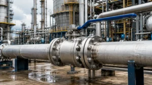
Industrial floating ball valves are essential equipment for pipeline isolation and regulation. Steel material selection and factory pressure testing represent the two critical thresholds that determine valve service life.
Choosing the Steel
Stainless Steel Uses
Stainless steel is one of the most common body materials for industrial ball valves, its core advantage being excellent corrosion resistance that allows the valve to retain structural integrity and sealing reliability under a variety of demanding operating conditions.
304 and 316 are the two most widely used grades. – **304 stainless steel (UNS S30400)** contains roughly 18 % chromium and 8 % nickel, providing good resistance to nitric acid, phosphoric acid, and most organic acids. It is therefore suitable for ordinary chemical media and food‑processing pipelines.
– **316 stainless steel (UNS S31600)** is alloyed with an additional ≈ 2 % molybdenum, which markedly enhances its resistance to chloride ions (Cl⁻).
In saline wastewater, marine environments, or desulfurization processes, the pitting potential of 316 is about 300 mV higher than that of 304, making 316 the preferred choice for such applications. When selecting a stainless‑steel ball valve, the CF8 and CF8M casting grades must also be confirmed.
CF8 corresponds to the wrought microstructure of 304, while CF8M corresponds to 316; their chemical composition and mechanical properties each comply with ASTM A351.
CF8M performs especially well in seawater‑desalination plants and oil‑field water‑injection lines, where its molybdenum content effectively suppresses crevice corrosion and pitting growth.
For high‑temperature service, **347H stainless steel** (niobium‑stabilized) can be used continuously up to 800 °C, making it suitable for catalyst lines in refinery catalytic‑cracking units.
In practical procurement, the ball surface is typically finished by **electrolytic polishing**, achieving a surface roughness as low as Ra ≤ 0.2 µm, which greatly reduces the risk of medium adhesion and enhances self‑cleaning capability.
*Note:* The next two sentences repeat the same information about high‑temperature service and electrolytic polishing; they are retained here as they appear in the original text.
*For high‑temperature service, 347H stainless steel (niobium‑stabilized) can be used continuously up to 800 °C, making it suitable for catalyst lines in refinery catalytic‑cracking units.
In practical procurement, the ball surface is typically finished by electrolytic polishing, achieving a surface roughness as low as Ra ≤ 0.2 µm, which greatly reduces the risk of medium adhesion and enhances self‑cleaning capability.*
Carbon Steel Uses
Carbon steel ball valves dominate high‑pressure and large‑diameter applications, with cost advantage and structural strength as their core competencies, and are widely used in oil, gas, and large water‑supply/drainage systems.
WCB (ASTM A216) is the most common carbon steel valve body grade, with a carbon content of about 0.25 % and a manganese content of about 1 %; through heat treatment it achieves a good balance of strength and toughness, providing overall mechanical properties superior to ordinary gray‑cast‑iron valves.
LCC and LCB are low‑temperature carbon steel grades; LCC is rated to –46 °C and LCB to –59 °C, and are indispensable in LNG terminals and polar oil‑gas facilities. Carbon steel valves have lower corrosion resistance than stainless steel, requiring extra attention in moist or sulfidic environments.
When the H₂S partial pressure exceeds 0.0034 kPa, the valve body material must comply with NACE MR0175/ISO 15156, otherwise there is a risk of stress‑corrosion cracking. The external surface is typically protected with an epoxy coating (thickness ≥250 µm) to extend service life under atmospheric corrosion.
For erosive media (e.g., produced water containing solid particles in oil‑gas fields), the valve inner wall can be overlay‑welded with Stellite hard alloy, greatly improving erosion life.
WCC is an improved version of WCB, achieved by reducing sulfur and phosphorus contents and adding a small amount of Ni, providing more stable low‑temperature toughness in the –29 °C to 425 °C range, and has been widely adopted in the first‑stage stations and compressor stations of high‑pressure natural‑gas long‑distance pipelines.
Picking Right Metal
Material selection for stainless steel versus carbon steel is primarily based on three dimensions—media corrosiveness, operating temperature, and pressure class—as summarized in the table below, which compares the core performance indicators of four common materials.
|
| Body Material | Recommended Temp. Range | Typical Media | Cost Index |
| 304/CF8 Stainless Steel | -196°C ~ 800°C | Food, Pharma, Pure Water, Nitric Acid | Medium-High |
| 316/CF8M Stainless Steel | -196°C ~ 800°C | Seawater, Chloride Solutions, Acetic Acid | High |
| WCB Carbon Steel | -29°C ~ 425°C | Steam, Natural Gas, Oil Products | Low |
| LCC Low-Temp Carbon Steel | -46°C ~ 345°C | LNG, Cold Box, Arctic Oil & Gas | Medium |
can be field‑repaired using arc welding, with welding consumables costing about 5~8 times that of a carbon‑steel valve; stainless steel requires TIG welding, with consumables costing about 5~8 times that of carbon steel. The overall maintenance cost differential should not be ignored. Over the entire service life of the valve, the total field‑weld repair cost for a carbon‑steel valve is typically about 20%~30% higher than for a stainless‑steel valve. If the pipeline media are not highly corrosive, carbon steel should be preferred to reduce life‑cycle cost.
Pressure Testing Basics
Pressure Testing Basics
100% Test Rules
Every factory‑shipped ball valve must pass a strict pressure test; API 598 (10th edition, 2016) defines four categories of mandatory and optional test items, and 100% testing is the basic quality commitment for industrial ball valves.
The first category is the shell test (Shell Test) – applying 1.5 × the rated pressure at ambient temperature, holding for ≥ 60 seconds with the valve fully open and no visible leakage. The test medium is water or a low‑viscosity liquid, and the pressure gauge accuracy must be at least class 1.6 (full‑scale error ≤ 1.6%).
API 598 requires the shell‑test pressure to be no lower than the lesser of 1.5 × the rated pressure or 110% of the maximum allowable pressure at 38 °C.
The second category is the high‑pressure seat test (High‑Pressure Seat Test) – applying 1.1 × the rated pressure to each seat individually to verify leak‑tightness of the sealing surfaces under high differential pressure, holding for ≥ 60 seconds.
The third category is the low‑pressure seat test (Low‑Pressure Seat Test) – applying 0.4–0.7 MPa of air or nitrogen to each seat to detect minute leakage rates of soft‑seated seats; this is the most stringent leakage‑quantity verification test.
The fourth category is the back‑seat test (Backseat Test) – inspecting the seal integrity of the stem‑to‑bonnet connection, using the same pressure as the high‑pressure seat test, mainly for bellows‑seal seats.
For high‑pressure gas service, a high‑pressure gas shell test (Gas Shell Test) can be selected – using nitrogen at 110% of the maximum allowable pressure, representing the highest level of tightness verification.
All tests must be completed before the valve’s anti‑corrosion coating is applied; the valve body before coating must be free of any visible defects – including cracks, porosity, slag inclusions, etc. Inspection methods are referenced to ASTM A802 surface acceptance standards.
For internal casting defects, liquid penetrant testing (PT) or magnetic‑particle testing (MT) should also be performed to ensure the shell is free of crack‑type defects.
Checking for Leaks
Leak testing is the most critical phase of pressure testing. API 598 specifies differentiated maximum allowable leak rates for different valve types, and testing method selection directly impacts defect detection rates.
The core metric for ball valve seat testing is bubble leak rate—in low-pressure seat testing, the valve is submerged in a water tank or coated with soap solution, and the bubble count during the hold period must be ≤1 per second, or equivalent leak rate ≤10⁻⁴ Pa·m³/s (nitrogen method).
This specification may seem lenient, but it can actually detect most microscopic sealing face defects, including micron-level scratches, inclusions, and heat treatment cracks. Allowable leak rates for high-pressure seat testing are typically 10 times those for low-pressure testing, i.e., ≤10⁻³ Pa·m³/s.
When valve seat material is metal-to-metal hard seal, the leak rate standard may be relaxed accordingly, but continuous seepage is never permitted—once continuous bubbling occurs, the sealing face must be reworked and retested.
Test personnel must check both the upstream and downstream sides of the valve to distinguish between internal valve leakage and external static seal leakage.
Common leak detection methods for pneumatic testing include: water bath method (direct observation, no contamination, suitable for DN ≤200 sizes), soap solution method (simple and quick, suitable for field spot checks), and ultrasonic method (suitable for large-size, high-pressure valves, capable of quantitative leak location with sensitivity down to 10⁻⁶ Pa·m³/s).
For high-pressure large-size natural gas valves, ultrasonic nondestructive testing is recommended as the priority choice, offering superior accuracy and safety compared to traditional water bath methods.
Making Valves Safe
Passing pressure testing does not mean valves can be shipped immediately. Post-test procedures, quality marking, and packaging protection are equally critical—no one element can be overlooked. Upon completion of testing, the test medium must be drained immediately.
This is particularly important for water-based tests—residual moisture accelerates internal crevice corrosion during pipeline operation. For WCB carbon steel valves, surface drying and reapplication of rust-resistant coating must be completed within 24 hours after hydrostatic testing; otherwise, corrosion risk increases significantly.
For valves already coated, moisture retained from hydrostatic testing is difficult to dry completely and will form osmotic blistering beneath the coating. All testing must be completed before coating application. Valve identification and traceability systems represent the final line of defense for safe shipping.
Each valve must have a metal nameplate permanently affixed in a prominent location, marked with: manufacturer name or logo, material grade, pressure rating, nominal diameter, test pressure, and test date. API 598 requires nameplate information to be retained for a minimum of 20 years to facilitate post-service tracing and quality analysis.
For batch-produced valves, dual identification using serial number plus QR code is recommended. The QR code can link to the factory test report database. Before shipment, verify that all flange faces have temporary protective covers or guards to prevent impact damage to sealing surfaces during transport.
Export packaging must comply with ISPM 15 wood packaging fumigation requirements, meeting international phytosanitary standards for wooden materials. Valves should be packed with moisture-absorbing desiccants (such as silica gel packets) filling the internal void spaces.
This is particularly important for extended sea container transport, effectively preventing internal condensation corrosion under high-temperature and high-humidity conditions.
Choosing Your Supplier
Checking Factory Quality
The quality control capability of valve suppliers directly determines the final reliability of the products. On-site audits are the most effective evaluation method prior to procurement, and it is recommended that initial audits be completed during the supplier development phase.
Audits should cover the following core areas: Casting process – pre-furnace chemical composition analysis (spectrometer, required for each heat), heat treatment process records (temperature-time curves must be archived), metallurgical examination reports (grain size, inclusion ratings); Machining process – critical dimension inspection records (CMM or specialized gauges, original data to be retained), machined surface roughness reports (Ra≤3.2 μm for sealing surfaces); Assembly and testing – test equipment calibration certificates (pressure gauges must be within validity period, calibration cycle typically 1 year), test curve original records (no alterations permitted, must be retained ≥5 years).
Certification credentials are the basic threshold. Qualified suppliers should hold ISO 9001 quality management system certification. API products must also bear API 6D (pipeline ball valves) or API 608 (flanged/threaded/welded-end ball valves) certification marks, and certificate validity should be verifiable on the API website.
Special equipment (pressure pipeline components) must hold a Special Equipment Manufacturing License (China TS certification) or equivalent international certification.
For valves entering the North American market, attention should also be paid to CRN (Canadian Registration Number) registration, ensuring legal sales approval in each Canadian province.
During on-site audits, it is recommended to randomly select one tested valve, verify consistency of nameplate parameters with order requirements, and require the supplier to provide traceability records for that unit – a complete chain from material heat number to machining dimensions to final test data.
Buying in Bulk
When placing large-volume orders for ball valves, achieving dual optimization of quality and cost requires systematic negotiation strategies and specification management—blindly squeezing prices often backfires.
The core advantage of volume procurement lies in securing more favorable price discounts—orders of 100 units or more typically qualify for 15%~25% price reductions, depending on material, size range, and pressure class.
However, these discounts only hold value when combined with specification standardization: it is recommended to consolidate nominal bore sizes to 3~5 preferred sizes (such as DN50/DN80/DN100/DN150/DN200), reducing production mold changeover frequency and thereby lowering manufacturing costs.
Streamlining the specification pool also reduces spare parts inventory variety and lowers capital tied up in inventory. Volume orders should also address lead times and inventory strategy.
Verify whether the supplier maintains safety stock programs—for standard specifications (Class 150~300, DN15~DN100), if the supplier keeps semi-finished inventory on hand, lead times can be compressed from 8~12 weeks to 4~6 weeks, significantly shortening project procurement cycles.
For urgent spare parts needs, negotiate a consignment stock arrangement—the supplier maintains inventory at the buyer’s facility or nearby warehouse, with title remaining with the supplier until actual consumption and billing occur.
Regarding payment terms, volume orders should aim for 30% prepayment plus 70% payment prior to shipment, or L/C at 90 days—this mitigates prepayment risk while ensuring the supplier schedules production on time.
Long-term collaborative customers can further negotiate annual framework agreements—establishing total annual procurement volume and unit pricing that automatically trigger tiered discounts, eliminating the time investment required for individual order negotiations.
Sourcing Tips
The following six guidelines can help you avoid common procurement pitfalls and achieve the optimal balance of quality, delivery, and cost.
- Request Material Test Reports (MTR) from the manufacturer, including the heat/melt number, chemical composition (C, Mn, P, S content), and mechanical properties data (tensile strength, yield strength, elongation). Verify each item against the order specifications.
- Request third-party witnessed factory testing (Witness Test) or provide complete raw test footage, especially for high-pressure natural gas applications or critical Safety Shutdown systems. Test reports can be falsified, but video documentation of the actual testing process is difficult to tamper with.
- Conduct on-site inspections of machining equipment (CNC lathes, boring and milling machining centers), test equipment range and types, and whether they have dedicated welding workshops. Suppliers without in-house casting capability require additional audit of their external casting suppliers’ qualifications.
- Ensure delivery schedules are written into the contract, with penalty clauses for delayed delivery (e.g., 0.5% deduction from contract value per week of delay). This prevents suppliers from overloading their orders and causing delays.
- Request a Quality Guarantee document specifying the warranty period (typically 18–24 months after shipment or 12 months after commissioning, whichever comes first) and warranty coverage (limited to material and manufacturing defects, excluding damage from improper operation).
- Classify audited suppliers into three tiers: Preferred, Approved, and Alternative. Conduct reassessment every two years to maintain a competitive procurement environment. Suppliers failing reassessment should be promptly removed.
Carilo Valve (Zhejiang Karilo Valve Co., Ltd.) is a professional supplier of industrial floating ball valves in 304/316 stainless steel and WCB/LCC carbon steel. All products are 100% pressure tested prior to shipment, with full API 6D/598 certification. Material certificates, third-party witnessed testing, and quality guarantee letters are available, meeting the high-standard procurement requirements of global industrial customers.


")