
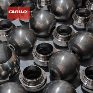
Soft seated ball valves are suitable for clean media, temperature ≤200°C, leakage class can reach ANSI Class VI; metal seated are suitable for particle-containing or high-temperature conditions (≤550°C), erosion resistant but leakage class is generally Class IV.
Selection should be based on media particle content, temperature range, and opening/closing frequency, and combined with sealing surface hardening treatment (such as HVOF spraying) to improve lifespan.
sealing method
Soft Seated
Polytetrafluoroethylene (PTFE) crystal melting point is 327 degrees Celsius, molecular weight is usually between 500,000 to 5,000,000. This polymer material exhibits physical stability in the range of minus 196 degrees Celsius to 200 degrees Celsius. Its friction coefficient is extremely low, with a value of only 0.04 in a dry friction state.
When choosing PTFE for forged steel ball valve seats, the material density needs to be maintained between 2.14 g/cm3 to 2.20 g/cm3. Its tensile strength should reach around 28 MPa. When the fluid media pressure rises above 2.0 MPa, pure PTFE is prone to cold flow phenomenon, leading to changes in the sealing shape.
In order to reduce deformation caused by cold flow, 15% or 25% glass fiber is added to polytetrafluoroethylene to make reinforced polytetrafluoroethylene (RPTFE). The linear expansion coefficient of this modified material drops to 6 times 10 to the power of negative 5 per Kelvin. In an environment of 150 degrees Celsius, its compressive strength is doubled compared to pure PTFE.
- PTFE (Polytetrafluoroethylene): density 2.16 g/cm3, water absorption rate lower than 0.01%, resistant to strong acids and alkalis.
- RPTFE (Reinforced Polytetrafluoroethylene): glass fiber ratio 15%, pressure bearing capacity supports Class 300 level.
- PEEK (Polyetheretherketone): melting point 343 degrees Celsius, hardness above Shore D 85, adapted to high pressures above Class 1500.
- Devlon V-API: water absorption rate is extremely low, only 0.08% at 20 degrees Celsius, mostly used for long-distance natural gas pipelines.
- Nylon 12 (Nylon): higher toughness, working temperature range is minus 40 degrees Celsius to 120 degrees Celsius.
In high pressure environments, PEEK material demonstrates excellent mechanical support. This semi-crystalline polymer can still maintain a tensile modulus of about 1.0 GPa at 250 degrees Celsius. Its radiation resistance dose can reach 1100 Mrad. In severe conditions such as oil drilling and production, PEEK valve seats can withstand a pressure difference of 70 MPa without fracturing.
After material properties are determined, they must be matched through processing accuracy. Usually, the roundness tolerance of a 4-inch ball should be limited to within 0.0127 mm. The ball surface roughness needs to reach between Ra 0.1 micron to Ra 0.2 micron.
The specific pressure generated by valve seat pre-tightening must be higher than the media pressure. If the media pressure is 10 MPa, the specific pressure on the valve seat sealing surface should be set between 15 MPa to 22 MPa. Excessively high pressure will cause the operating torque to rise significantly, affecting the lifespan of the actuator.
When calculating torque, the friction force between the ball and the valve seat must be included. Friction torque accounts for more than 60% of the total torque. For DN100 specification ball valves, under a 2.5 MPa pressure difference, the opening torque of the PTFE valve seat is approximately 120 Nm. When designing the matching actuator, a safety factor of 1.5 times is usually reserved.
- Ball roundness: 0.01 mm to 0.03 mm, ensuring uniform force on the contact surface.
- Surface hardness: the ball surface is usually plated with hard chrome, thickness 0.03 mm to 0.05 mm, hardness reaches HRC 55.
- Fitting clearance: the interference fit between the valve seat and the ball is usually set at 0.3 mm to 0.8 mm.
- Automatic pressure relief: when the valve cavity pressure exceeds the downstream pressure by 1.1 times, the valve seat should be able to automatically push open to relieve pressure.
API 607 fire safety standard requires soft seated ball valves to still possess sealing capability after a fire occurs. In a fire, soft seats will quickly decompose and disappear above 400 degrees Celsius. At this time, the metal edge on the valve seat bracket must fit tightly with the ball to form a secondary metal seal, preventing large-scale media ejection.
API 6D specification has strict quantification for leakage amount. Soft seated valves must reach ISO 5208 Class A standard, which means in a continuous 2-minute pressure test, the number of bubble leaks is zero. Tests usually use dry air or nitrogen. The test pressure is set at 1.1 times the maximum rated working pressure.
Molecular structure determines the service life of the seal. The C-F bond energy in the PTFE molecule is extremely high, reaching 485 kJ/mol. This stable molecular chain allows the material to not easily undergo natural aging over an operating cycle of more than 10 years.
When the flow velocity exceeds 5 meters per second, tiny impurities carried by the fluid will produce an erosion effect. If the hardness of impurities exceeds Shore D 60, it will leave permanent scratches on the soft seat surface. For high flow velocity conditions, an anti-erosion ring made of stainless steel is usually added to the front of the valve seat.
- Sealing lifespan: can reach 20,000 to 50,000 opening and closing cycles in a laboratory environment.
- Cleaning requirements: degreasing treatment is required before assembly to ensure no particles above 0.1 mm remain.
- Temperature rise speed: the heating rate should be controlled within 10 degrees Celsius per minute to prevent the generation of thermal stress cracks.
The thermal expansion rate of polymers is 10 times higher than that of stainless steel. When the temperature rises from 20 degrees Celsius to 150 degrees Celsius, valve seat volume expansion will cause the torque to increase by more than 30%. Sufficient space must be reserved in the design to compensate for thermal expansion and contraction. 2 to 4 pieces of disc springs are often installed on the back of the valve seat to provide continuous thrust.
Compared to casting parts, forged steel has better fatigue strength under 40 MPa high pressure. 17-4PH stainless steel is mostly used for the valve stem part, with a tensile strength exceeding 1000 MPa. This ensures that under extremely high opening torque, the valve stem will not undergo torsional deformation.
The coaxiality error during the assembly process must be controlled within 0.05 mm. The flatness tolerance of the valve seat bracket needs to reach 0.02 mm. Even a tiny eccentricity will cause abnormal wear on one side of the valve seat. In the first hydraulic test after assembly is completed, the pressure needs to rise to 1.5 times the rated value and maintain pressure for 30 minutes.
Metal Seated
Metal seated ball valve sealing surfaces often use Stellite 6 cobalt-based alloy surfacing, with surface hardness distributed between HRC 40 to 45. For strong abrasive slurry conditions containing solid particles, the bonding strength of the tungsten carbide coating with the substrate is increased to above 70 MPa through the High Velocity Oxygen Fuel (HVOF) process. The coating thickness is usually precisely controlled between 0.15 mm to 0.25 mm.
Tungsten carbide (WC) coating hardness reaches HRC 68 to 72. When handling crude oil with a sand content exceeding 5% or catalysts in catalytic cracking units, the high-hardness surface can resist particle erosion at flow velocities of 15 meters per second. Chromium carbide coating performs more stably in extreme high temperature environments above 540 degrees Celsius, preventing adhesive wear of metal at high temperatures.
- Stellite 6: Cobalt-based alloy surfacing, withstands 500 degrees Celsius, excellent oxidation resistance.
- Tungsten Carbide (WC): Extremely high hardness, strong wear resistance, adapted to abrasive slurries.
- Chromium Carbide: Excellent heat resistance, can maintain structural stability below 800 degrees Celsius.
- Electroless Nickel Plating (ENP): Thickness about 0.05 mm, improves chemical corrosion resistance of the substrate.
When the temperature rises above 400 degrees Celsius, the matching degree of expansion coefficients between the ball and the valve seat determines the smoothness of opening and closing. When selecting A105 or F316 substrates, a thermal expansion compensation gap of 0.05 mm to 0.1 mm must be reserved in the processing stage. Design failure will cause the ball to expand and lock up in a high temperature environment, and the operating torque will instantly soar from the rated 500 Nm to over 2000 Nm.
| Leakage Class Classification | Allowable Leakage Amount (Water Test) | Testing Standard Basis |
|---|---|---|
| Class V | 5 times 10 to the power of negative 4 ml per inch diameter per psi | ANSI/FCI 70-2 |
| Class VI | Depends on nominal diameter (e.g., 27 drops per minute for 4 inches) | ANSI/FCI 70-2 |
| ISO Rate B | 5 times 10 to the power of negative 3 cubic mm per second times DN | ISO 5208 |
| API 598 Class | A certain number of drops allowed, specifically calculated based on diameter | API 598 |
The ball and the valve seat are paired and ground on a dedicated grinding machine with bidirectional rotation, with abrasive grit size gradually refined from 400 mesh to 1200 mesh. The contact surface after grinding is checked by color coating, and the contact area percentage must reach over 90% to ensure Class V sealing under a 10 MPa pressure difference.
Usually, 12 to 24 sets of disc springs made of Inconel 718 material are arranged on the back of the valve seat. The initial pre-tightening specific pressure provided by the springs should be set between 10 MPa to 15 MPa. In Class 900 or Class 1500 high-pressure conditions, fluid pressure will push the ball to squeeze the downstream valve seat in the direction of displacement, and this mechanical boosting effect will make the sealing specific pressure increase linearly as the pressure rises.
The ball roundness error should be controlled within 0.01 mm, ensuring surface contact with the valve seat throughout the 90-degree rotation full stroke. If the roundness deviation exceeds 0.05 mm, local high points will appear on the sealing surface, leading to coating peeling in frequent opening and closing.
When selecting the actuator, the friction coefficient of metal seals is usually taken as 0.25 to 0.45. Compared to soft seals, the rotation torque of metal seated ball valves of the same caliber is more than 2 times higher. For a DN200 specification Class 600 forged steel ball valve, it is recommended to configure a pneumatic or electric head with a torque not lower than 3500 Nm, and reserve a torque reserve coefficient of 2.0 times or more.
- Ball hardness: Usually HRC 2 to 5 higher than the valve seat hardness to prevent seizure of the same material.
- Valve seat bracket: Uses F316 or 17-4PH forgings, tensile strength must reach 800 MPa.
- Surface roughness: Needs to reach Ra 0.05 micron after grinding, presenting a mirror effect to the naked eye.
- Sealing type: Uni-directional or Bi-directional sealing is optional.
In oxygen valve applications, metal seated components must undergo strict degreasing and non-destructive testing. Surface coatings cannot contain any impurities that cause spontaneous combustion, and the coating bonding strength must be tested by a bending test. Under the flushing of 20 MPa pure oxygen fluid, the surface scratch depth should be less than 2 microns after 1000 cycles of operation for the tungsten carbide coating.
Inconel 625 or XM-19 high-strength alloys are usually used for the valve stem part. These materials have excellent torsional fatigue performance under high temperature and high pressure. The stuffing box part mostly uses flexible graphite with 316 steel wire, maintaining volume stability at 500 degrees Celsius. According to API 622 specification, its external leakage should be controlled within 100 ppm.
- Impact test: Substrate needs to meet the requirement of 27 Joules impact work in an environment of minus 29 degrees Celsius.
- Coating hardness gradient: A hardness gradient must be formed from the substrate to the surface layer to prevent brittle fracture.
- Coating bonding strength: Ensure the bonding strength is greater than 10000 psi through a tensile test.
In long-term operation, micron-sized particles in the fluid will be embedded between the grinding surfaces. The Scraper Seat design of the metal seal can scrape off attachments when the ball rotates. This structure can effectively prevent ball scratches when handling pulp or polysilicon powder media, extending the maintenance cycle from 6 months to over 24 months.
For ultra-high temperature 800 degrees Celsius blowdown valves in the power industry, the sealing surface needs special heat treatment processes. The ball and the valve seat undergo cyclic thermal aging treatment before assembly to eliminate residual stress caused by a 600 degrees Celsius temperature difference. The deformation amount of processing accuracy after heating needs to be maintained within 2 microns, ensuring that no jamming occurs in the hot state.
When assembling metal seated valves, the inside of the valve cavity must be inspected by endoscope, and any metal chips or weld slag are strictly prohibited. The initial test pressure is set at 1.5 times the rated value, and the pressure holding time is usually set at 15 to 30 minutes according to API 6D requirements. For high-requirement conditions, helium mass spectrometry leak detection is also required, and the leak rate should be lower than 1 times 10 to the power of negative 6 mbar·L/s.
media condition
Impurities & Hardness
Solid impurities in the fluid will produce a wear effect similar to sandblasting under a 15 MPa pressure difference, and particles with a particle size of only 10 microns can easily physically embed into the PTFE valve seat surface. This penetration makes the soft seal lose its original rebound compensation performance, and a leakage channel with a width exceeding 0.1 mm is subsequently generated on the sealing surface, leading to complete failure of the valve in a short period of time.
The Mohs hardness of quartz sand is 7, and the Vickers hardness reaches 1100 HV, while the hardness of common stainless steel 316 material is only about 200 HB. Physical cutting generated when the two contact will lead to scratches up to 0.5 mm deep. In order to deal with this damage, the ball surface must be hardened by High Velocity Oxygen Fuel (HVOF) technology.
- Tungsten Carbide (WC-Co) coating thickness needs to be precisely set between 0.15 mm to 0.25 mm.
- The bonding strength of the spray layer with the substrate must exceed 70 MPa to prevent large-scale peeling caused by particle impact.
- Surface hardness needs to be maintained in the extremely high range of HRC 68 to HRC 72.
- Coating roughness should reach Ra 0.1 after grinding with a diamond grinding head to reduce the friction coefficient.
- The valve seat spring uses Inconel X-750 material to ensure stable sealing pre-tightening force still at 350 degrees Celsius.
When the media solid content reaches 5%, the friction torque between the ball and the valve seat will increase by about 40% compared to clean conditions. In DN150 specification ball valves, the opening torque generated by sand-containing crude oil often leaps from the rated 800 Nm to 1150 Nm, exceeding the output range of conventional actuators.
Particles with a particle size between 50 microns to 150 microns are most likely to accumulate in the gap on the downstream side of the valve seat. When the spring compensation space is filled with debris, the valve seat will be stuck in the fixed groove and unable to move. At this time, the metal seated valve seat needs to add self-cleaning guide grooves, using a flow velocity of over 15 m/s to wash away accumulated fine powder, ensuring the followability of the sealing surface.
- All soft seal solutions must be abandoned when coal tar slurry solid content exceeds 30%.
- When particle compression strength is greater than 60 MPa, the ball-seat pairing grinding process needs to be adopted.
- The valve closing members need to have 0.5 mm grade scraping edges to cut off attached crystals.
- Two friction-reducing gaskets need to be installed at the valve stem seal to reduce running friction by more than 15%.
The velocity of gas-solid two-phase flow often reaches 30 m/s, and the erosion rate reaches its peak when the particle impact angle is between 20 degrees to 30 degrees. When there is no lining protection, the wall thickness reduction of a carbon steel valve body can reach 2.5 mm per year. For such conditions, a 3 mm thick hard alloy protective layer must be surfaced on vulnerable parts of the valve cavity to extend the service cycle of the shell.
Shale gas fracturing conditions are often accompanied by 20 mesh to 70 mesh proppant. Ceramic spherical particles with a diameter of 0.2 mm to 0.8 mm will be sandwiched between the ball and the valve seat at the moment of closing. The soft seated valve seat will undergo local tearing after being compressed, and the damaged area often exceeds 5 square millimeters. The “scraper” structure of the metal seat can push away more than 90% of the deposited particles.
For high-viscosity media with a viscosity exceeding 500 cSt, the hard-to-hard sealing surface cuts through the viscous liquid film through a pre-tightening force of 300 N. When the condition temperature rises to 500 degrees Celsius, the hardness of tungsten carbide will plummet due to oxidation. The hardening layer should be replaced with chromium carbide (Cr3C2-NiCr) at this time, which can maintain a hardness of HRC 60 at high temperatures, and the oxidation resistance layer possesses self-healing capability.
| Particle Type | Particle Hardness Value | Recommended Hardening Technology | Expected Cycle Life |
|---|---|---|---|
| Fine Coal Powder | 400 HB | Surface Hard Chrome Plating | 20,000 times |
| Alumina Powder | 1800 HV | Industrial Ceramic Lining | 5,000 times |
| Silica Sand | 1200 HV | Tungsten Carbide (HVOF) | 15,000 times |
| Metal Iron Filings | 250 HB | Stellite 6 Surfacing | 30,000 times |
Under a 6.3 MPa pressure difference, the leakage amount reaching Class V level requires less than 0.1 ml/in per minute. This relies entirely on high-precision grinding machines to perform pairing treatment of the ball and valve seat for over 24 hours. Catalyst particles in the media are often distributed between 40 microns to 80 microns, and if there is no dust-proof structure, fine particles entering the sealing ring groove will cause the valve seat to tilt.
When the valve opening frequency exceeds 10 times/day, the hardening layer must be thickened to deal with physical loss. In strong acids containing 10% solid impurities, the annual corrosion rate of Hastelloy C276 substrate can be controlled below 0.05 mm. This material selection plan solves the pitting corrosion problem in acidic fluids while taking hardness into account.
High-pressure oxygen conditions have extreme regulations for media cleanliness. If trace grease or metal particles are mixed in the media, sparks generated by high-speed impact will trigger violent oxidation reactions. Metal seated valve seats must implement strict degreasing standards, and grease content must be lower than 100 mg/square meter, which is a hard bottom line to ensure safe operation of the system.
Chemical Polarity & Corrosion Rate
When handling non-polar aromatic hydrocarbon fluids such as toluene and xylene, the volume swelling rate of conventional rubber sealing rings often exceeds 15%, leading to the operating torque doubling within 48 hours. Choosing perfluoroelastomer (FFKM) can compress the swelling rate to within 2% in a 250 degrees Celsius environment.
The molecular chain of soft seated PTFE will undergo degradation in strong oxidizing media. Concentrated sulfuric acid or fuming nitric acid with a concentration exceeding 98% will strip away fluorine atoms, making the sealing surface brittle and generating cracks with a depth of 0.2 mm. Monel 400 alloy is selected as the substrate for metal seated valves, and its annual corrosion rate in a reducing acid environment is lower than 0.127 mm, maintaining the integrity of the sealing surface.
Chloride ion concentration is the indicator that determines the pitting corrosion rate of stainless steel valve bodies. In circulating water with a chlorine content of 3000 ppm, the passivation film on the surface of 304 stainless steel will be locally broken down within 72 hours. Choosing duplex steel 2205 material, its Pitting Resistance Equivalent Number (PREN) value needs to reach 35 or more.
- The corrosion rate of Hastelloy C276 in 10% boiling hydrochloric acid is only 0.5 mm/a.
- Titanium alloy Gr.2 is suitable for wet chlorine conditions at room temperature, and the thickness of the titanium dioxide film formed on the surface is about 10 nanometers.
- Nickel-based alloy Inconel 625 has an oxidation-resistant layer weight gain of less than 0.1 mg/cm² at 600 degrees Celsius.
- 316L stainless steel needs to control the flow velocity below 1.5 m/s in 50% sodium hydroxide solution to prevent erosion corrosion.
- Fluorine-lined ball valve (PFA) lining thickness should not be less than 3 mm to prevent highly permeable media from penetrating the substrate.
Small molecule media such as hydrogen exhibit strong permeability under 20 MPa high pressure. The internal microporous structure of polymer seals will lead to a gas passage rate of 10 to the power of negative 7 cubic centimeters per second. Metal seated ball valves paired with SPW flexible graphite packing can reduce the leak rate to the magnitude of 10 to the power of negative 9.
Acidic oil and gas conditions must comply with the NACE MR0175 standard. When the hydrogen sulfide (H2S) partial pressure exceeds 0.0003 MPa, the hardness of carbon steel forgings must be strictly limited to below HRC 22. Metal grain boundaries exceeding this limit value will produce stress corrosion cracking (SCC), and the crack expansion speed can reach 1 mm/month in a humid environment.
| Media Chemical Composition | Suggested Material Combination | Corrosion Allowance Setting | Sealing Surface Hardness |
|---|---|---|---|
| 98% Concentrated Sulfuric Acid | Hastelloy B2 / Metal Seated | 1.5 mm | HRC 50 |
| 37% Hydrochloric Acid | Hastelloy C276 / PFA Lined | 3.0 mm | Not Applicable |
| Seawater / Brine | Aluminum Bronze / Monel K500 | 2.0 mm | HB 280 |
| Wet Hydrogen Sulfide | 20# Forged Steel (HIC Test) / 316 Surfacing | 6.0 mm | HRC 22 |
| Gaseous Chlorine | Carbon Steel + Nickel-based Alloy Trim | 1.0 mm | HRC 45 |
When the ball uses stainless steel and the valve seat uses copper alloy, the potential difference is as high as 0.3V or more. In salt spray conditions, the copper alloy valve seat at the anode part will undergo serious dezincification corrosion. Valve internals must maintain consistent potential sequences, or block electron transfer through insulating coatings.
The pH value fluctuation of the media directly affects the self-healing ability of the passivation film. Under strong acid conditions with a pH value below 3, the repair speed of the metal sealing surface is lower than the destruction speed. Choosing ceramic (ZrO2 or Al2O3) balls and valve seats provides extremely high chemical stability. In 15% hydrofluoric acid media, ceramic parts can maintain zero leakage records for more than 5 years.
- Ultra-high molecular weight polyethylene (UHMWPE) wear resistance is 7 times that of carbon steel.
- The tensile strength of polyetheretherketone (PEEK) is maintained at about 100 MPa at 200 degrees Celsius.
- Pure nickel Ni201 has a corrosion rate of less than 0.002 mm/a in high-concentration alkaline solutions.
- Zirconium material Zr702 shows near zero corrosion for acetic acid below 200 degrees Celsius.
- Silver sealing rings are commonly used in fluorine gas pipelines, forming a stable silver fluoride protective layer.
Carbon steel performs excellently in dry chlorine, but after the moisture content exceeds 40 ppm, the generated hydrochloric acid will make the corrosion rate soar 100 times. A corrosion allowance of 3.2 mm to 6.4 mm needs to be reserved inside the forged steel ball valve cavity to ensure a 20-year design life.
In high-pressure oxygen conditions, the media polarity and static electricity generated by metal friction are very likely to trigger oxidation reactions. Metal seated valve seats must undergo degreasing treatment with a grease content lower than 1 mg/100 cm². A stainless steel spring must be installed between the valve ball and the valve stem to achieve conductive connection, and the resistance value should be controlled below 10 ohms.
When acidic fluid velocity increases from 2 m/s to 10 m/s, the protective film on the metal surface will be destroyed by mechanical shear force. The inner wall of the metal seated ball valve flow passage needs to be sprayed with a 0.3 mm thick chromium carbide coating, using its 1200 HV hardness to resist high-speed erosion of the fluid.
Polar solvents such as methanol have a strong swelling effect on fluorine rubber. In an environment of 80 degrees Celsius, the elongation at break of fluorine rubber O-rings will drop from 200% to 80%. The seat back seal for such conditions needs to be changed to flexible graphite sandwiched with 316L stainless steel foil, maintaining sealing compression through mechanical compression force.
Viscosity & Polymerization
When fluid viscosity reaches 500 cSt or more, an adsorption film with strong shear resistance will form on the ball surface. Under crude oil vacuum residue conditions, the instantaneous break-away torque required to open the valve is usually 2.2 times the conventional water test value.
The destructiveness of this adhesion to soft seated valves is particularly prominent during the room temperature starting phase.
- The edge of the scraping metal valve seat is processed with sharp edges of 0.3 mm to 0.5 mm.
- The contact specific pressure between the seal pairs is set above 35 MPa to pierce the high-viscosity oil film.
- For polyether polyol conditions, the spring compensation amount at the back of the valve seat needs to be reserved for 2 mm to 4 mm.
- The valve stem uses 17-4PH precipitation hardening stainless steel to withstand excess torque exceeding 1500 Nm.
- The Cavity Filler reduces the dead space to less than 2% of the total volume.
In butadiene self-polymerization conditions, granular polymers are produced if the residence time of the monomer in the valve cavity exceeds 24 hours. The volume expansion pressure of this solid substance reaches 40 MPa, enough to crush a hollow ball with a wall thickness of less than 10 mm.
Media easily undergoes molecular chain growth in a high temperature environment above 200 degrees Celsius, forming viscous gel. In polyethylene production lines, materials with a melt index (MI) of less than 0.5 will completely solidify when cooling down during shutdown, “welding” the ball and the valve seat together. When starting again, the 2000 Nm torque output by the actuator will act on the contact surface of the valve seat and the ball. The metal seal uses the HRC 70 hardening layer hardness to counter this tearing force, avoiding peeling of the sealing surface.
The heat released by the polymerization reaction will cause the local temperature to rise by 50 degrees Celsius within 10 minutes, and this thermal shock will cause uneven thermal expansion of the valve seat sealing ring.
- The fit clearance between the metal valve seat ring and the ball is controlled within 0.02 mm.
- The valve seat sealing surface is sprayed with a chromium carbide coating, and the friction coefficient is maintained at about 0.2 at high temperatures.
- A double-track graphite ring seal is adopted on the back of the valve seat to resist penetration of polymer monomers.
- The valve body adopts a three-piece forged structure, and the internal flow passage undergoes Ra 0.4 grade mirror polishing.
- The bottom support bearing adopts metal composite material, and the unit pressure bearing capacity reaches 120 MPa.
The service life of valves in asphalt transport pipelines is usually less than 50 cycles if soft seals are used. The viscosity of asphalt at 150 degrees Celsius is about 200 cSt, but it will soar to over 10000 cSt when cooling to 80 degrees Celsius.
Fine polymer particles in the media will accumulate on the ball surface, forming a fouling layer with a thickness of about 0.1 mm. During the closing process of the soft seated ball valve, the PTFE valve seat will press these fouling layers into the interior of the seal, causing permanent plastic deformation of the sealing surface. The scraper structure of the metal seated ball valve contacts the ball at a 15-degree tangential angle during rotation, removing surface fouling like a bulldozer and maintaining the cleanliness of the metal contact surface.
When handling high-concentration mud or polymer-containing fluid, the pre-tightening force of the single-side valve seat needs to reach 8000 N or more. Too small a pre-tightening force will let solid debris in the media enter the space behind the valve seat. Once the polymer solidifies in the spring gap, the valve seat will lose its compensation function, leading to serious leakage of the valve during pressure fluctuations.
- The hardness of the scraping edge must be more than 3 times higher than the hardness of the polymer after solidification.
- The valve stem anti-blowout structure must withstand the 1.5 times rated pressure impact generated by media polymerization.
- For easily self-polymerizing media, the valve needs to be configured with intermittent steam purging interfaces.
- The sealing surface grinding accuracy needs to reach 2 light bands, ensuring no visible bubbles under 6.3 MPa pressure difference.
- The valve seat bracket uses XM-19 high-strength alloy to prevent yield deformation under high-viscosity loads.
The statistical data of a chemical plant showed that after replacing with metal seated ball valves, the frequency of unplanned shutdowns in the styrene unit was reduced by 80%. The original soft seated valves frequently experienced opening and closing jams every month due to physical embedding of polymers on the sealing surface.
Under the full open state of DN100 specification, the pressure loss of 3000 cSt media flowing through the valve is 15% higher than that of water. Steps and gaps in the flow passage will induce vortices and intensify local polymerization reactions. The flow passage of the forged steel ball valve needs to undergo full bore butt welding treatment, eliminating all tiny grooves that may cause material stagnation.
temperature range
Pressure & Temperature Limits
The ASME B16.34 pressure-temperature rating table determines the physical working boundaries of the A105 forged steel valve body. The Class 150 level allows a bearing pressure of 1.96 MPa at 38 degrees Celsius, and when the environment rises to 200 degrees Celsius, due to metal strength decay, this value is forcibly reduced to 1.38 MPa.
The load limit of the soft seated valve seat drops non-linearly with rising temperature. The compressive strength of the PTFE valve seat at 120 degrees Celsius is only about 45% of that at room temperature. Once it exceeds 150 degrees Celsius, the polymer chain segments undergo slip, and the ball will sink into the valve seat by more than 0.3 mm, leading to the opening torque soaring to 2.5 times the rated value.
- RPTFE adds 15% glass fiber, and can still maintain a compressive strength of over 14 MPa at 200 degrees Celsius.
- The hardness of PEEK material still stays above 80 Shore D at 250 degrees Celsius, far exceeding conventional plastics.
- The impact toughness of Devlon V-API in an ultra-low temperature environment of minus 50 degrees Celsius is 3 times higher than that of common nylon.
- Soft seated ball valves undergo airtightness testing at 1.1 times the rated pressure, and must meet the zero bubble passage standard.
- Polymer valve seats will undergo thermal degradation above 230 degrees Celsius, releasing corrosive hydrogen fluoride gas.
Media pressure in conditions above 300 degrees Celsius will cause continuous changes in the microscopic dimensions of the valve body. The linear expansion coefficient of F316 stainless steel is 16.0 times 10 to the power of negative 6 per degree Celsius. For a ball with a 200 mm diameter, the diameter will physically expand by about 1.28 mm under a 400-degree temperature difference.
Metal seated ball valves must rely on this expansion allowance for structural reservation. A compensation gap of 0.08 to 0.15 mm is usually set between the ball and the valve seat. If there is no such mechanical redundancy, once the valve cools after closing at high temperature, the contraction stress will lock the ball tightly to the valve seat bracket, causing physical jamming.
- Stellite 6 alloy can still maintain a hardness of about 35 HRC at 650 degrees Celsius high temperature.
- The bonding strength of HVOF tungsten carbide spray coating usually exceeds 70 MPa, enough to resist fluid flushing at 20 meters per second.
- Chromium carbide coating is specifically for the range of 540 degrees Celsius to 800 degrees Celsius to prevent the coating from peeling in high temperature oxidation environments.
- The elasticity decay rate of Inconel X-750 disc springs installed on the back of the metal seated valve seat is lower than 5% at 400 degrees Celsius.
- The packing at the valve stem seal should choose more than 5 rings of flexible graphite rings, and its density should be controlled at 1.12 grams per cubic centimeter.
The friction coefficient of metal seal pairs fluctuates between 0.35 to 0.5 at 350 degrees Celsius. In contrast, soft seals are only 0.08 at room temperature. Under the same pressure, the thrust of the scotch yoke actuator selected for metal seated valves must increase by more than 150%.
Abnormal pressure rise inside the valve cavity is a bomb often overlooked by soft seated structures. When the valve cavity is filled with water and closed, for every 1 degree Celsius increase in ambient temperature, the cavity pressure will surge by 13 to 15 bar. If the valve seat does not have an automatic pressure relief function, this internal pressure will directly tear the 5 mm thick polymer sealing ring.
- API 598 standard allows metal seated valves to have a tiny leakage under 6 bar air pressure, usually 10 drops per minute per inch of diameter.
- The wall thickness of Class 2500 level forged steel valve bodies has a fatigue life set at 20,000 times under 42 MPa high pressure cyclic load.
- The O-ring between the valve seat support ring and the valve body must be replaced with a stainless steel spiral wound gasket above 200 degrees Celsius.
- 17-4PH high-strength stainless steel valve stems need to undergo H1150D double aging treatment to balance tensile strength and ductility.
- The erosion rate of fluid shear force on soft seat edges at a 15-degree opening angle is 8 times that of the full open state.
Cryogenic deep-cooling conditions have extremely strict requirements for the molecular structure of materials. Liquid nitrogen media at minus 196 degrees Celsius requires the valve to be equipped with a 250 mm to 400 mm long neck extension cover. This is to use physical heat conduction characteristics to ensure that the packing temperature at the top of the valve stem is maintained above 0 degrees Celsius, preventing the seal from icing failure.
The forging process eliminates common shrinkage holes and sand eyes found in casting parts at the molecular level. Under high-pressure thermal cycle conditions, the dense organization of forgings makes the thermal fatigue crack initiation time 3000 hours later than that of castings. The creep strength of Class 1500 level forged steel ball valves at 425 degrees Celsius determines its service years.
- The surface roughness of the nickel-based alloy spray-welded layer must be ground to Ra 0.2 or even 0.1 to ensure airtightness.
- The ball roundness tolerance should be controlled within 0.02 mm, otherwise it will lead to uneven force on the sealing surface and generate local wear.
- During 3000 psi high pressure testing, the contact specific pressure between the valve seat and the ball must be constant at 1.25 times the media pressure.
- The pre-tightening torque of valve cover bolts must be precisely calculated according to the ASME PCC-1 standard to prevent high temperature creep leading to external leakage.
- The spring opening pressure of the automatic pressure relief valve seat is usually set in the pressure difference range of 0.2 MPa to 0.5 MPa.
Under wear conditions with frequent opening and closing, the average error-free operation time of soft seals is usually only 500 to 1200 cycles. Metal seals can push this data up to over 5000 times by performing supersonic spray hardening on the seal pairs. For particle-containing media with flow velocity exceeding 7 meters per second, metal seals are the only reliable barrier to maintain continuous operation of the production line.
Hardness Matching & Thermal Expansion
In the design of metal seated ball valves, the hardness difference between the ball and the valve seat must be maintained between 5 to 10 HRC to prevent intermolecular bonding of the same metal material during squeeze friction. When using the High Velocity Oxygen Fuel (HVOF) process, tungsten carbide coating particles hit the forging surface at a speed of over 600 meters per second, forming a dense layer with a thickness of 0.15 mm to 0.25 mm.
The mechanical bonding strength of this coating usually exceeds 70 MPa, and even with frequent switching under a high pressure difference of 3000 psi, physical peeling will not occur. If both the ball and the valve seat choose 68 HRC tungsten carbide coating, the sealing surface will cause the valve to be scrapped in a very short time due to seizure.
- After the sealing surface is ground, the surface roughness must be better than Ra 0.2 to ensure the conformity of the metal contact surfaces.
- The roundness error of the ball needs to be limited within 0.015 mm to prevent high-pressure fluid from generating erosion at the gaps.
- The hardness decay rate of the Stellite 6 surfacing layer at 500 degrees Celsius is lower than 15%, maintaining at about 35 HRC.
- When selecting Inconel 718 material for the valve seat support ring, its yield strength at high temperatures can reach over 1000 MPa.
- In high temperature oxidation environments of 800 degrees Celsius, the thickness of the oxidation scale on the chromium carbide coating surface is only micron-sized.
Material expansion caused by high temperature conditions will produce physical squeezing on the match of seal pairs. F316 stainless steel forgings expand by 0.0016 times for every 100 degrees Celsius increase in temperature. For a 250 mm diameter ball valve, the physical increment of the ball diameter reaches 1.6 mm under a 400-degree temperature difference.
If the thermal expansion coefficients of the valve body and internals do not match, it will lead to the valve seat pre-tightening force losing balance. The expansion coefficient of carbon steel A105 is about 12 times 10 to the power of negative 6, while stainless steel F316 is 16 times 10 to the power of negative 6. This 25% expansion difference will generate tons of thermal stress inside the valve.
| Seal Pair Coating Material | Surface Hardness (HRC) | Recommended Temperature Limit (Celsius) | Friction Coefficient (Dry Friction) | Bonding Strength (MPa) |
|---|---|---|---|---|
| Tungsten Carbide (WC-Co) | 68 – 72 | < 540 | 0.25 – 0.35 | > 70 |
| Chromium Carbide (Cr3C2) | 65 – 68 | < 850 | 0.30 – 0.45 | > 65 |
| Stellite No. 6 (Stellite) | 38 – 42 | < 800 | 0.40 – 0.55 | Metallurgical Bond |
| Nickel-based Alloy (Ni60) | 55 – 60 | < 600 | 0.35 – 0.40 | Metallurgical Bond |
The disc springs designed by engineers on the back of the valve seat can provide 10% to 15% rated pressure compensation. When temperature rise causes ball expansion, the disc springs will absorb excess thermal stress through a displacement space of 2 mm to 5 mm. Without this layer of elastic redundancy, the expansion force will crush the valve seat sealing surface or snap the valve stem.
Thermal binding phenomena often occur during the cooling process of the valve from high temperature. When a 350-degree valve is closed, the contraction speed of the ball may be faster than the valve seat frame, leading to the sealing surface losing contact.
- The thermal expansion coefficient of 410 stainless steel valve stems is lower than that of 300 series stainless steel, which can reduce axial elongation at high temperatures.
- The fit tolerance between the valve seat bracket and the valve body hole should reserve a radial gap of 0.1 mm to prevent jamming when heated.
- Flexible graphite packing can still maintain a density of 1.1 grams per cubic centimeter at 450 degrees Celsius, ensuring valve stem sealing.
- For valve seats adopting double piston effect (DPE) structure, its sealing specific pressure increases linearly as media pressure rises.
- The stress relaxation rate of valve cover bolts under 500 degrees Celsius conditions after 1000 hours of testing is about 5%.
At 350 degrees Celsius, the dry friction coefficient between metals will increase from 0.2 at room temperature to above 0.45. This requires the output torque of the actuator to cover a safety margin of 1.5 times to prevent the inability to forcibly cut off the fluid in extreme conditions.
The density of forged steel valve bodies performs better than castings in 42 MPa high pressure tests, and the leak rate detection must comply with ISO 5208 Class D standard. The allowable air leakage per minute under 10 bar pressure difference needs to be lower than 0.1 cubic mm times the caliber in mm. This precision requirement for ball surface roundness processing reaches the 5 micron level.
- The O-ring on the back of the valve seat must be replaced with a stainless steel spiral wound gasket when exceeding 220 degrees Celsius.
- The hardness of 17-4PH valve stems after H1150 tempering is about 33 HRC, and the tensile strength reaches 930 MPa.
- The instantaneous specific pressure when the valve is closed is usually set at 1.25 to 1.5 times the fluid pressure.
- High temperature cyclic testing shows that the forged parts have a microscopic crack initiation rate 40% lower than casting parts after 500 thermal shocks.
- The porosity of supersonic spray coating needs to be controlled below 1% to prevent high temperature media from penetrating and corroding the substrate.
In the temperature rise range from 38 degrees Celsius to 200 degrees Celsius, the pressure of liquid media locked in the middle cavity can surge more than 20 bar per minute. The design must adopt a single-direction self-relieving (SPE) valve seat, which automatically relieves to the downstream of the pipeline when the pressure difference reaches 0.5 MPa.
For superheated steam with a flow velocity exceeding 10 meters per second, the edges of the ball flow passage will suffer serious cavitation erosion. Metal surfaces with hardness lower than 50 HRC will show honeycomb pits within 100 hours. Only by extending the hardening layer of the sealing surface to 10 mm inside the flow passage can the sealing integrity of the valve be maintained in a flushing environment.
- The oxidation weight gain speed of nickel-based alloy coating at 600 degrees Celsius is less than 0.05 mg per square centimeter per hour.
- The contact width between the valve seat support ring and the ball is usually calculated as 2 mm to 4 mm to balance specific pressure and friction.
- The wall thickness of Class 2500 pound valves needs an additional 3 mm allowance for corrosion and strength at 425 degrees Celsius.
- The shear strength of the valve stem drive head must pass a physical destructive test of 2 times the maximum actuator torque.
- The grain size of the valve seat material after vacuum heat treatment should reach grade 7 or above to ensure that the low temperature toughness is not lower than 27 Joules.
The ball and the valve seat are paired and ground on special machines until the contact line coverage reaches over 95%. In a 6 bar low-pressure gas seal test, even without relying on spring pre-tightening, the sealing surface should be able to maintain airtight stability within 1 minute.
Pressure Build-up & Thermal Binding
Liquid water has significant thermal expansion characteristics above 4 degrees Celsius, and the static pressure within a closed space will surge by 10 to 15 bar for every 1 degree Celsius temperature rise. For Class 300 level forged steel ball valves, with only a 20-degree Celsius temperature rise, the cavity pressure can break through the 5.0 MPa rated limit.
PTFE or PEEK materials will undergo permanent elastoplastic deformation under local compression exceeding 35 MPa. The ball edge will cut through the compressed and deformed valve seat sealing ring like a blade, and this physical damage will lead to the valve completely losing its shut-off function in subsequent operations.
- The API 6D standard stipulates that valve seats (SPE) with automatic pressure relief functions must start when the cavity pressure exceeds 1.1 to 1.33 times the rated value.
- Valve seats adopting single-direction sealing design control the opening pressure through the disc spring pre-tightening force on the back of the sealing surface.
- The clearance between the valve seat bracket and the valve body matching hole is usually controlled at 0.05 to 0.12 mm to ensure a clear pressure relief path.
- Although Double Piston Effect (DPE) valve seats can achieve bidirectional sealing, an external pressure relief valve must be additionally installed to handle temperature rise.
Field measurement data show that the middle cavity temperature of long-distance pipeline ball valves exposed to the hot sun can rise by 15 degrees Celsius within two hours in the afternoon. If the pressure relief mechanism fails, the internal pressure of over 200 bar generated in the middle cavity is enough to swell and crack the middle flange bolts of the forged steel valve body, or cause horizontal blowout leakage of the valve cover gasket.
When the valve is opened in an environment of 350 degrees Celsius, the ball expands from heat. Subsequently, when the valve is closed accompanied by system shutdown and cooling, the valve body’s heat dissipation speed is usually faster than the ball’s. If the contraction stroke of the F316 stainless steel ball lags behind the valve seat bracket, the ball will be physically “jammed”.
The linear expansion difference between the A105 carbon steel valve body and the F316 ball is about 4 times 10 to the power of negative 6 per degree Celsius. In a 300 mm caliber valve, every 100 degrees Celsius temperature difference will produce a dimensional change of 0.12 mm.
| Risk Factor Index | Soft Seated Valve Seat (SPE) | Metal Seated Valve Seat (Metal) | Impact Threshold |
|---|---|---|---|
| Thermal Expansion Stress | Elastic absorption by material | Reliance on physical displacement of disc springs | > 120 degrees Celsius |
| Cavity Pressure Release Pressure | 1.1 – 1.33 times rated pressure | 1.1 – 1.5 times rated pressure | Delta P > 2 MPa |
| Torque Fluctuation Rate | 15% – 30% | 50% – 150% | > 200 degrees Celsius |
| Compensator Stroke | Not Applicable | 1.5 – 4.0 mm | Full temperature range |
- The Inconel X-750 disc springs installed on the back of the valve seat can provide an elastic stroke of 3 to 8 mm to compensate for thermal expansion and contraction.
- The surface hardness of the ball after tungsten carbide spraying reaches 70 HRC, which can resist strong mechanical friction during thermal binding.
- A flat head clearance of 0.2 to 0.5 mm needs to be reserved at the connection between the valve stem and the ball to prevent the valve stem from axial elongation and jamming the ball at high temperatures.
- The selection torque of the actuator needs an additional 30% to 50% safety margin in high temperature conditions.
Engineers handling superheated steam pipelines above 425 degrees Celsius usually require the valves to have thermal compensation designs. This involves not only spring-loaded valve seats but also precise tolerance checks on the valve seat brackets. If the fit clearance is lower than 0.08 mm, the accumulation of oxidation scale at high temperatures will intensify the probability of thermal binding.
In high pressure environments of Class 1500 level, torque fluctuations caused by thermal expansion are even more intense. A ball valve with a room temperature test of 1200 Nm may have its instantaneous opening torque soar to 2200 Nm after 48 hours of continuous operation at 280 degrees Celsius.
Although a 2 mm wide narrow sealing band has high specific pressure and good sealing performance, it is extremely easy to embed into the ball surface under thermal stress. A sealing surface increased to 5 mm width can disperse the squeezing force and reduce mechanical damage brought by thermal binding. The roundness processing accuracy of the ball surface must be better than 0.01 mm.
- The friction resistance of flexible graphite packing at 400 degrees Celsius increases by about 20 percentage points compared to room temperature.
- 17-4PH valve stems after H1150 conditioning can still maintain a torsional strength of over 800 MPa at high temperatures.
- The valve cover connecting bolts must be B7M or B8M grade, and be tightened with a fixed torque of around 450 Nm.
- After the sealing O-ring on the back of the valve seat fails at high temperatures, it must rely on the auxiliary sealant injection system to maintain an emergency seal of 0.5 MPa.
In crude oil hydrocracking units, valves frequently experience thermal cycles from 40 degrees Celsius to 350 degrees Celsius. If high-temperature resistant disc springs are not configured, the ball will have a physical gap of 0.03 mm with the valve seat after cooling and contraction. This gap will trigger serious fluid flushing under 15 MPa pressure difference, which can destroy the tungsten carbide coating in just 2 hours.
Liquid nitrogen media, if remaining in the valve cavity after the pipeline is closed, will have a volume expansion ratio close to 1:700 after gasification. Even if only 10 ml of liquid nitrogen remains in the middle cavity of a 2-inch ball valve, the instantaneous pressure generated by vaporization is enough to cause plastic deformation or even burst of the valve body.
A 250 mm length extension pipe can keep the packing part above 0 degrees Celsius while the ball part maintains at minus 196 degrees Celsius. Using the dimensional stability of F304 stainless steel at extremely low temperatures, paired with PCTFE soft seals or metal seals to achieve bidirectional shut-off.
- Automatic pressure relief holes are usually processed on the upstream side of the ball, with a diameter of about 3 to 6 mm.
- The opening pressure difference setting of the pressure relief valve seat needs to avoid the pipeline pressure fluctuation range, usually set at 0.3 MPa.
- The valve seat sealing specific pressure under high pressure difference conditions needs to reach 1.4 times the media pressure.
- The flow velocity when the valve is opened at a 30-degree angle can reach 25 meters per second, generating huge dynamic pressure impact on the seal edge.
Statistics from a chemical plant indicate that valve stem breakage faults caused by thermal binding account for 24% of the total high-temperature valve maintenance. This is usually because the scotch yoke actuator selection did not consider the doubling of the metal friction coefficient above 300 degrees Celsius.
Class 600 grade A105 forgings did not show obvious fatigue cracks at the internal grain boundaries after 1000 thermal shock tests. In contrast, for casting parts under the same conditions, stress concentration at the edges of shrinkage holes would lead to crack initiation of about 0.5 mm.
Soft seated valve seats must have SPE physical release paths, while metal seated valve seats need to maintain dynamic thermal compensation through high-performance disc springs. When facing conditions where pressure above 10 MPa and temperature above 250 degrees Celsius coexist, abandoning polymer materials is the prerequisite for maintaining annual error-free operation of the system.
- The abrasive grit size of the ball surface needs to gradually transition from 800 mesh to 3000 mesh.
- The valve body wall thickness adding a 2 mm corrosion allowance on the basis of ASME standards can extend the service life by 5 years.
- The valve stem seal adopts a dynamic load packing system, using disc springs to continuously apply pressure to the packing set.
- At 450 degrees Celsius, the sealing surface specific pressure needs to be controlled within 120 MPa through finite element simulation.
The ball and the valve seat undergo paired grinding on dedicated machine tools until the contact line coverage reaches over 95%. In a 6 bar low-pressure gas seal test, even without relying on spring pre-tightening, the sealing surface should be able to maintain airtight stability within 1 minute.


")