
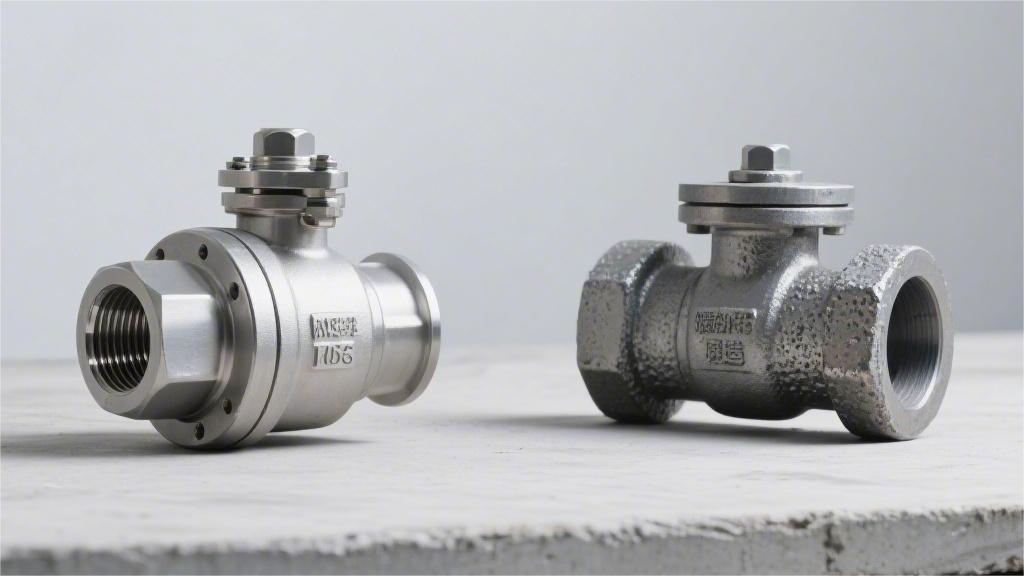
Forged steel side-entry ball valves are forged under high pressure, resulting in a dense internal structure without porosity, extremely high strength, the ability to withstand high pressures of Class 2500 (approximately 42 MPa) and above, and exceptional durability.
Cast steel ball valves are formed by pouring molten steel. They are prone to internal shrinkage cavities and generally have a pressure rating below Class 900, but they are suitable for large-diameter, low-cost manufacturing.
In practical selection and operation, if the pipeline pressure exceeds 10 MPa or the medium is flammable and explosive, forged steel valves must be selected to prevent leakage and rupture.
Strength
Forged side-entry ball valves (such as ASTM A105) undergo mechanical extrusion to reshape metal grains and form directional flow lines, resulting in an internal porosity of close to 0%.
Their standard yield strength reaches over 250 MPa, and tensile strength exceeds 485 MPa. Cast ball valves (such as ASTM A216 WCB) are formed by the solidification of liquid metal, with isotropic grains and a yield strength of approximately 205 MPa.
When subjected to system pressures exceeding 2000 psi or cryogenic environments of -196°C, forgings have no shrinkage cavities or micro-crack defects. The energy absorption value in the Charpy V-notch test is typically 20% to 30% higher than that of castings made of the same material.
Comparison of Mechanical Parameters
A material tensile testing machine stretches a standard circular metal specimen with a cross-sectional area of 0.2 square inches at a fixed rate. The test instrument accurately records the tensile force value when the material undergoes a 0.2% permanent plastic deformation. This data indicator is marked as the minimum yield strength on engineering physics drawings.
The minimum yield strength of forged carbon steel ASTM A105 at a normal temperature of 20°C is calibrated at 250 MPa. Under the same environment, the lower yield limit parameter of cast carbon steel ASTM A216 WCB is 205 MPa. ASME B16.34 sets entirely different valve body wall thickness calculation multipliers based on this 45 MPa physical stress difference.
After exceeding the yield point extremum, the metal material enters the plastic deformation zone until it is stretched and fractured. The highest tensile force recorded by the testing machine during this physical stage divided by the original cross-sectional area yields the tensile strength indicator. Carbon steels formed by the two manufacturing processes are subject to identical numerical specifications for their baseline tensile strength parameters.
| Carbon Steel Mechanical Test Items (ASTM A370) | Forged ASTM A105 | Cast ASTM A216 WCB |
|---|---|---|
| Minimum Yield Strength (0.2% offset) | ≥ 250 MPa (36,000 psi) | ≥ 205 MPa (30,000 psi) |
| Tensile Strength Limit Range | 485 – 655 MPa (70-95 ksi) | 485 – 655 MPa (70-95 ksi) |
| Axial Elongation (50mm Gauge Length) | ≥ 22% | ≥ 22% |
| Reduction of Area at Fracture | ≥ 30% | ≥ 35% |
The reduction of area reflects the lateral physical deformation capacity of a metal material before it is completely pulled apart. The displacement sensor of the universal testing machine shows that the radial shrinkage deformation of the A105 specimen before fracture is slightly smaller than that of WCB. The high-density directional microscopic metal flow lines forcibly constrain the physical slip of the material on the radial cross-section.
For pipeline fluid systems in -46°C cryogenic environments, the pipeline material grades are required by regulations to switch to ASTM A350 LF2 forgings and ASTM A352 LCC castings. Metal steels with low carbon content will undergo a complete physical ductile-to-brittle transition in sub-zero low-temperature environments. The Charpy V-notch pendulum impact test quantifies the fracture absorbed energy parameter of the material in extreme cold conditions.
A standard solid metal specimen measuring 10mm x 10mm x 55mm is placed in an industrial cooling bath and forcibly cooled to -46°C. A test hammer of the 300-joule magnitude physically strikes the back of the specimen notch at an initial velocity exceeding 5 meters per second. The test instrument panel digitally outputs the physical energy in joules consumed during the fracture of the specimen.
- The ASTM A350 LF2 Class 1 forging standard requires a minimum single-impact physical absorbed energy of 20 joules.
- In actual routine sampling, the energy absorption test values of LF2 specimens consistently remain in the 35 to 50 joules range.
- The minimum acceptance baseline value set by the ASTM A352 LCC casting specification is also 20 joules.
- Cast specimens are subject to random intervention by the internal microstructure, and the measured joule data mostly fluctuates around 22 to 30 joules.
When petrochemical pipeline systems transport highly corrosive industrial media, austenitic stainless steel is usually specified. Both ASTM A182 F316 forgings and ASTM A351 CF8M castings contain 16% to 18% chromium and 10% to 14% nickel metal elements.
The same austenitic metal matrix exhibits obvious physical differentiation in lattice density under the intervention of different forming physical pressures. The multi-million-ton physical compressive stress of the forging machine tool completely eliminates the dendritic segregation phenomenon caused by liquid cooling and solidification. Under the same geometric volume, F316 stainless steel exhibits higher macro-structural pressure-bearing rigidity than CF8M.
| Comparison of Stainless Steel Mechanical Indicators | Forged ASTM A182 F316 | Cast ASTM A351 CF8M |
|---|---|---|
| Normal Temp Baseline Yield Strength | ≥ 205 MPa (30,000 psi) | ≥ 205 MPa (30,000 psi) |
| Minimum Tensile Strength Requirement | ≥ 515 MPa (75,000 psi) | ≥ 485 MPa (70,000 psi) |
| Axial Elongation (50mm Gauge Length) | ≥ 30% | ≥ 30% |
| Factory Brinell Hardness Upper Limit | ≤ 187 HBW | No mandatory upper limit quantification spec |
The baseline tensile strength parameter of A182 F316 is forcibly pulled up by 30 MPa by industrial specifications. The high-pressure fluid inside the pipeline continuously exerts an outward radial physical thrust on the valve’s metal wall. According to Barlow’s wall thickness calculation formula, in a cylindrical pressure-bearing shell with consistent wall thickness data, an increase in tensile strength proportionally amplifies the overall burst safety pressure margin of the pipeline.
Metal hardness testing does not destroy the internal physical structure of the side-entry ball valve and is widely used for batch sampling on production lines. A standard indenter made of hard alloy is pressed into the metal surface under a vertical physical pressure of 3000 kilogram-force (kgf). An industrial measuring microscope accurately reads the diameter of the indentation on the metal surface and logarithmically converts it into a standard Brinell hardness value.
- The factory Brinell hardness inspection data for A105 forgings is usually evenly distributed between 137 and 187 HBW.
- The metal surface hardness readings of WCB castings that have undergone normalizing heat treatment fluctuate within 130 to 160 HBW.
- The surface physical hardness measurements of F316 and CF8M austenitic stainless steels are highly concentrated between 140 and 170 HBW.
- The NACE MR0175 specification mandates that the metal hardness used in sour gas fields must be lower than 22 HRC (approximately 237 HBW).
In the daily 90-degree opening and closing rotation test cycles of ball valve equipment, high-intensity physical friction occurs between the surface of the metal ball and the valve seat seal ring. The absolute surface hardness indicator of the pressure-bearing metal shell sets the physical service life of the equipment against fluid scouring and erosion.
Under controlled testing conditions at a normal temperature of 20°C, the elastic modulus values of forged and cast carbon steel both approach 200 GPa (gigapascals). When the operating temperature of the medium inside the chemical pipeline rises to a high-temperature limit of 425°C, the elastic modulus of carbon steel in both forms synchronously attenuates to around 165 GPa.
The physical input of high heat weakens the van der Waals bonding forces between atoms inside the metal, leading to a numerical decline in the overall physical rigidity of the material. The ASME B16.34 pressure-temperature rating baseline table sets 425°C as the maximum physical thermodynamic operating boundary for WCB and A105. After the material enters the high-temperature creep zone, it will undergo extremely slow permanent plastic physical elongation under constant pipeline fluid thrust.
The API 6D pipeline valve specification requires that the fully assembled ball valve must pass a hydrostatic shell physical test at 1.5 times the design pressure rating. For heavy-duty high-pressure pipeline valves of the Class 1500 pound class, the test water pressure is forcibly boosted to 5750 psi by a high-pressure plunger pump. This physical hydrostatic test is required to be maintained for more than 15 minutes to verify that the metal material has not undergone macroscopic plastic bulging deformation.
When a forging with a standard yield strength of 250 MPa is subjected to an internal test pressure of 5750 psi, the tangential stress distribution within the pipe wall exhibits a high degree of physical uniformity. For a casting with a 205 MPa baseline yield, under the same hydrostatic test environment, the local physical stress at the cross-section of the microstructure may approach 90% of the material’s yield limit value.
Impact of Internal Defects
The ASME B16.34 standard sets theoretical wall thickness parameters based on an ideal material state. In actual pipeline operations, the microscopic physical morphology inside the valve body material significantly interferes with the theoretical upper pressure limit. The volume change rates of solid metal and liquid metal during the forming stage exhibit completely different physical trajectories.
After liquid casting at 1500°C to 1600°C, WCB carbon steel needs to go through a solidification and cooling stage. When metal transforms from liquid to solid, its volume typically undergoes a physical shrinkage of 3% to 5%. There is a clear time difference in the cooling rate across different wall thickness areas of the side-entry ball valve.
The intersection of the flange neck or the valve seat cavity is usually thicker, and the cooling rate is slower than that of the outer surface. The internal molten metal solidifies last, and during this stage, it cannot obtain sufficient molten steel feeding. Microscopic shrinkage porosity or gas pores are then generated at the metal grain boundaries.
- Microscopic shrinkage: Occurs frequently in transition areas with abrupt changes in valve body wall thickness.
- Inclusions: Non-metallic oxide particles left over from the molten steel smelting stage.
- Hot tearing: Local strain at the end of solidification exceeds the absolute fracture limit of the material.
- Gas pores: Spherical cavities formed in the metal matrix by unexhausted deoxidizing gases.
The ASTM E446 specification provides reference radiographs for radiographic testing of steel castings with wall thicknesses below 2 inches (51 mm). Class A gas porosity or Class B sand inclusions under specific severity levels comply with industrial-grade acceptance standards. An absolutely dense state violates basic thermodynamic laws in the liquid casting process.
When the fluid flow rate in the pipe changes instantaneously, such as a sudden shutdown of a pump station or an emergency shut-off of a ball valve actuator, a water hammer effect is highly likely to occur in the pipeline. Transient pressure peaks will soar to 1.5 to over 2 times the normal operating pressure in an extremely short period.
Microscopic gas pores or shrinkage cavities on the cross-section break the physical uniformity of the stress distribution. The sharp edges of the micropores act as stress concentration sources on the pressure-bearing shell. The safety factor obtained through theoretical calculation experiences a cliff-like drop at local microscopic defects.
ASTM A105 or F316 forging materials completely bypass the volume shrinkage phenomenon caused by liquid solidification. Continuous casting steel billets are sent into a multi-ten-thousand-ton hydraulic press at an austenitizing temperature of about 1200°C. Massive mechanical compressive stress in three dimensions forces the solid metal to undergo deep plastic deformation.
- Forging ratio: Usually reaches 3:1 or above 4:1 to ensure the metal is fully compacted.
- Grain refinement: Forcibly shatters the original coarse dendrites and reorganizes them into fine equiaxed grains.
- Pore welding: Microscopic pores are physically closed and completely welded under high temperature and high pressure.
- Flow line distribution: The metal fiber structure completely conforms to the outer contour of the valve body, exhibiting a continuous distribution.
The fine porosity originally existing inside the steel billet is comprehensively compacted under a mold unit pressure of 400 MPa to 800 MPa. Physical extrusion completely eliminates the accommodating space for contained gases. The metal matrix density approaches the theoretical maximum density limit for that grade infinitely after forging is completed.
Continuous metal fiber flow lines increase the material’s mechanical load absorption rate in all three dimensions (X, Y, and Z). In sour gas field environments involving H2S covered by the NACE MR0175 specification, the extremely high-density forging matrix blocks the microscopic permeation paths of hydrogen atoms.
The probability of Hydrogen-Induced Cracking (HIC) or Sulfide Stress Cracking (SSC) is strongly positively correlated with the microscopic porosity inside the material. The forging process reduces the initial physical triggers for generating micro-cracks to an extremely low quantitative threshold.
Industrial Non-Destructive Testing (NDT) data objectively reflects the textural differences of the forming processes. When inspections are performed according to the Ultrasonic Testing (UT) specifications of ASME BPVC Section V, the acoustic feedback from the two materials is distinctly different.
- UT acoustic wave attenuation: The acoustic wave penetration rate inside forgings is extremely high, and the instrument’s bottom echo reflection is clear and sharp.
- Defect echoes: Dense, tiny forest-like echoes (grass-like waves) easily appear during the scanning of castings.
- RT radiographic films: There are almost no abnormal density areas on the X-ray films of forgings.
- Magnetic particle testing: There are very few magnetic flux leakage signals in surface and near-surface testing of forgings.
ASME B16.34 mandates that Special Class high-pressure valves must undergo 100% full-coverage radiographic or ultrasonic testing.
A single 12-inch x 16-inch industrial X-ray film can clearly record minute changes in material density. Faint dark spots deemed compliant under the MSS-SP-54 standard are frequently observed on casting films.
When the same X-rays penetrate a forged valve body, the film displays a highly uniform grayscale distribution. The absolute consistency of material density provides pipeline engineers with a high-precision fatigue life prediction model.
The ASTM A370 Charpy V-notch impact test validates the actual physical performance of the material’s internal density. In a deep-freeze environment of -46°C, a 10mm x 10mm standard specimen is physically struck by a heavy pendulum hammer.
The fracture impact energy absorbed by the LF2 forged carbon steel specimen usually stabilizes at 27 joules (J) to over 40 joules. Extremely tiny internal metal cavities drastically weaken the material’s mechanical ability to absorb deformation energy in the low-temperature brittle transition zone.
The impact data for LCC cast carbon steel specimens of the same physical dimensions have greater dispersion, and the specific impact energy value is significantly affected by the sampling location on the valve body. The pressure-bearing shell of a side-entry ball valve will face tens of thousands of high-pressure opening and closing cycles over its design life cycle.
A microscopic structure completely devoid of physical flaws blocks the initiation and propagation paths of fatigue cracks. In the million-cycle testing of the API 6D pipeline valve specification, the stability of the underlying physical state of the material sets the safety limits for the entire industrial fluid system.
Pressure-Bearing Wall Thickness Standards
The ASME B16.34 specification establishes mandatory geometric lower limits for metal shells used in industrial pipeline fluid control equipment. Appendix B of the standard contains detailed physical calculation tables for cylindrical pressure-bearing shells. Engineers extract specific minimum wall thickness baseline values for materials based on the system’s set maximum operating temperature and normal internal pipeline pressure.
In a testing environment at a normal temperature of 38°C (100°F), the maximum allowable working pressure for A105 forged carbon steel and WCB cast carbon steel in Class 150 pound pipelines is identically 285 psi. As the pipeline system load upgrades to the Class 1500 pound level, the static thrust of the internal fluid against the metal inner wall surges to 3705 psi.
Casting Quality Factor: For WCB cast shells that have not undergone 100% full-coverage radiographic testing, their ASME pressure-bearing calculation coefficient is forcibly reduced to 0.8.
A105 or F316 solid metal produced by the forging process defaults to the highest material factor of 1.0. When input into piping design software for 3D modeling, the physical coefficient difference between 0.8 and 1.0 results in the theoretical calculated wall thickness of WCB castings being at least 20% greater than that of A105 forgings of the same specification.
- 2-inch Class 1500 forged valve: The minimum wall thickness of the flange neck can be controlled at 11.1 mm (0.44 inches).
- Uninspected cast valve of the same specification: To compensate for the loss in the material factor, the minimum wall thickness must be increased to over 13.5 mm.
- Additional corrosion allowance: The API 6D pipeline valve specification typically requires an extra 3.2 mm (0.125 inches) carbon steel sacrificial layer superimposed on the theoretical wall thickness.
- Extreme high-pressure operating conditions: In Class 2500 systems bearing 6170 psi of operating pressure, the volume expansion rate of castings grows exponentially.
To withstand fluid bursting forces in ultra-high-pressure environments, all Class 2500 side-entry ball valves use high-yield-strength forged materials. Employing solid forged metal can control the overall physical deadweight of an 8-inch ultra-high-pressure valve to under 1.5 tons. If steel castings are used to achieve the same pressure-bearing tensile cross-sectional area, the total equipment weight will exceed 2.2 tons.
Heavy metal castings impose excessive static physical loads on the fundamental support frames of industrial pipelines. The API 610 centrifugal pump piping interface has extremely strict Newtonian mechanics limits for the flange bending moment and vertical stress connecting the valves. An overly heavy valve body can lead to excessive unilateral physical extrusion of the graphite spiral wound gasket at the flange connection.
When the pipeline diameter expands to 12 inches and above, the physical boundaries of the forming process begin to reversely constrain material selection. For a 24-inch Class 150 side-entry ball valve, the physical outer diameter of its internal metal ball exceeds 900 mm. Producing such a massive single-piece closed die forging requires the use of heavy hydraulic presses exceeding the 30,000-ton class.
Globally, the number of industrial forging plants with an extrusion capacity of over 30,000 tons is extremely rare. Once an ultra-large metal steel ingot is heated to 1200°C, it is extremely difficult to fully forge its center region in a short time even with a ten-thousand-ton hydraulic press. The geometric flexibility of the liquid casting process holds a clear statistical advantage for large-diameter low-to-medium-pressure fluid pipelines.
Large-diameter wall thickness compensation: The outer shell wall thickness of a 24-inch Class 300 cast valve usually reaches 38 mm (1.5 inches). This massive metal cross-sectional area is sufficient to offset the physical disadvantage of a lower 205 MPa yield strength.
Casting molds are not physically restricted by the plastic deformation resistance of solid metals, allowing for the one-time pouring of giant valve bodies featuring complex support ribs and non-standard flange bolt hole spacing. In Class 300 large-diameter main gas transmission pipelines with a pressure upper limit of 740 psi, over 85% of side-entry ball valves utilize WCB or LCC metal castings.
ASME B16.34 sets a depressurized operating trajectory for metal wall thickness in high-temperature environments based on temperature attenuation curves. When the fluid temperature in chemical plant pipelines climbs to 300°C, the absolute pressure-bearing capacity of A105 and WCB synchronously drops by about 18% compared to the 38°C normal temperature baseline.
- Radiographic testing upgrade: Elevating the non-destructive testing coverage rate of the casting to 100% allows its ASME material factor to rebound back to 1.0.
- Radiographic film cost: Conducting a panoramic X-ray exposure on a 16-inch cast valve body often costs over $2,000 in industrial films and manual labor hours.
- Forging inspection exemption advantage: The inherent high density of forged materials allows them to meet ASME’s full pressure-bearing calculation coefficient without requiring expensive volumetric radiographic testing.
Valve body pressure-bearing calculations must also superimpose complex physical tensile and bending stresses induced by external machinery. When a deep-sea oil and gas pipeline lay barge sinks the pipe to the 3000-meter seabed, the flange faces at both ends of the valve withstand massive axial physical pulling forces reaching hundreds of kilonewtons (kN).
Forged materials exhibit highly uniform tensile strength across the X, Y, and Z physical axes. Pipeline stress engineers write a 1.5x wall thickness allowance into the procurement specifications for subsea side-entry ball valves to resist external hydrostatic physical compression equivalent to 300 atmospheres in the deep sea.
Onshore Compressed Natural Gas (CNG) filling stations typically set the compressor outlet fluid pressure at around 4000 psi. A 2-inch high-pressure branch line subjected to high-frequency vibration conditions is equipped with F316 duplex steel or pure forged carbon steel valves featuring wall thicknesses exceeding 15 mm.
High-frequency mechanical vibration accelerates the physical tearing process of tiny pores at metal grain boundaries. The ASME B31.3 process piping code prohibits the use of uninspected thin-walled metal castings in fluid pipelines accompanied by severe pressure pulsations.
Pressure Capacity
According to the ASME B16.34 standard, the safe pressure-bearing capacity of cast valve bodies (containing 1.5%-3% microporosity) stays below Class 600 (1480 psi).
Crossing this boundary makes it easy for high-pressure fluids to trigger micro-leakage through the pores. Forged valve bodies undergo thousands of tons of mechanical stamping, dropping the porosity rate below 0.01%.
The continuous metal flow line structure enables them to stably carry high internal pressures from Class 900 to Class 2500 (2220-6170 psi).
In deepwater oil and gas API 6D pipelines such as in the Gulf of Mexico, using forged shells is standard practice to meet high-pressure leak prevention regulations.
Pressure Limits of Casting Porosity
When industrial-grade side-entry ball valves are cast using sand molds or investment casting, the initial temperature of the liquid metal typically exceeds 2750°F. Taking ASTM A216 WCB carbon steel as an example, the cooling phase where liquid turns to solid is accompanied by a violent physical phase transition.
The phase transition triggers a natural volumetric shrinkage of 4.5% to 7.2% in the metal. If there is a temperature gradient difference when the gating system replenishes the liquid metal, incompletely solidified areas will form physical cavities.
X-ray testing (RT) films show that standard industrial steel castings retain 1.5% to 3.0% microscopic porosity internally. The pore diameters are generally distributed between 0.1 mm and 2.5 mm.
Free-state microbubbles form a randomly arranged three-dimensional network of gaps within the valve body wall thickness. According to the wall thickness formula in ASME B16.34 Appendix B, designers must add an extra 15% to 20% thickness compensation allowance for castings.
Common physical gap morphologies found in flaw detection reports include:
- Microscopic shrinkage porosity: Tiny sponge-like holes distributed along the centerline of the wall thickness.
- Macroscopic shrinkage cavities: Volumetric cavities concentrated at the junction of the flange and the valve body.
- Gas slag inclusions: 0.5 mm silicate particles left over from the reaction between molten metal and the sand mold.
- Hot cracks: Network-like fine cracks produced when cooling stresses exceed the material’s yield limit.
Hydrostatic pressure exerted by fluid on the inner wall of the valve cavity seeks the path of least resistance for transmission. When the internal system pressure reaches 1480 psi under the Class 600 standard, fluid molecules begin to permeate into the surface microporosity.
Microporosity alters the original continuous stress conduction path of the metal. Finite Element Analysis (FEA) data shows that a spherical pore with a diameter of 1.2 mm will cause the local stress concentration factor at its edge to rise to 2.5 to 3.0 times.
Local stress amplification causes the material’s actual yield strength to reach its critical point prematurely. When the 1480 psi pipeline fluid pressure acts on a stress concentration area, the equivalent applied force instantly breaches the 3500 psi local destruction threshold.
The area surpassing the physical threshold undergoes micron-level plastic deformation, and originally independent pores connect under fluid pressure extrusion. Methane or high-pressure steam travels along the connected pore network, resulting in micro-leakage toward the outer surface of the valve body.
When performing a 1.5x hydrostatic pressure test on cast shells, the API 598 standard quantifies the following physical extremes:
- Class 150 test pressure 450 psi: No visible fluid weeping from pores.
- Class 300 test pressure 1125 psi: Micro-weeping may appear in areas with thinned wall thickness.
- Class 600 test pressure 2225 psi: Flaw detection ratings below ASTM E446 Level 3 are highly prone to penetrating leaks.
When North American chemical plants process sour media containing hydrogen sulfide (H2S), corrosive fluid is trapped inside the microporosity. The NACE MR0175 standard mandates strict hardness testing for castings.
The trapped fluid triggers electrochemical reactions inside the pore cavities, eroding 0.05 mm to 0.1 mm of the metal inner wall annually. A 1 mm pore expands to 1.2 mm after two years of operation, weakening the shell’s overall tensile strength.
Physical changes in temperature synchronously intervene with the pressure-bearing upper limits. In 400°F high-temperature pipelines, the allowable stress of ASTM A351 CF8M stainless steel castings drops from 20,000 psi at room temperature to 17,500 psi.
When the metal expands due to heat, the lattice structures surrounding internal pores undergo dislocation slips. The superimposed effect of high temperature accompanied by high pressure forces engineering parties to strictly limit relevant valves to operate within the physical boundaries of Class 600.
Balancing safety with material physical attributes, engineering projects set the following defense lines during selection:
- Maximum pressure extreme: Absolutely not to exceed 1480 psi at room temperature.
- Ultimate thickness ratio: The ratio of wall thickness to pipe diameter must be greater than 0.15.
- Inspection coverage: High-pressure critical zones require 100% radiographic and penetrant testing coverage.
- Service life depreciation: Design life is reduced by 30% in high-frequency pressure-pulsing pipelines.
Pipeline pressures in North American municipal water treatment systems universally remain between 150 psi and 250 psi. The fluid kinetic energy is insufficient to activate the stress concentration effects of microscopic pores, and the redundancy in material tensile strength covers transient shocks caused by water hammer phenomena.
Forging Density and Pressure Resistance
An ASTM A105 carbon steel round ingot is fed into an industrial heating furnace, and the temperature is steadily raised to 2200°F (1200°C). The metal softens under high temperatures but remains in a solid state throughout, completely eliminating the volume shrinkage rate generated during the liquid-to-solid transition.
Solid-state reshaping circumvents the generation of physical pores. The 2200°F steel ingot is fed onto the work table of a heavy hydraulic press, ready to endure extreme physical extrusion.
The 15,000-ton closed-die forging equipment applies downward mechanical shock, generating an instantaneous pressure of up to 80,000 psi inside the mold. The massive physical force forcibly compresses the atomic lattice inside the metal, closing latent microscopic cracks in the raw material.
- The raw material porosity rate is physically compressed from an initial 0.2% to below 0.005%.
- The forged part’s density extremely closely approximates the theoretical physical limit of 7.85 g/cm³.
- Ultrasonic testing (UT) confirms internal grain diameters are refined to between 15 and 30 microns.
Extreme mechanical compression forces the metal crystals to stretch and rearrange along the physical contours of the valve body mold. Under a metallurgical microscope, a continuous and unbroken grain flow can be clearly observed penetrating the entire side-entry valve body.
Continuous metal flow lines act like bound steel cables, significantly boosting the material’s ability to resist physical shearing and tension. In ASME Class 1500 piping systems, forged shells easily endure internal fluid pressures of 3705 psi thanks to their dense physical structure.
The directionality of metal flow lines alters the yield limits. Physical yield strength tested along the flow line direction is 18% to 25% higher than data perpendicular to the flow lines.
Deepwater oil and gas pipelines in the Gulf of Mexico are laid on the seabed 10,000 feet underwater. The exterior of the valve body is subjected to external hydrostatic pressure of up to 4400 psi, requiring the material to possess extremely high anti-extrusion yield strength.
Valve bodies forged with ASTM A182 F51 duplex stainless steel provide a physical yield baseline of 65,000 psi. Up to 1.25 inches of dense wall thickness resists 4400 psi of external deep-sea pressure while internally blocking 5000 psi of natural gas fluid.
- API 10000 specification: For bearing a working pressure of 10,000 psi, a 6-inch pipe diameter requires a wall thickness of 1.85 inches.
- API 15000 specification: For bearing a working pressure of 15,000 psi, a 6-inch pipe diameter requires a wall thickness of 2.45 inches.
- Extreme physical testing: In a 22,500 psi hydrostatic burst test, the deformation rate of forgings remained within 0.4%.
In high-pressure sour gas field pipelines in the Middle East, fluids contain hydrogen sulfide (H2S) gases at concentrations reaching 15%. The near-zero porosity structure produced by the forging process eliminates physical microcavities where corrosive hydrogen atoms could gather inside the metal.
Lacking microscopic pores to serve as retention points, high-pressure H2S gases cannot cause Hydrogen-Induced Cracking (HIC) inside the valve body wall. NACE TM0284 tests indicate that after F316L forged stainless steel is soaked in a sour solution for 96 hours, the Crack Sensitivity Ratio (CSR) remains at 0%.
Extremely low porosity cuts off the microscopic leakage paths for gases. A helium mass spectrometer leak detector, set at an ultra-high sensitivity of 10 to the negative 9th power mbar·L/s, is unable to detect free gas molecules penetrating forged wall thicknesses.
When water pumps in a pipeline abruptly stop or valves close rapidly, fluid columns traveling at 15 ft/sec cause water hammer. Violent transient pressure shock waves surge to 2500 psi in 0.1 seconds, physically slamming into the internal cross-sections of the valves.
The refined grain structure inside the forging rapidly absorbs and disperses this massive physical kinetic energy through micron-level elastic deformation. In a -50°F environment, during the Charpy V-notch impact test, ASTM A350 LF2 low-temperature forged steel absorbed 35 joules of impact energy.
- High-frequency pulse endurance: 2 million cycles alternating between 1000 psi and 3000 psi, with no fatigue crack initiation.
- Thermal shock adaptability: Dropping abruptly from 400°F to -50°F, yield strength data fluctuations are below 4%.
- Ultrasonic inspection echo: When shear waves traverse a 2-inch forged wall thickness, the acoustic energy attenuation rate is less than 1.2 dB.
The physical consistency of the forging process ensures highly uniform mechanical performance across all areas of the valve body. For a solid forged block weighing 500 lbs, the Rockwell hardness (HRC) deviation from the outer skin to the center profile is strictly controlled within 2 units.
Physical homogeneity eliminates latent stress weak points within the material. When calculating pipeline thicknesses for a Class 2500 high-pressure gas transmission station, the ASME B16.34 formula does not require engineers to reserve any millimeter-level compensation allowance for internal defects in forgings.
In the primary coolant loop of a nuclear power plant under the ASME Section III standard, cooling water runs at 600°F accompanied by a pressure of 2250 psi. The continuous grain flow lines of ASTM A182 F304L stainless steel forgings guarantee that borated radioactive water is fully physically confined inside the pipelines.
A deep manufacturing defect of 0.5 mm easily leads to crack propagation over decades of thermal cycling and high-pressure effects. The 15,000-ton forging press physically eliminates impurity gaps right at the manufacturing source, enabling the valve to achieve a design life of 40 years under 2250 psi of pressure.
Pressure-Bearing Data Comparison
The ASME B16.34 specification translates the physical density of metallic materials into specific pressure and temperature rating curves. On the 100°F ambient temperature baseline, ASTM A105 forged steel and A216 WCB cast steel exhibit different physical load-bearing limits.
For side-entry ball valves identically labeled as Class 600, the maximum allowable working pressure for WCB cast steel at room temperature tops out at 1480 psi. The dense flow line structure of A105 forgings permits engineering parties to push the pipeline design parameters up to 6170 psi corresponding to Class 2500.
| ASME Pressure Class Parameters | ASTM A216 WCB Cast Steel | ASTM A105 Forged Steel |
|---|---|---|
| Class 150 (100°F) | 285 psi | 285 psi |
| Class 600 (100°F) | 1480 psi | 1480 psi |
| Class 1500 (100°F) | Not recommended or requires major thickening | 3705 psi |
| Class 2500 (100°F) | Prohibited from use | 6170 psi |
The disparity in pressure-bearing values is physically quantified in the wall thickness calculation formulas of ASME Section VIII. To compensate for the 1.5% internal porosity created by cooling shrinkage, an additional 0.25 inches of casting compensation allowance must be added to the theoretical wall thickness of steel castings.
Forged valve bodies extruded by ten-thousand-ton hydraulic presses achieve a physical density of 7.85 g/cm³, entirely omitting the 0.25-inch compensation allowance. For a 4-inch pipe diameter Class 900 shell, a forging only needs a 0.88-inch wall thickness to bear 2220 psi.
To prevent porous connection leakage under a 2220 psi hydrostatic pressure, castings are forced to increase metal wall thickness at the same location to 1.13 inches. This physical stacking of wall thickness subsequently alters the overall weight of the valve and the pipeline support load.
- Class 150 Rated 285 psi: Forged wall thickness 0.35 inches, total weight 45 lbs.
- Class 150 Rated 285 psi: Cast wall thickness 0.45 inches, total weight 58 lbs.
- Class 600 Rated 1480 psi: Forged wall thickness 0.62 inches, total weight 110 lbs.
- Class 600 Rated 1480 psi: Cast wall thickness 0.82 inches, total weight 145 lbs.
High-temperature pipeline environments further amplify the quantifiable deviations in material yield strength. In a 400°F thermal oil system, the allowable stress for standard CF8M stainless steel castings drops from 20.0 ksi at room temperature down to 17.5 ksi.
F316 stainless steel forgings still maintain a high allowable stress of 19.4 ksi at 400°F. Sporting a 10.8% structural strength advantage, forged shells effectively suppress the creep elongation of the metal lattice under operating conditions combining high temperatures with 1480 psi of internal pressure.
| Operating Temperature Indicator | Stainless Steel Casting (CF8M) | Stainless Steel Forging (F316) |
|---|---|---|
| 100°F (Normal Temp) | 20.0 ksi | 20.0 ksi |
| 400°F (Medium Temp) | 17.5 ksi | 19.4 ksi |
| 800°F (High Temp) | 13.2 ksi | 16.2 ksi |
| 1000°F (Extreme Temp) | 10.5 ksi | 14.1 ksi |
The API 598 fluid hydrostatic test standard applies 1.5 times the design pressure to products fabricated by both processes. The chloride ion content in the test water is strictly controlled below 50 ppm to prevent free ions from masking minute physical cracks.
Targeting Class 900 pipelines, testing equipment injects hydraulic pressure up to 3350 psi into the shell interior and holds it for 300 seconds. Data from North American third-party laboratories shows that the initial micro-leakage rate for conventional steel castings at this pressure reaches 4.2%.
For forged steel valves of the same specifications participating in the 3350 psi test, internal porosity is lower than 0.01%, and the failure rate during the initial hydraulic test is a mere 0.05%. An 84-fold disparity in passing rates establishes the physical selection redline for deepwater platform procurement officers.
- Class 300 Hold Pressure: 1125 psi hydraulic pressure, mandatory duration 120 seconds.
- Class 900 Hold Pressure: 3350 psi hydraulic pressure, mandatory duration 300 seconds.
- Class 1500 Hold Pressure: 5575 psi hydraulic pressure, mandatory duration 300 seconds.
- Physical Passing Line: 0 drops/minute of liquid leakage on the external surface of the valve body.
Reciprocating compressor pipelines produce high-frequency pressure pulses at a frequency of 15 Hz. Internal pipeline fluid pressures oscillate violently between 800 psi and 1200 psi 15 times a second.
Continuous pressure wave bombardments strike 0.5 mm spherical slag inclusions inside the castings. After 2.5 million pressure cycles from 800 to 1200 psi, fatigue micro-cracks measuring 0.2 mm deep initiate at the stress concentration zones surrounding the inclusion edges.
The continuous grain boundaries formed by forging extrusion effectively absorb and disperse the 15 Hz mechanical oscillation energy. Running 10 million pressure cycles under identical parameters results in no physical distortion in the ultrasonic testing echoes inside the forgings.
| Cyclic Test Parameters | Cast Shell Performance | Forged Shell Performance |
|---|---|---|
| Pressure Fluctuation Range | 800 psi – 1200 psi | 800 psi – 1200 psi |
| Pulse Fluctuation Frequency | 15 Hz | 15 Hz |
| Micro-crack Appearance Point | ~2.5 million cycles | >10 million cycles, no abnormalities |
| Fatigue Failure Morphology | Cracks initiate at internal slag | Maintains original yield strength |
In Liquid Natural Gas (LNG) storage systems at -320°F (-196°C), extremely low temperatures cause metal impact toughness to plummet. For ASTM A352 LCC low-temperature cast steel at -50°F, the Charpy V-notch impact test can only provide 15 joules of absorbed energy.
Under identical environmental temperatures, the impact absorbed energy of ASTM A350 LF2 low-temperature forged steel reaches 27 joules. A physical toughness surplus of up to 80% prevents catastrophic brittle fractures from occurring in the pipelines under 1480 psi of deep-freeze high pressure.
- -320°F Impact Test Standard: Single-strike absorbed energy >20 joules.
- Helium Mass Spectrometer Leak Detection Upper Limit: Free gas <0.005 ml per minute.
- Casting Inspection Mandate: Radiographic testing (RT) 100% covers the wall thickness volume.
- Forging Inspection Routine Mandate: Execute surface ultrasonic testing (UT) according to ASTM A388.
The non-destructive inspection costs for high-pressure pipelines are redefined by physical density. For a Class 900 cast valve body, performing Level III radiographic penetration testing compliant with ASME codes costs about $850 for a single run.
For a forged valve body of equal volume, the continuous metal flow line structure eliminates the process of deep-layer porosity screening. By executing standard Ultrasonic and Magnetic Particle Testing (MT), the physical inspection cost per unit is drastically slashed to $120.
When conveying high-pressure sour pipelines with partial pressures of hydrogen sulfide exceeding 0.05 psi, NACE MR0175 regulations forcibly intervene. To prevent sulfide stress cracking, the Rockwell hardness of the metal interior contacting the medium is limited to a maximum of 22 HRC.
The hot forging process grants materials the physical conditions for uniform cooling; various cross-sections of a 1.5-inch wall thickness all maintain between 18 and 20 HRC. Cast steel components with uneven local cooling are prone to exhibiting 24 HRC physical hardening spots at the flange root, inducing microscopic tearing under high pressure.
Durability
Forged side-entry ball valves maintain a high degree of physical stability within the -196°C to 500°C range. Internal metal grains form continuous flow lines along the contour, and the Mean Time Between Failures (MTBF) can exceed 100,000 switching cycles.
Cast ball valves (such as ASTM A216 WCB) rely on the wall thickness allowance of the ASME B16.34 standard to resist corrosion, but when withstanding high-frequency pressure alternations above 2000 psi, internal microscopic gas pores shorten the metal’s fatigue life by 30% to 40%.
In highly sulfur-containing environments complying with the NACE MR0175 standard, the extremely high density of forged components makes their resistance to intergranular corrosion vastly superior to that of castings.
Long-Term Operating Life
In life cycle tests under the API 598 standard, forged side-entry ball valves utilizing ASTM A105 material usually exceed 100,000 fault-free operating cycles.
Under the exact same test environment, ASTM A216 WCB cast material ball valves bearing ASME Class 900 level pressures usually exhibit signs of metal fatigue after 50,000 to 60,000 cycles.
The stark difference in physical service cycles between the two stems from the alignment morphology of grains during the initial stages of metal forming. Tens of thousands of tons of forging pressure applied by massive hydraulic presses squeeze the internal grain size of solid metal down to an ASTM E112 standard Level 8 or even finer.
- There are no microscopic pores larger than 0.05 mm inside the metal.
- Material yield strength remains highly consistent across all three spatial dimensions.
- Zero plastic deformation occurs when enduring 2500 psi pressure alternations.
- Non-Destructive Testing (NDT) first-pass yield rate reaches 99.8%.
The casting process requires heating metal above 1500°C to melt it, and then pouring it into molds to cool and form. As liquid metal transitions to solid, an inevitable volumetric shrinkage of 1.5% to 2.5% occurs. The ASME B16.34 specification stipulates corresponding wall thickness additive values for this.
By relying on 3 mm to 5 mm of added physical wall thickness, cast ball valves obtain highly cost-effective service performance in low-pressure systems. In ASME Class 150 water treatment pipelines where operating pressure is below 285 psi, a thickened cast carbon steel shell is sufficient to resist fluid corrosion and provide a stable operating cycle of over 20 years.
When the working environment shifts to 3000 psi high-pressure gas injection lines in the North Sea oil fields, the microscopic state inside the metal dictates the valve body’s survival time. High-frequency pulse pressures continuously bombard the pressure-bearing shell of the valve body, and minute inclusions permissible under Level 2 Radiographic Testing (RT) standards evolve into stress concentration points.
- Micron-level stress tearing occurs around tiny inclusions.
- They highly easily develop into 0.1 mm visible cracks after 36 to 48 months.
- Local metal wall thickness undergoes abnormal thinning under fluid scouring.
- The risk of fatigue fracture rises exponentially over time.
Pipeline temperatures at LNG receiving terminals frequently toggle between ambient temperatures and -196°C. Forged ASTM A182 F316L stainless steel can still maintain a Charpy impact energy exceeding 40 joules under cryogenic conditions.
Cast versions of CF8M stainless steel, upon undergoing identical thermal shock, usually see impact absorbed energy drop below 25 joules. Operating data from LNG terminals in Texas, North America, indicates that after 5 years of weekly ultra-low-temperature loading and unloading cycles, intergranular separation phenomenon emerged inside some cast valve bodies.
| Material Type | Test Environment | Shell Attenuation Rate After 5 Yrs | Expected Replacement Cycle |
|---|---|---|---|
| ASTM A105 (Forged) | Sour Natural Gas (1500 psi) | < 0.2% | 15 – 20 Yrs |
| A216 WCB (Cast) | Sour Natural Gas (1500 psi) | 1.8% – 2.5% | 7 – 10 Yrs |
| A182 F316 (Forged) | Liquid Natural Gas (-196°C) | 0% (No grain boundary change) | 25 Yrs |
| A351 CF8M (Cast) | Liquid Natural Gas (-196°C) | 1.2% (Local microcracks) | 12 Yrs |
A thirty-year equipment maintenance database from a Houston refinery quantifies the time costs associated with the two forming processes during late-stage operations. For high-frequency opening/closing forged side-entry ball valves, the metal valve body shell can sustain a healthy status for over 85,000 hours, and maintenance work is confined to replacing non-metallic valve seats and O-rings.
When pipelines adopting cast valve bodies run up to roughly 40,000 hours, in addition to regular seal wear, the internal cavity of the valve body is normally accompanied by cavitation and scouring thinning on the metal surface. When internal pipeline flow velocities reach 15 meters per second, the scouring thinning speed on cast surfaces (initial roughness Ra 6.3 microns) is 1.8 times that of forged parts (Ra 3.2 microns).
- Forged valve bodies require no online welding repairs throughout their entire lifecycle.
- In highly sandy fluids, the annual inner wall wear rate of forged parts is below 0.03 mm.
- Cast parts in high-speed fluids necessitate ultrasonic thickness measurements every 5 years.
- The risk of Hydrogen-Induced Cracking (HIC) for cast valve bodies increases in acidic environments.
In automated control systems equipped with actuators, the rigidity of the valve body affects valve stem alignment. Under high-torque operations spanning 10 years, the dimensional tolerance variation in the forged stuffing box area does not surpass 0.02 mm, ensuring that VOC micro-leakage tests continuously comply with the ISO 15848-1 standard.
Large cast ball valves are constrained by the microscopic porosity inherent in their materials across the stuffing box region. After enduring tens of thousands of high-torque friction events, the hole diameter easily develops physical slop exceeding 0.1 mm. Mechanical clearances surpassing tolerance ranges cause graphite packings to lose pre-tightening force, necessitating re-machining of the stuffing box or even overall scrapping of the valve after 8 to 10 years of operation.
Temperature Alternation Fatigue
At Liquid Natural Gas (LNG) receiving terminals in North America, when a 25°C ambient temperature valve body is injected with -196°C liquid nitrogen for pre-cooling, the temperature drop rate reaches 150°C per minute.
Physical thermal expansion and contraction traits cause different wall thickness regions of the valve body to generate tensile loads exceeding 30,000 psi. Forged side-entry ball valves utilize ASTM A350 LF2 low-temperature carbon steel. After undergoing ten-thousand-ton mechanical rolling, its grain size achieves an ASTM E112 standard of Level 7 or above.
When subjected to thermal shocks of 150°C per minute, the fine, dense equiaxed grain structure evenly disperses extreme mechanical stresses into billions of grain boundary networks.
- Having experienced 2,000 extreme thermal cycles from 25°C to -196°C.
- The pressure-bearing shell showed no microscopic cracks longer than 0.05 mm.
- Helium leakage tests were maintained at the ISO 15848-1 Class B leakage rate.
- Charpy V-notch impact energy remains stably above 27 joules at -46°C.
When coping with drastic temperature steps, ASTM A352 LCC cast ball valves of the same diameter and pound class exhibit completely different service life degradation curves. The cooling speed of liquid metal in sand molds is restricted by wall thicknesses; the thickness difference between the valve body flange root and the middle cavity connection usually exceeds a factor of 2.
Disparities in cooling rates easily foster dendritic crystals and micron-level shrinkage pores inside castings. When the internal medium temperature scales from 200°C up to 450°C within 5 minutes, high-temperature steam or hot thermal oil rapidly heats up the surface layer metal on the valve body’s inner wall.
Bound by its thickness, the outer wall of the casting still remains in a relatively low-temperature state, immediately forming a transverse temperature gradient of up to 120°C between the inner and outer walls. Uneven thermal expansion generates intense shear forces, which rapidly accumulate and release along dendritic boundaries and micro-pores within the casting’s structure.
- Operating up to the 800th alternating cold/hot cycle node.
- Micron-level fatigue tearing originates at the edges of internal micro-pores.
- Crack propagation rates reach 0.08 mm per 100 cycles.
- Allowable thermal stress margins mandated by ASME BPVC drastically drop by 25%.
In delayed coking units at Gulf of Mexico refineries in North America, pipeline equipment frequently alternates between 500°C high-temperature oil/gas and normal temperature flush water. ASTM A182 F9 alloy steel ball valves produced via forging processes display extremely high physical toughness under 500°C operating conditions.
The thousands of tons of plastic deformation force applied during the forging-forming step compacts the internal structure of the metal, totally eradicating microscopic defects prone to triggering fatigue sources. In continuous testing over 36 months, featuring 4 cold-heat alternating cycles daily, the flatness deformation tolerance of the forged valve body flange sealing face was less than 0.02 mm.
After undergoing the same high-temperature water quenching thermal shocks, ASTM A217 C12 alloy steel cast material suffered from carbide precipitation and localized embrittlement phenomena at the grain boundaries. Phased Array Ultrasonic Testing (PAUT) reports in the 15th month revealed that thermal fatigue crack networks ranging from 1.5 to 3.0 mm deep appeared on the casting’s surface.
| Tested Material Model | Cyclic Temp Diff (ΔT) | Cycle Count | Penetrant Test (PT) Results | Geometric Dimension Deformation |
|---|---|---|---|---|
| Forged A182 F347 | 450°C | 5,000 cycles | No linear defect indications on surface | Trace deformation on sealing face < 0.01mm |
| Cast A351 CF8C | 450°C | 5,000 cycles | 1-2 fine crazing spots found | Sealing face warpage up to 0.08mm |
| Forged A350 LF3 | 200°C | 10,000 cycles | Crystal microstructure intact & undamaged | No obvious change in bolt hole dia tolerance |
| Cast A352 LC3 | 200°C | 10,000 cycles | Micro-cracks at localized thickness step zones | Bolt hole out-of-roundness 0.05mm |
Severe alternating temperatures not only test the outer wall of the valve body’s pressure-bearing shell but also apply continuous low-cycle fatigue loads to the side-entry ball valve’s flange bolt connection system. According to ASME PCC-1 bolting assembly guidelines, B7 or B8M high-strength bolts connecting the valve body and side cap undergo irreversible stress relaxation during thermal cycling.
Forged flange structures are extraordinarily dense, and their thermal expansion coefficients maintain perfect isotropy in radial and axial directions. After enduring 1000 alternating cycles from 200°C down to ambient temperature, forged flanges retain an 88% residual preload retention rate on the bolts.
Cast valve body flange structures exhibit density variances on a microscopic level, resulting in slight asymmetrical mechanical deformation when heated and expanded. These minute asymmetrical expansions cause massive losses in bolt preload during the cooling phase of the thermal cycle. After 1000 cycles, residual stress plummets to under 65%.
- Insufficient tightening force causes metal spiral wound gaskets to fail to rebound.
- Microscopic medium leakage of 0.5 ml per minute occurs at ambient temperatures.
- Maintenance teams must re-calibrate torque using hydraulic wrenches every 6 months.
- Thermal tightening maintenance cycles for forged valves extend to 24-36 months.
In the Steam Assisted Gravity Drainage (SAGD) pipelines for oil sand extraction in Alberta, Canada, wet steam hitting a peak of 350°C intermittently scours the valve bodies. During steam supply shutdowns, external pipeline temperatures plummet to -20°C freezing environments within 4 hours.
Under extreme alternating hot and cold shock tests, ultrasonic thickness gauges (UT) verified that forged A105N carbon steel valve bodies suffered no abnormal attenuation due to internal thermal fatigue cracking within a 5-year span. In API 598 high-pressure water sealing tests, post-thermal shock forged ball valves maintained a zero-leakage state at 1.5 times nominal pressure.
Constrained by the cooling rates of sand casting processes, cast WCC carbon steel valves used upstream on the exact same pipeline showed microscopic thermal stress concentration points in the valve seat insert groove areas. During the downtime maintenance cycle in the 4th year, fatigue derivative cracks exceeding 2 mm in length were detected at the root of the insert grooves in 15% of the cast valve bodies.
Fluid Scouring and Wear
In wellhead installations for shale gas extraction in North America, fluid injection velocities frequently break past 18 meters per second, entrained with quartz sand particles measuring 0.1 to 0.5 mm in diameter.
ASTM A105 forged carbon steel undergoes mechanical extrusion by a 50,000-ton hydraulic press during manufacturing. The surface layer metal undergoes severe plastic deformation, forming extremely high density. The initial inner wall surface roughness (Ra) of a forged side-entry ball valve can reach 3.2 microns without secondary machining.
Pipeline monitoring reports from the Permian Basin in Texas, USA, show that in natural gas extraction pipelines running at 25 m/s with a sand volume ratio of 2%, the annual wear thinning rate on the inner wall of forged carbon steel valve bodies is strictly controlled to under 0.04 mm.
ASTM A216 WCB material cast ball valves rely on liquid metal cooling and crystallizing naturally in sand molds. Micro-thermal exchange reactions between liquid metal and sand mold contact surfaces leave micro-porosity in the metal’s surface layer. Initial surface roughness typically falls between Ra 6.3 and 12.5 microns.
When fluid carrying abrasive particles flows past a rough cast surface at 15 m/s, micron-level turbulent vortices easily arise within the fluid boundary layer. Localized fluid kinetic energy spikes greatly increase the kinetic impact forces of solid particles against metal grain boundaries, driving the surface material spalling rate up by 1.5 to 2.2 times.
According to the API 598 hydrostatic scouring test database, when fluid containing 3% suspended solids continuously scours at a 2000 psi pressure differential for 10,000 hours, pit depths on the casting surface hit 1.2 mm. Localized physical wall thickness depletion is 1.8 times that of a forged component.
Beyond mechanical grinding by solid particles, sharp pressure drops prone to occurring in liquid pipelines trigger severe cavitation erosion phenomena. In 3000 psi high-pressure water injection pipelines operating in the North Sea oil fields, localized fluid hydrostatic pressure inside valve bodies frequently plummets momentarily below the saturated vapor pressure of 20°C water (0.34 psi).
Thousands of tiny bubbles burst and collapse near the surface of the cast metal, releasing micro-jets with an impact pressure exceeding 145,000 psi. The inherent microscopic shrinkage and porosity within the cast structure act as initiation points for cavitation cracks. The high-frequency jet impact can hollow out honeycomb-like pits up to 0.5 mm deep on the inner wall of the casting within 24 months.
The continuous and intact metal flow lines inside forged side-entry ball valves fully eliminate structural voids in the sub-surface. Facing the same 145,000 psi micro-jet bombardment, the dense forged surface will only experience exceptionally slight microscopic plastic deformation. Metal grains lock tightly together, preventing massive material spalling.
Slurry pipelines for oil sands extraction in Alberta, Canada, transport high-viscosity bitumen blended with heavy loads of quartz sand at 85°C. Intense mechanical cutting and fluid scouring jointly dictate mandatory equipment replacement schedules:
- Annual scouring depletion for forged A182 F51 duplex stainless steel is below 0.02 mm.
- Annual single-side thinning for cast A890 4A material at the same flow velocity hits 0.07 mm.
- Ultrasonic thickness (UT) census cycles for forged parts in high-speed slurry pipelines extend up to 60 months.
- Castings in equivalent abrasive pipelines require Radiographic Testing (RT) re-inspections every 18 months.
The contact interface between the valve body and internal non-metallic seat rings endures top-intensity throttling scouring loads during opening and closing actions. When the ball’s opening angle sits at 5 degrees, localized high-speed jets reaching 40 meters per second are generated at the slit, applying immense fluid shear stresses to the metal insert groove.
The forging process endows metal with extraordinary mechanical machining stability, allowing dimensional processing tolerances for the valve seat insert groove to be strictly kept within 0.015 mm. Extremely flush geometric assembly cuts off the path for high-speed fluids to bore behind the valve seat, maintaining the seal structure’s full physical integrity over more than 80,000 switching cycles.
Bound by cooling shrinkage rates, the bottom corners of valve seat insert grooves in cast valve bodies easily harbor exceptionally fine sand inclusion defects. When fluids cut through this area at 40 m/s, they scour out a 0.15 mm micro-gap within 36 months, leading the elastic O-rings to lose mechanical support.
In pipeline systems holding high-concentration sour media, fluid scouring and chemical corrosion produce fierce synergistic destruction effects on metal surfaces. While internally conveying natural gas mixed with 500 ppm of Hydrogen Sulfide (H2S), a frail iron sulfide passivation film forms on the inner wall of carbon steel valve bodies.
High-speed fluids rushing at 20 meters per second continuously strip off the superficial iron sulfide protective film. Highly dense forged surfaces can prompt uniform and rapid regeneration of the passivation film post-stripping. Conversely, rough cast surfaces produce micro-battery effects due to uneven protective film detachment, inducing accelerated propagation of localized pitting at a rate of 0.3 mm per year.

")