
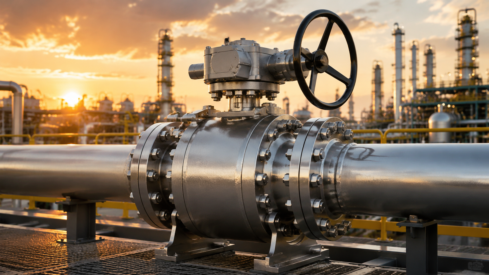
The seal utilizes a PEEK bi-directional valve seat resistant to high temperatures up to 260°C to ensure zero leakage;
The stem features an anti-blowout stepped design and is equipped with multi-stage O-rings to prevent leakage;
The surfaces of core components undergo 50-micron-thick Electroless Nickel Plating (ENP) or Inconel alloy weld overlay for corrosion resistance, which, combined with regular grease injection maintenance, can ensure the long-term safe operation of the pipeline.
Sealing System
Under Class 1500 (25.5 MPa) operating conditions, valves meeting the ISO 5208 Rate A standard must maintain no visible bubbles for 3 minutes during a full-pressure test.
Adopting Polyether Ether Ketone (PEEK) combined with a Double Isolation and Bleed (DIB) structure can maintain 50,000 opening and closing cycles in 200°C and 5% H2S media.
During selection, engineers equipping the valve with a combination of Anti-Explosive Decompression (AED) rubber and API 6FA fire-safe metal lip seals can reduce the unplanned downtime rate by 40%.
Materials & Temperature
The molecular chain of virgin Polytetrafluoroethylene (PTFE) remains stable in the range of -50°C to 200°C. Virgin PTFE will experience cold flow deformation under 10 MPa pressure; in industrial manufacturing, 15% to 25% of glass fiber or carbon powder is usually blended in for physical reinforcement.
Reinforced PTFE (RTFE) raises the material’s compressive yield threshold to 15 MPa. On offshore oil production platforms in the Gulf of Mexico, RTFE valve seats can withstand 10,000 continuous opening and closing cycles without plastic extrusion in 150°C crude oil media.
Polyamide (Nylon) provides higher mechanical tensile strength, with test values reaching 70-90 MPa. Nylon 12 has a water absorption rate of less than 0.1%, maintaining absolute dimensional stability over the long term in 120°C Class 900 (15.3 MPa) natural gas pipeline networks.
Polyether Ether Ketone (PEEK) can operate continuously at high temperatures of 260°C, with a tensile strength exceeding 100 MPa. In Class 1500 (25.5 MPa) high-pressure gas injection wells, PEEK material exhibits extremely high resistance to rapid gas decompression.
| Polymer Material Name | Tensile Strength (MPa) | Maximum Continuous Operating Temperature | Applicable Maximum Pressure Class |
|---|---|---|---|
| Virgin PTFE | 20 – 30 | 200°C | Class 600 (10.2 MPa) |
| Reinforced PTFE (RTFE) | 25 – 35 | 200°C | Class 900 (15.3 MPa) |
| Polyamide 12 (Nylon 12) | 70 – 90 | 120°C | Class 900 (15.3 MPa) |
| Polyether Ether Ketone (PEEK) | 100 – 110 | 260°C | Class 2500 (42.5 MPa) |
| Polychlorotrifluoroethylene (PCTFE) | 30 – 40 | 120°C (Common for cryogenic) | Class 1500 (25.5 MPa) |
Liquefied Natural Gas (LNG) receiving terminals in Qatar handle ultra-low temperature fluids at -162°C. Ordinary polymer materials become brittle in extreme cold; Polychlorotrifluoroethylene (PCTFE/Kel-F) is widely applied because it still possesses a compressive strength of 35 MPa at -196°C.
When fluids contain quartz sand or pipeline iron oxide scale, the surfaces of polymer soft materials will be rapidly scratched. The system structure shifts to metal-to-metal physical contact, and a hardened layer is applied to the surface through the High-Velocity Oxygen Fuel (HVOF) thermal spray process.
Tungsten Carbide (WC) particles impact the ball and seat surfaces at a speed of 800 meters/second, forming a dense coating with a thickness of 0.15 mm to 0.3 mm. The surface Rockwell hardness reaches 70-75 HRC, capable of resisting severe abrasive wear in Class 2500 slurry pipelines.
Chromium Carbide (Cr3C2) coatings maintain physical and chemical stability in oxidizing environments up to 815°C. In high-temperature delayed coking units, a 0.2 mm thick coating prevents the metal galling of 316 stainless steel balls and seats during thermal expansion.
| Metal Hardening Coating | Typical Spraying Process | Surface Hardness | Maximum Operating Temperature |
|---|---|---|---|
| Tungsten Carbide | HVOF (High-Velocity Oxygen Fuel) | 70 – 75 HRC | 400°C |
| Chromium Carbide | HVOF (High-Velocity Oxygen Fuel) | 65 – 70 HRC | 815°C |
| Stellite 6 | PTA (Plasma Transferred Arc) | 40 – 45 HRC | 600°C |
| Electroless Nickel Plating (ENP) | Chemical Deposition | 50 – 55 HRC | 300°C |
The static gap between the metal seat ring and the valve body is sealed using elastomer O-rings. The Norwegian Norsok M-710 specification outlines testing procedures for the explosive decompression resistance of rubber materials in high-pressure CO2 or H2S environments.
Fluoroelastomer (FKM/Viton) provides chemical corrosion resistance up to 200°C. Standard 75 Shore A FKM will blister and rupture under a 10 MPa pressure drop; Anti-Explosive Decompression (AED) grade FKM increases the hardness to 90 Shore A to resist volume expansion.
The lower working temperature limit of Hydrogenated Nitrile Butadiene Rubber (HNBR) reaches -40°C, while also possessing the physical properties to resist sour gas (H2S) attack. Winter pipelines in Alberta, Canada use HNBR O-rings paired with PTFE backup rings to prevent extrusion damage under 15 MPa pressure.
Perfluoroelastomer (FFKM/Kalrez) can withstand highly aggressive amine desulfurization solvents and temperatures up to 327°C. Its procurement cost is 50 times that of conventional FKM, and it is usually only deployed in offshore sour gas reinjection manifolds.
When the ambient temperature breaches the 327°C upper limit or falls below the -50°C lower limit, polymer elastomers completely lose their resilience. Elgiloy alloy springs encased in Inconel 718 U-shaped jackets become the alternative, maintaining a radial contact load of 25 N/mm against the valve body sidewall.
- -196°C to -50°C: PCTFE primary seat equipped with Inconel 718 metal spring-energized seals
- -50°C to 120°C: Nylon 12 primary seat equipped with HNBR 90 Shore A elastomer O-rings
- 120°C to 200°C: RTFE primary seat equipped with AED grade FKM 90 Shore A elastomer O-rings
- 200°C to 260°C: PEEK primary seat equipped with FFKM (Kalrez) elastomer O-rings
- 260°C to 400°C: Tungsten carbide coated metal seat equipped with flexible graphite and Elgiloy metal lip seals
The NACE MR0175/ISO 15156 specification restricts the metallurgical parameters of metal pressure-bearing components in sour environments. Valve bodies forged from ASTM A350 LF2 carbon steel are mandatorily required to have a Rockwell hardness controlled below 22 HRC to prevent sulfide stress cracking.
Subsea manifolds at a depth of 3000 meters withstand external seawater hydrostatic pressure up to 30 MPa. The internal PEEK seats and the external Inconel 625 weld overlay of the valve body form a double physical barrier, isolating the internal corrosive fluid from the 4°C deep-sea environment.
The stuffing box in the stem area utilizes molded expanded graphite rings. The physical density of the graphite rings is compressed to 1.6 g/cm³, and mechanical stress is applied via a stainless steel packing gland to seal Volatile Organic Compound (VOC) fugitive emissions below 100 ppm.
Live-loaded Belleville springs are installed in series on the packing gland bolts to compensate for the microscopic volumetric shrinkage of the graphite during thermal cycling. Four pairs of 17-7 PH stainless steel spring sets continuously apply a vertical compressive stress of 15 MPa to the graphite packing assembly.
Pressure Relief && Isolation
In a 24-inch Class 900 pipeline in the Permian Basin, Texas, a 1°C temperature rise causes liquid propane pressure to surge by 7.5 bar. The API 6D specification mandates that the cavity pressure of pipeline valves must absolutely not exceed 1.33 times the design pressure. An unrelieved internal pressure of 30 MPa would cause a 0.4 mm microscopic geometric deformation of the 316L stainless steel ball and crush the 5 mm thick PTFE seal rings.
The SPE (Single Piston Effect) seat utilizes the fluid pressure differential across a 15 square millimeter cross-sectional area to generate a 4000 N horizontal displacement thrust that pushes the metal base toward the ball. When the cavity pressure exceeds the upstream pipeline pressure by 1.5 to 3 MPa, the outward expansion force of 10 liters of trapped liquid will overcome the 1200 N preload of the Inconel X-750 wave spring. The seat is pushed 0.2 mm away from the ball surface, discharging the overloaded 3 MPa liquid in reverse into the upstream pipeline network.
Side-entry ball valves equipped with two symmetrical SPE seats physically constitute a Double Block and Bleed (DBB) structure. API 6D defines this as an independent piece of equipment capable of simultaneously blocking high-pressure fluid at both ends while possessing the ability to bleed the cavity.
- The upstream SPE seat bears 15 MPa of pressure, generating an 8000 N initial sealing thrust.
- The downstream SPE seat synchronously blocks a 5 MPa backpressure reverse flow.
- After the bottom bleed valve is opened, 12 liters of residual media in the cavity are drained within 30 seconds.
- When the internal fluid thermally expands to 20 MPa, it automatically generates a physical release to the low-pressure side.
Natural gas trunklines transporting high concentrations of H2S in Alberta, Canada do not allow fluids to automatically flow back into the pipeline at specific nodes. Double Piston Effect (DPE) seats feature an internal geometric design that increases the external force-bearing area by 20%. Whether it is 15 MPa pipeline pressure from upstream or 10 MPa of abnormal pressure accumulating inside the cavity, the fluid physical thrust will generate a 25 kN net thrust pointing toward the center of the ball.
When both ends of the valve body are equipped with DPE seats, the equipment meets the mechanical classification of Double Isolation and Bleed (DIB-1). If the upstream Nylon seat surface is scratched by 0.1 mm of quartz sand causing a micro-leak of 500 ml/min, the cavity pressure will gradually rise to 15 MPa, matching the pipeline. The downstream DPE seat utilizes the 15 MPa cavity pressure to generate a contact stress of up to 30 kN, pressing tightly against the ball surface to form a second physical barrier. Operators must manually release the compressed gas within the 50-liter volume by opening the external needle vent valve.
The hybrid arrangement combining one SPE seat and one DPE seat is defined as the DIB-2 physical structure. The SPE component is installed on the upstream side to ensure automatic pressure relief to the 12 MPa main pipeline when internal pressure reaches 1.33 times the rated value. The DPE component is deployed on the downstream side to maintain an absolute mechanical isolation interface under a 20 MPa bi-directional fluid impact. In the 36-inch natural gas gathering manifold of the North Sea oilfield, this asymmetric arrangement handles the physical blocking task of 5 million cubic meters of gas daily.
Due to the lack of an internal self-relieving physical channel, the closed cavity of the DIB-1 structure is highly susceptible to metal shell rupture in liquid media applications. The ASME B16.34 specification mandates the addition of physical drilling on the exterior of the ASTM A105 carbon steel forged valve body and the installation of a safety relief valve. The 1/2-inch NPT threaded relief valve is pre-loaded with an internal spring, calibrated to pop open instantaneously at the physical threshold of 25.5 MPa. The discharged high-pressure liquid is routed through a 3/8-inch 316SS stainless steel impulse line into the closed flare system, intercepting 99.9% of fugitive methane emissions.
The 1-inch manual bleed valve installed at the very bottom of the valve body bears the dual tasks of state diagnosis and physical isolation verification. Maintenance technicians must fully open this needle valve before entering the downstream 24-inch pipeline for gas cutting operations.
- Discharges 5 liters of residual liquid naphtha per minute.
- The internal digital pressure gauge drops from 10 MPa to 0 MPa within 45 seconds.
- Continuous fluid dripping at the observation port indicates a 0.05 mm physical wear on the upstream 8-inch valve seat.
- Maintaining zero droplets during a 10-minute observation period is the physical prerequisite for issuing a safe work permit.
24 high-strength cylindrical coil springs provide a total horizontal preload of 12,000 N within the valve body slots. The constant mechanical thrust ensures that even at 0 MPa pipeline pressure, the PEEK sealing surface maintains a contact specific pressure of 5 MPa with the ball. The physical friction generated by the spring preload requires the pneumatic actuator to output a starting torque of 15,000 Nm to overcome static friction and rotate the ball 90 degrees.
When a 0.5 mm deep mechanical groove appears on the nickel-plated surface of the ball causing isolation failure, the external high-pressure grease injection system intervenes for physical repair. Technicians use a 10,000 psi hydraulic grease pump to inject fully synthetic Polyalphaolefin (PAO) sealant with a viscosity of 2000 cSt into the seat channel. The sealant passes through a 1/4-inch check valve and fills the microscopic voids around the damaged nylon insert. This temporary hydraulic sealing band, which is only 0.1 mm thick, reconstitutes the isolation capability of the DBB, maintaining a zero-leakage state for 72 hours under 15 MPa pressure.
Manufacturing plants rely on the API 598 hydrostatic testing procedure to verify the physical isolation data of DBB and DIB. The finished 12-inch valve is injected with room temperature water and pressurized to 1.5 times the design pressure (22.5 MPa). The cavity bleed port is kept physically open, enduring a 5-minute high-pressure hold. A third-party inspector visually confirms no water droplets seeping from the bleed port, thereby issuing a paper inspection report certifying the physical blocking qualification of the upstream and downstream SPE seats.
For gas transmission networks, the ISO 5208 specification introduces a low-pressure pneumatic physical tightness test using 0.6 MPa nitrogen. The leakage rate of soft-seated DIB-2 valves is mandatorily locked at the Rate A level. The test gas is introduced via a conduit into a 100 ml graduated cylinder inverted in a water tank. Recording zero bubbles in the cylinder during the 120-second physical timing cycle proves that the concentricity deviation of the DPE seat is controlled within a 0.02 mm tolerance range.
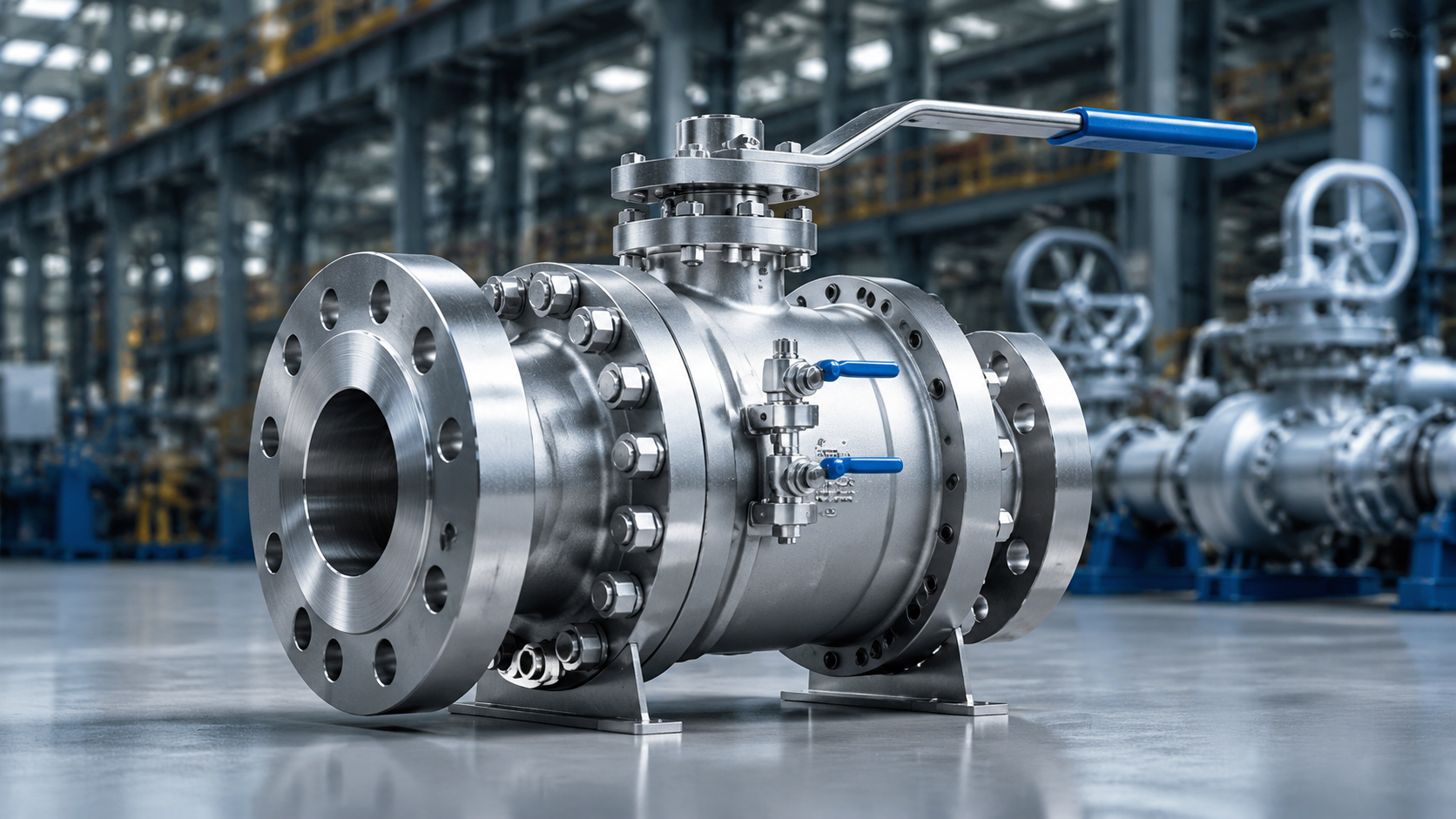
Stem Design
Adopting a bottom-entry anti-blowout structure paired with 17-4PH or Inconel 718 materials, the tensile strength can exceed 1000 MPa, capable of withstanding system pressure differentials of up to 420 bar in Class 2500 pipelines and operational torques of tens of thousands of Newton-meters (N·m).
In ISO 15848-1 standard testing, a combination of O-rings with Belleville spring compensation and API 622 graphite packing can stably control fugitive emissions below 50 ppmv (Class AH) within 100,000 on-off cycles, directly reducing overall fugitive emissions of the pipeline.
Anti-Blowout Design
When the piping system pressure reaches Class 1500 (approximately 250 bar), the vertical upward thrust exerted by the fluid on the bottom of the valve stem can reach tens of thousands of Newtons. A standard straight stem relies solely on the friction of external gland bolts for fixation; once the bolts loosen due to pipeline mechanical vibration, internal high pressure will instantly eject the metal stem.
Engineers machine a solid metal collar at the lower end of the component with a diameter 15% to 25% larger than the bore hole. Assemblers first place the transmission stem inside the valve body cavity, and then thread it upwards through the bearing hole at the top of the valve body. The natural gas or crude oil pressure in the pipe cavity acts on the bottom cross-section of the metal collar, generating a constant upward thrust.
At a system pressure of 100 bar, a bottom flat surface with a diameter of 50 mm will endure an upward lifting force of approximately 19,600 Newtons. The higher the pipeline pressure, the greater the thrust, and the tighter the collar is pressed against the internal shoulder of the valve body. A thrust washer with a thickness of 2 mm to 4 mm is placed between the collar and the metal shoulder of the valve body.
The washer is typically made of glass fiber-filled PTFE or PEEK polymer with higher compressive strength. The polymer washer maintains an extremely low friction coefficient of 0.05 even when subjected to physical extrusion up to 150 MPa. When operators remove the external gland bolts to replace the packing while the pipeline is pressurized, the internal fluid continues to push against the bottom metal collar.
Under high pressure, the thrust washer is fully compacted, forming a temporary mechanical backseat. The effectiveness of the bottom-entry backseat’s physical mechanism depends on the precise fit of several machining dimensions:
- The single-sided overlap between the collar’s outer diameter and the valve body’s bore hole is no less than 3.5 mm.
- The transition fillet radius of the shoulder is controlled at 0.8 to 1.2 mm to prevent stress concentration.
- The inner and outer diameter tolerances of the thrust washer are maintained within +0.15 mm.
- The surface roughness Ra of the metal collar must be less than 0.4 microns.
The collar portion and the main body are integrally formed by CNC lathe cutting from the same metal bar stock. When using ASTM A564 Type 630 material, the continuity of the overall metal lattice structure ensures that the collar position can withstand shear stresses exceeding 1040 MPa. If welding or pinning is used to secure the bottom collar, fatigue fractures are highly prone to occur after experiencing 10,000 pressure pulses.
When the water hammer effect occurs in a pipeline, transient pressure peaks will surge to 2.5 times the design pressure within 0.2 seconds. The metal shoulder of the bottom-entry structure transmits the severe mechanical impact force to the carbon steel valve body shell, which is over 50 mm thick. The external gland and retaining bolts bear absolutely no medium thrust from inside the pipeline.
When ambient temperatures spike from -46°C extreme cold to 150°C, there is a discrepancy in the thermal expansion rates of different materials. The thermal expansion coefficient of 17-4PH stainless steel is 10.8 µm/m·°C, whereas the PEEK thrust washer has a high expansion coefficient of 47 µm/m·°C. The design reserves an axial expansion clearance of 0.2 mm for the washer to prevent metal components from jamming due to drastic temperature changes.
According to the ASME B16.34 standard, the anti-blowout structure must pass a rigorous fluid hydrostatic testing process before leaving the factory:
- Inject clean water at 1.5 times the rated pressure into the valve cavity (Class 600 test pressure is 150 bar).
- Completely loosen all packing gland nuts at the top.
- Maintain the test pressure for more than 3 minutes.
- Use precision leak detectors to confirm that the gap leakage is zero.
- After depressurization, measure the permanent plastic deformation at the collar, which must not exceed 0.05 mm.
If a two-piece top-entry structure relies on a circlip for external restriction, the circlip groove reduces the effective load-bearing cross-sectional area of the metal by 30%. Under the long-term application of 300 N·m operating torque, micro-cracks will develop at the groove. Once the medium pressure breaches the internal packing, the circlip will suffer shear failure instantaneously.
As the pipeline diameter expands from 10 inches to 36 inches, the ball weight and medium thrust increase geometrically, and the cross-sectional diameter also increases from 40 mm to 120 mm. For a component with a diameter of 120 mm, the thickness of the bottom collar must reach at least 18 mm. The abundant metal cross-section is used to resist an upward medium lifting force of over 500 tons.
The massive medium thrust exponentially increases the sliding friction between the collar and the washer. In order not to exceed the maximum output limit of the pneumatic actuator (e.g., 25,000 N·m), the pressure-bearing area of the collar is precisely calculated to just meet the minimum cross-section requirements for material shear strength in the ASME specification.
Engineers balance anti-blowout safety and daily operating torque by adjusting specific physical parameters:
- Optimize the thickness of the thrust washer, not exceeding 15% of the total axial clearance.
- Blend 10% carbon fiber into the PEEK washer to improve high-temperature creep resistance.
- Change the outer edge angle of the bottom collar from a 90-degree right angle to a 15-degree chamfered design.
- Increase the thickness of the electroless nickel plating on the contact surface to 75 microns to reduce frictional work.
The bottom assembly topology utilizes fluid pressure to transform passive defense into active mechanical sealing. As long as there is a positive pressure differential of over 0.5 bar inside the pipeline, the physical barrier formed by the metal collar and the thrust washer continues to exert a blocking effect. The physical wear, loosening, or complete removal of external components absolutely does not alter the internal residing state under high-pressure lifting.
Low Fugitive Emission Control
The test uses a mass spectrometer to charge the pipe cavity with 97% purity helium, strictly detecting external trace gas escape. The Class AH level requires the leakage rate to be controlled within 5 x 10^-8 cubic centimeters per second at room temperature.
All the mechanical structures meeting the aforementioned quantitative standards are located within the stuffing box between the transmission stem and the outer shell. The depth dimension of the stuffing box is typically designed to be 1.5 to 2 times the internal metal stem diameter. Multiple independent sealing elements assembled internally are arranged in a stacked, in-series manner to prevent internal high-pressure fluid from diffusing outwards along the metal clearances.
The first physical barrier is an elastomer O-ring installed in the bottom metal groove. In systems containing carbon dioxide or high-pressure natural gas, ordinary rubber is extremely prone to Anti-Explosive Decompression (AED) damage. Fluoroelastomer (FKM) or Hydrogenated Nitrile Butadiene Rubber (HNBR) compliant with the NACE TM0297 test standard forms the initial blocking layer at the lowest level.
The machining dimensional tolerance of the O-ring groove is strictly limited to within +0.05 mm. The single-sided clearance between the transmission stem and the bottom metal retaining ring is set at 0.1 mm to 0.15 mm. The tiny physical clearance prevents the polymer material from undergoing physical extrusion deformation when enduring a 250 bar system pressure differential.
When encountering highly chemically corrosive media with high concentrations of H2S, a PTFE (Polytetrafluoroethylene) lip seal replaces the O-ring as the primary seal layer. PTFE material incorporated with 15% glass fiber maintains ample toughness even at low temperatures of -46°C.
Configured above the primary seal layer is a graphite packing assembly addressing fire safety (API 607 specification). Flexible graphite with a purity of 99% not only withstands high temperatures up to 450°C but also possesses an extremely low stress relaxation rate of under 5%. At room temperature, the heavy graphite packing is responsible for blocking trace permeated gases that slip past the bottom O-ring.
The graphite assembly is formed by pressing and stacking alternating layers of ring structures with different physical structures and densities:
- High-density braided graphite end rings are placed at the top and bottom, with a material density of 1.4 to 1.6 g/cm³.
- 3 to 4 low-density die-formed flexible graphite rings are sandwiched in the middle, with a material density of 1.1 to 1.3 g/cm³.
- The end rings contain built-in Inconel 625 alloy wire mesh to prevent internal soft graphite from washing out under 50 MPa physical extrusion.
- The cuts of each packing ring layer are staggered by 90 degrees during factory installation, blocking the straight-line escape path for gases.
The upper metal gland exerts physical thrust downwards from the top, causing uniform radial expansion of the internal graphite rings. Operators use a precision torque wrench to set the preload of the gland bolts to 25 N·m to 60 N·m. After 1000 mechanical open-close operations, the graphite material undergoes physical volumetric compression, and the initial compression force typically decays by 15% to 20%.
The external mechanical device that eliminates the decay of compression force is Belleville springs. Multiple disc springs made of 17-7PH stainless steel are installed in series above the gland bolts. During installation, the spring set is compressed to 75% of its total mechanical stroke, reserving a massive amount of physical deformation potential energy.
When the graphite packing below loses 0.1 mm in height due to physical wear, the compressed Belleville springs will automatically extend downwards. The released mechanical energy continuously pushes the bottom gland, maintaining a constant gasket specific pressure of over 5 MPa. This normalized automatic compression force compensation enables the component to pass the 100,000 mechanical cycle test required by API 624 in a maintenance-free state.
| Test Cycle Class | Number of Cycles | Leakage Rate Limit (Helium Medium) | Allowed Maximum Gland Bolt Adjustments |
|---|---|---|---|
| CO1 | 205 | Class AH (Strictly Controlled) | 1 Time |
| CO2 | 1500 | Class BH (Standard Requirement) | 2 Times |
| CO3 | 2500 | Class CH (Conventional Pipeline) | 3 Times |
The surface roughness data (Ra) of the metal dictates the volumetric wear rate of the polymer packing. In the specific area where the transmission stem makes frictional contact with the seals, the Ra value is polished with high precision to the 0.4 µm to 0.8 µm range. The Ra value of the internal metal bore wall of the stuffing box is machined to 1.6 µm to 3.2 µm.
The rougher outer wall texture firmly grips the outer ring of the graphite packing, while the smoother inner wall allows the transmission stem to rotate smoothly with an extremely low friction coefficient. Drastic fluctuations in ambient temperature alter the internal fit clearances of different metal components. In ultra-low temperature LNG pipelines at -196°C, the physical shrinkage rate of the carbon steel shell is far greater than that of the graphite packing.
Engineering specifications mandatorily require the introduction of specific iron-nickel alloy bushings with an expansion coefficient of only 0.0001/°C in cryogenic valves. The absolute outer diameter size of the stem dictates the numerical setting specifications for the anti-extrusion clearance:
- When the stem diameter is less than 25 mm, the single-sided physical clearance between the gland and the stem body does not exceed 0.2 mm.
- When the stem diameter is between 25 mm and 50 mm, the fit clearance is strictly limited to within 0.3 mm.
- For large-diameter components with a stem diameter greater than 50 mm, the clearance upper limit is uniformly set at 0.4 mm.
- The smaller the mechanical assembly clearance, the lower the probability of flexible graphite material being extruded into the metal gap under high pressure differentials.
When calculating the output torque of the pneumatic actuator, engineering software presets the packing friction coefficient at 0.15 to 0.20. An API 622 certified assembly subjected to a 40 MPa downward thrust will add an additional frictional resistance torque of approximately 120 N·m to one side of the transmission stem.
The test standard API 624 requires substituting 97% purity methane gas for helium to conduct thermodynamic crossover cycling. The assembly must undergo 3 complete heating and cooling test cycles between room temperature and 260°C. During this period, 310 pressurized mechanical openings and closings are performed. Using a Flame Ionization Detector (FID) probe taking samples 1 centimeter from the gland, the absolute value of methane concentration must not exceed 100 ppmv.
Materials & Anti-Wear
When pipeline operators open a 36-inch, Class 900 side-entry ball valve, the pneumatic actuator outputs a massive rotational torque of up to 15,000 N·m. The physical shear stress exerted on the cylindrical metal transmission shaft is extreme.
Conventional ASTM A182 F316 austenitic stainless steel has a yield strength of 205 MPa. Under a torque load exceeding 8,000 N·m, an 80 mm diameter 316 stainless steel stem will suffer an irreversible plastic torsional deformation of over 0.5 degrees.
Engineers select precipitation-hardening stainless steel ASTM A564 Type 630 (17-4PH) as the foundational base material. Following the H1150 heat treatment process, the yield strength of 17-4PH is elevated to 1050 MPa, enabling it to withstand a 20,000 N·m mechanical torque test.
The NACE MR0175 specification mandatorily stipulates physical standards for the environmental cracking resistance of metals in high-sulfur (H2S) natural gas pipeline systems.
When the H2S partial pressure within the pipeline network exceeds 0.05 psi, 17-4PH metal is highly susceptible to Sulfide Stress Cracking (SSC) due to hydrogen atom permeation. Sour gas field engineering projects in the Permian Basin of North America typically specify the use of Inconel 718 nickel-based alloy.
Inconel 718 contains 50% to 55% nickel and 17% to 21% chromium elements. In the temperature range from room temperature to 150°C, Inconel 718 maintains a high yield strength of 1200 MPa and is completely immune to wet hydrogen sulfide environmental attack at concentrations up to 150,000 ppmv.
The robust metal base provides sufficient torsional strength, but surface physical tribological characteristics determine the long-term survival rate of the external polymer seals. Intensive relative sliding friction occurs between the metal outer wall and the PTFE packing under system pressure differentials of up to 250 bar.
Machining lathes strictly grind the surface roughness parameter (Ra) of the metal outer wall to the 0.4 µm to 0.8 µm range. Microscopic metal protrusions with an Ra value exceeding 1.2 µm will cut away 0.05 mm of material from the surface of the PTFE seal ring within 100 mechanical open-close cycles.
An absolutely smooth metal surface is highly prone to dry friction interference. When the Ra value is below 0.2 µm, molecules shedding from the polymer surface cannot embed into the microscopic pits of the metal outer wall. After losing the polymer transfer film that is about 0.5 microns thick, the dry friction coefficient spikes from 0.05 to 0.18.
- Control the localized metal temperature rise caused by packing friction work to within 15°C.
- Maintain the 40 MPa constant radial preload continuously applied by the upper packing gland.
- Prevent polymer sealing materials from experiencing localized softening due to surface physical frictional heat.
- Ensure the pneumatic actuator’s supply compressor pressure stabilizes at the 5.5 bar level.
Austenitic or duplex stainless steels subjected to high-frequency friction are highly prone to adhesive wear (Galling) in the absence of fully synthetic grease. When two uncoated metal surfaces endure contact specific pressures exceeding 150 MPa and slide against each other, the metal lattice breaks and cold welds at the microscopic level.
Manufacturing plants utilize the Electroless Nickel Plating (ENP) process to deposit a dense phosphorus-nickel alloy thin film on the metal periphery. In a 90°C chemical reaction bath, the nickel layer containing 8% to 12% phosphorus elements evenly adheres to the outer wall of the cylindrical metal body at a rate of 15 microns per hour.
The ASTM B733 standard guides the setting of coating thickness in petroleum industry equipment; the anti-wear film usually needs to reach 75 microns.
After undergoing a 400°C high-temperature baking treatment, the surface hardness of the ENP coating rises to 500 HV to 600 HV. The hard amorphous metal cladding layer blocks physical contact between identical stainless steel materials, reducing the probability of surface galling failure in sliding connections by 98%.
In the heavy oil pipelines of Alberta, Canada, crude oil contains a large amount of natural quartz sand particles with diameters between 50 microns and 200 microns. These sand particles, with an extremely high Mohs hardness and a Vickers hardness reaching 800 HV, can easily slice through conventional 75-micron thick ENP films.
Facing multiphase fluids with highly abrasive solid particles, manufacturers introduced the High-Velocity Oxygen Fuel (HVOF) surface treatment technology. A mixture of combusting propylene and high-purity oxygen heats Tungsten Carbide (WC-Co) alloy powder to a semi-molten physical state.
The spray gun flow field propels the tungsten carbide particles to impact the metal substrate surface at a high speed of up to 800 meters/second. The tungsten carbide coating, with a set thickness of 0.2 mm to 0.3 mm, is precision ground with diamond belts, breaking through a surface hardness index of 70 HRC.
The microscopic porosity of the tungsten carbide HVOF coating is physically compressed to less than 1%. The robust coating withstands the high-speed scouring of quartz sand while physically isolating the metal base from the high concentration of chloride ions (Cl-) in the pipeline, substantially extending the mechanical life of components in sandy fluids.
Field operators can easily rotate heavy valve components with high-hardness coatings using conventional hydraulic torque wrenches. During the long 15-year service life cycle, external maintenance personnel inject 150 grams of fully synthetic Molybdenum Disulfide (MoS2) extreme pressure grease through the grease fitting every 36 months.
- The high-pressure grease completely fills the tiny pores of the metal outer wall under 200 bar of thrust.
- Paired with HVOF surface technology, the overall component friction resistance torque value drops by 30%.
- The compressed air consumption of large pneumatic actuators during a single stroke is reduced by 12%.
Corrosion Protection
Facing sour pipelines containing up to 150,000 ppm of H2S and CO2 partial pressures exceeding 0.5 MPa, the base thickness of side-entry ball valves can experience an annual corrosion rate of up to 3mm.
The anti-corrosion system requires the valve body material to strictly comply with the NACE MR0175/ISO 15156 standard, typically adopting an ASTM A350 LF2 base material paired with an internal Inconel 625 weld overlay of at least 3mm thickness, and the internal component surface hardness must reach above HV 700.
The external environment utilizes Fusion Bonded Epoxy (FBE) coating with a thickness exceeding 400 microns, combined with a cathodic protection potential of -0.85V, extending the overall valve service life to more than 30 years.
Materials & Weld Overlay
The pressure-bearing base materials for oil and gas pipeline side-entry ball valves mostly use ASTM A350 LF2 or A182 F51, which must possess an impact toughness of 27 Joules at -46°C and a carbon equivalent below 0.43%. The internal anti-corrosion surface is overlaid with Inconel 625 or 825 nickel-based alloy via GTAW or ESW processes. The effective thickness of the completed alloy layer must be greater than 3.2 mm, and the surface iron element dilution rate 3 mm from the fusion line must be less than 5%. The hardness of the entire anti-corrosion area is restricted by NACE MR0175 to within HRC 22, ensuring long-term resistance to sulfide stress cracking in 15,000 psi static pressure and high-concentration H2S environments.
Under the ASME B16.34 specification framework, the selection of pressure-bearing shell materials for pipeline valves depends on operating temperatures and the chemical composition of environmental fluids. When handling cryogenic fluids at -46°C, the forging matrix generally adopts the ASTM A350 LF2 Class 1 specification standard. The mass fraction limits for sulfur and phosphorus are specific quantitative indicators of basic metal smelting quality.
In service conditions containing sour gas pipelines, steel mills need to control the sulfur content in the base material below 0.010% and limit the phosphorus content to within 0.015%. The low sulfur and phosphorus smelting level reduces the formation of non-metallic inclusions, improves the transverse fracture toughness of the material, and makes the metal layer less prone to microscopic intergranular tearing when under pressure.
In high-pressure, hydrogen sulfide-rich environments (H2S partial pressure greater than 0.3 MPa), adopting a bimetallic structure of a carbon steel base overlaid with a nickel-based alloy layer is a mainstream industrial practice. Automated Gas Tungsten Arc Welding (GTAW) is commonly used for weld overlay operations in complex internal flow channels of valve bodies. The purity of the argon shielding gas must reach 99.99% to prevent the weld metal from generating oxidation porosity defects.
The heat input of the weld overlay operation must be controlled between 0.8 and 1.2 kJ/mm to reduce the grain coarsening phenomenon in the Heat-Affected Zone (HAZ) of the base material. The number of weld layers is typically designed as two or three; the first root pass will absorb some underlying iron elements, forming a metal dilution layer. Within the 3mm depth of the final machined surface, the mass fraction of iron elements must be controlled below 5%.
Electroslag Welding (ESW) with strip electrodes can provide a metal deposition rate of up to 15 kg/h for large flat areas in the valve body cavity. When performing single-layer operations using a 60mm wide steel strip, the thickness of the deposited layer can reach 4 to 5 mm in one pass. After welding, the equipment requires Post-Weld Heat Treatment (PWHT) for stress relief at 620°C to 650°C, with holding time calculated at 1 hour per inch of wall thickness.
The nickel-based alloy Inconel 625 (UNS N06625) is widely applied due to its resistance to stress corrosion cracking in chloride solutions. Its chemical composition contains 20-23% chromium and 8-10% molybdenum, which can form a dense oxidation passivation film in high-temperature hydrogen sulfide environments. The actual effective wall thickness after processing and forming must be maintained above the minimum tolerance of 3.2 mm (0.125 inches).
When the fluid transported by the pipeline contains strongly reducing acids, the anti-corrosion material will be upgraded to Hastelloy C276 (UNS N10276). C276 alloy contains 15-17% molybdenum and 3-4.5% tungsten, and its corrosion rate in boiling 10% sulfuric acid solution is less than 0.1 mm/year. In narrow transition areas such as valve body sealing grooves, fine welding wire with a diameter of 1.2 mm must be used for precise repair welding to avoid slag inclusion.
The hardness parameters of the anti-corrosion material are strictly constrained by the NACE MR0175/ISO 15156 specification. The macroscopic Rockwell hardness of the weld overlay surface must not exceed HRC 22, or the Vickers hardness is capped at HV 250. During the factory quality inspection phase, test blocks will be extracted from each batch of valve bodies, and a microhardness tester will be used to conduct point-by-point tests of the hardness gradient across the base material, HAZ, and weld overlay every 0.5 mm.
Matrix of common metal combinations and weld overlay process parameters for side-entry ball valves in North American and Middle Eastern oil and gas pipelines:
| Pressure-Bearing Base Material | Weld Overlay Material (UNS Number) | Applicable Operating Conditions | Minimum Overlay Thickness | Iron Dilution Limit | Recommended Overlay Process |
|---|---|---|---|---|---|
| ASTM A105 | 316L (S31603) | Natural gas gathering, trace CO2 | 3.0 mm | < 10% | SAW / GTAW |
| ASTM A350 LF2 | Inconel 625 (N06625) | H2S partial pressure > 0.3 MPa, associated brine | 3.2 mm | < 5% | Hot Wire GTAW |
| ASTM A350 LF3 | Inconel 825 (N08825) | -46°C extreme cold, high-concentration sour gas | 3.5 mm | < 5% | TIG (Internal Channels) |
| ASTM A182 F22 | Alloy C276 (N10276) | Strongly corrosive multiphase flow, containing trace free chlorine | 4.0 mm | < 5% | Pulsed MIG |
Non-Destructive Examination (NDE) is an industry-standard procedure for verifying the physical integrity of bimetallic bonding interfaces. Execution steps and parameter requirements are as follows:
- Liquid Penetrant Testing (PT): Perform 100% full-coverage testing after weld overlay machining to screen for surface cracks or porosity. According to the ASME BPVC Section VIII Appendix 8 standard, linear indications larger than 1.5 mm are all judged as unqualified.
- Ultrasonic Testing (UT): Scan the bonding degree of the weld overlay backplate; the disbonded area must not exceed 5% of the total scanned bottom area.
- Ferrite Test: For austenitic stainless steel weld overlays such as 316L, a ferrite meter is used to measure its content, which is typically controlled between 3% and 10% to prevent hot cracking.
Under a 500x optical microscope, the ideal Inconel 625 weld overlay structure should be a single austenitic matrix, and the volume fraction of precipitated phases (such as niobium carbide) should be controlled within 0.5%. The width of the fusion line between the matrix and the weld layer is typically between 20 and 50 microns.
The surface finishing of flange faces and Ring Type Joint (RTJ) groove areas has extremely stringent roughness requirements. To ensure a tight fit with the metal ring gasket, the side roughness of the RTJ groove must be machined to Ra 1.6 microns (63 microinches). The machining process employs carbide cutting tools with internal coolant, and the cutting speed is limited to below 30 meters/minute to prevent the generation of a cold work hardening layer on the surface.
Internal Components Hardening
The particle size of quartz sand entrained in the fluid is usually between 50 and 150 microns. Fundamental pressure-bearing components, such as ASTM A182 F51 duplex steel, must undergo surface hardening treatment to resist physical wear.
The Electroless Nickel Plating (ENP) process takes place in a sodium hypophosphite solution bath at 85°C to 95°C. Nickel ions undergo an autocatalytic reduction reaction on the surface of the metal substrate. The deposition rate of the coating is typically strictly controlled at 10 to 15 microns per hour.
The phosphorus mass fraction of high-phosphorus ENP coatings is maintained between 10% and 14%. A specific proportion of phosphorus renders the coating an amorphous micro-structure. The single-sided coating thickness after completion is usually set at 75 to 100 microns, with a porosity below 0.1%.
The post-plating heat treatment process lasts 1 to 1.5 hours in a 400°C vacuum furnace. The amorphous nickel-phosphorus alloy will precipitate Ni3P intermetallic compounds at this temperature. The surface microhardness elevates from an initial HV 500 to the HV 800 to 850 range.
When the pipeline operating pressure rises to Class 1500 and contains free water, the service life of the ENP coating will be shortened. When the fluid contains high-hardness solid particles exceeding a 2% volume fraction, industry standards lean toward switching to the high-velocity oxygen fuel thermal spray process.
High-Velocity Oxygen Fuel (HVOF) thermal spraying utilizes aerospace kerosene and oxygen mixed and ignited in a combustion chamber at 0.8 MPa pressure. The flame flow temperature instantly reaches 3000°C. After the expanding gas passes through a de Laval nozzle, the flight speed of the entrained powder exceeds 800 meters/second.
For extremely abrasive conditions, the spray powder mostly adopts the WC-10Co-4Cr system. The mixture includes 86% tungsten carbide hard phase, as well as a metal binder phase consisting of 10% cobalt and 4% chromium. The apparent density of the powder is maintained between 4.5 and 5.5 g/cm³.
The internal porosity of the coating is restricted to below 0.5%, and the bond strength exceeds 70 MPa. The effective coating thickness retained after final machining falls within the range of 150 to 400 microns.
- Powder particle size distribution range: 15 to 45 microns
- Spray gun moving reference distance: 350 to 380 mm
- Single-pass powder deposition rate: 45% to 50%
- Coating microhardness index: HV 1050 to 1250
High-Temperature, High-Pressure (HPHT) platforms in the North Sea oilfield have pipelines operating at temperatures reaching 450°C. Tungsten carbide undergoes a decarburization reaction in an aerobic environment above 400°C. Engineers use chromium carbide (Cr3C2-NiCr) to replace tungsten carbide powder.
Chromium carbide powder is made by fusing 75% Cr3C2 and 25% nickel-chromium alloy. The sprayed coating can endure continuous operating temperatures up to 850°C. The surface hardness typically stabilizes between HV 800 and 1000, presenting excellent oxidation resistance.
The finished sprayed valve ball presents a rough grayish-black appearance. Factories employ CNC cylindrical grinding using D64 to D46 grit diamond grinding wheels. The roundness tolerance of the machined valve ball must be controlled within 0.015 mm.
The valve ball and metal seats require paired lapping operations. Operators use 3-micron grit diamond lapping paste on dedicated machine tools to lap them against each other at a rotational speed of 30 r/min. The final surface roughness of the sealing faces must reach Ra 0.1 to 0.2 microns.
- Neutral salt spray endurance test: Minimum 1000 hours (ASTM B117)
- Porosity microscopic inspection: 500x optical magnification assessment
- Micro-hardness indentation test: 500-gram load applied for 15 seconds
- Surface liquid penetrant flaw detection: Zero linear defect indications required
The groove area inside the valve body carrying the seat is prone to crevice corrosion. Plasma Transferred Arc (PTA) welding technology is used to deposit Stellite 6 cobalt-based alloy powder onto the substrate. The molten pool cooling rate reaches 10³ °C/s, forming a fine and dense dendritic structure.
Stellite 6 alloy contains 27% to 32% chromium and 4% to 6% tungsten. A single layer of PTA overlay can achieve an effective thickness of 2 to 3 mm. The surface hardness is controlled between HRC 38 and 42, providing excellent anti-galling characteristics.
Surface hardening treatments require establishing a hardness differential between kinematic pairs. A valve ball with an HV 1050 tungsten carbide coating is paired with a valve seat featuring an HRC 40 weld overlay. A hardness gradient of at least HV 400 exists between the two, preventing microscopic cold welding phenomena on the metal surfaces.
The precisely set hardness gradient underpins the complete transmission of sealing specific pressure. During Class 2500 level nitrogen high-pressure testing, the metal sealing band withstands a contact stress exceeding 150 MPa. No microscopic plastic deformation occurs on the material surface layer.
- Plasma shielding gas flow rate: 2.0 to 3.0 liters/minute (Argon)
- Powder feed welding current: 80 to 120 Amps
- Welding torch linear travel speed: 100 to 150 mm/minute
- Iron dilution rate at 1.5 mm depth: Below 5%
External Coating
Side-entry ball valves must undergo rigorous surface preparation before assembly. Shot blasting derusting operations must comply with the Sa 2.5 grade or SSPC-SP 10 Near-White metal cleaning standard of ISO 8501-1. The anchor profile depth on the steel surface is set between 50 and 100 microns. The residual soluble salt content on the treated surface is limited to below 20 mg/m².
Primer spraying is carried out within 4 hours after surface treatment completion to prevent flash rust. For buried gas pipeline valves, a single layer of Fusion Bonded Epoxy (FBE) powder forms the foundation of external protection. Before powder spraying, the valve body is evenly preheated to 230°C to 250°C in an induction heating furnace.
Upon contacting the high-temperature metal surface, the epoxy powder rapidly melts and undergoes a cross-linking curing reaction. The dry film thickness of the cured FBE coating is typically between 400 and 600 microns. The coating must withstand temperature cycling from -30°C to 85°C and maintain no blistering or flaking for 28 days during a 65°C hot water immersion test.
The cathodic disbondment test of the FBE coating lasts for 28 days at 65°C under a constant potential of -1.5V; standard requirements mandate that the disbondment radius must be controlled within 8 mm.
Long-distance pipelines in alpine permafrost regions like Alaska commonly use a Three-Layer Polyethylene (3LPE) anti-corrosion structure. The first layer is 150 to 250 microns of FBE primer, providing adhesion and anti-cathodic disbondment performance. The second layer is a copolymer adhesive about 200 microns thick, with the extrusion temperature controlled at around 200°C.
The third layer is an outer protective sheath of High-Density Polyethylene (HDPE), with a thickness reaching 2.0 to 3.0 mm depending on the pipe diameter and valve body size. The 3LPE system reduces water absorption to below 0.01% and can resist soil compression and mechanical impact. The upper limit of the working temperature is 80°C, and the impact strength at ambient temperature exceeds 30 Joules.
When the pipeline transports high-temperature media above 110°C, the external sheath is upgraded to Three-Layer Polypropylene (3LPP). The Vicat softening point of polypropylene is as high as 150°C, maintaining coating hardness at high temperatures. The total thickness of 3LPP is between 2.5 and 4.0 mm, and the shear strength remains greater than 1.0 MPa at 110°C.
- Base layer FBE thickness requirement: Not less than 150 microns
- Adhesive layer thickness control: 150 to 250 microns
- Polypropylene surface layer extrusion temperature: 230°C to 250°C
- Overall system tensile strength: Greater than 15 MPa
For platform valves exposed to marine atmospheric environments such as the Gulf of Mexico, coating must follow the NORSOK M-501 System 1 standard. The base layer typically employs a zinc-rich epoxy primer with a dry film thickness of 60 to 80 microns. The mass fraction of zinc powder must reach 80% or more to provide electrochemical sacrificial anode protection.
The intermediate layer uses a high-build resin micaceous iron oxide (MIO) epoxy coating, with a thickness of 150 to 200 microns. The flake-like structure of micaceous iron oxide creates a labyrinth effect inside the coating, blocking the permeation of chloride ions and water molecules. The topcoat utilizes an aliphatic polyurethane with a thickness of 50 to 75 microns.
After undergoing 3000 hours of QUV accelerated ultraviolet aging testing based on the ASTM G154 standard, the gloss retention rate of the polyurethane topcoat must be greater than 80%.
The three-layer liquid coating system, with a total dry film thickness reaching 280 to 320 microns, must pass the Ri 0 grade rust prevention standard assessed by ISO 4628-3. Coating adhesion testing is executed according to ASTM D4541. Applying a pulling force on a 20 mm diameter test dolly using a portable pull-off adhesion tester, the failure strength must exceed 15 MPa.
After coating application is completed, holiday (pinhole) detection is an indispensable factory inspection procedure. Inspectors scan the entire coated surface using a DC high-voltage spark holiday detector. The test voltage is set based on the coating thickness; for FBE coatings, it applies a test voltage at a standard of 5000 volts per millimeter.
The corresponding test voltage for a 400-micron thick FBE coating is 2000 volts. The probe sweeps across the valve surface at a uniform speed of 0.2 meters/second. Areas producing electrical sparks accompanied by audio and visual alarms are marked, ground down, and repaired using two-component liquid epoxy resin; the thickness of the repair layer needs to be increased by 50 microns.
- Holiday detector probe moving speed: Maximum 0.3 meters/second
- Leak point mark overlap area: 50 mm beyond the defect edge
- Repair material curing time: 24 hours at 25°C
- Re-test applied voltage: Equal to initial test value
During field installation, heat-shrinkable sleeves are used for joint corrosion protection at the flange gaps or weld bevels at both ends of the valve. Heat-shrinkable sleeves consist of a cross-linked polyethylene backing and hot-melt adhesive. When heated above 130°C using a propane torch, the backing shrinks, and the hot-melt adhesive melts to fill the microscopic pits on the metal surface.
The edges of the completed heat-shrinkable sleeve must exude a uniform colloid approximately 2 to 5 mm wide. The peel strength in the joint area needs to reach 50 N/cm at 23°C. The overlap width of the anti-corrosion tape is set at 50 mm to ensure that continuous soil stress will not cause moisture to infiltrate from the joint.

")