
Custom natural gas float valves must prioritize Inconel alloys to prevent sulfur corrosion.
The selected pressure rating must exceed the system peak by 20%, and PEEK seals should be used to ensure ANSI Class VI zero leakage across a wide temperature range.
A hydrostatic test at 1.5 times the design pressure must be performed for verification prior to installation.
Material
Dry natural gas (moisture < 7 lbs/MMscf) mostly uses ASTM A105 carbon steel, with pressure resistance up to 10,000 psi.
When the H2S partial pressure exceeds 0.3 kPa, the NACE MR0175 standard requires the use of 316L stainless steel or duplex stainless steel (such as UNS S31803), and the metal Rockwell hardness must be below HRC 22.
The float body is commonly made of seamless 316 stainless steel with a wall thickness of 0.5-2.0 mm, manufactured via Tungsten Inert Gas (TIG) welding.
Non-metallic seals in the -40°C to 200°C range mostly use Anti-Explosive Decompression (AED) grade FKM or PTFE materials.
Metal Selection & Environment
Conventional gas gathering pipelines in the Permian Basin operating at 600 psi require completely different materials than offshore platforms in the North Sea processing high-salinity aerosols. For non-corrosive sweet gas environments containing less than 4 ppmv of hydrogen sulfide, the base material is forged carbon steel compliant with the ASTM A105 standard.
ASTM A105 forgings contain a maximum of 0.35% carbon and 1.05% manganese, providing a minimum tensile strength of 70,000 psi (approximately 485 MPa). This material performs well within a temperature range of -29°C to 425°C. When exposed to untreated natural gas with a water content exceeding 7 lbs/MMscf, bare carbon steel will experience uniform corrosion at a rate of up to 0.5 mm per year.
The external surface is sprayed with a Fusion Bonded Epoxy (FBE) coating 250 microns thick to mitigate oxidation. Internal fluid passages often utilize Electroless Nickel Plating (ENP) with a thickness of 3 mils, complying with the ASTM B733 standard. Moving to cold climate regions like the Bakken Formation in North Dakota, ambient temperatures often drop below the -29°C lower limit of A105.
Low-Temperature Carbon Steel (LTCS) of the ASTM A350 LF2 specification replaces conventional A105 in sub-zero environments. LF2 material undergoes a normalizing heat treatment to refine the grain structure to maintain ductility. It must pass a Charpy V-notch impact test at -46°C, absorbing at least 20 Joules of energy without brittle fracture.
Condensate water in the natural gas stream mixed with carbon dioxide (CO2) will trigger sweet corrosion, generating carbonic acid. Under conditions where the CO2 partial pressure exceeds 3 psi, the degradation rate of carbon steel rises exponentially. Austenitic stainless steel becomes the minimum entry standard for the system:
- ASTM A182 F316 contains 16% chromium, 10% nickel, and 2% to 3% molybdenum.
- The molybdenum element increases the Pitting Resistance Equivalent Number (PREN) to 24, forming a stable passive oxide film on weakly acidic surfaces.
- When welding valve components, the low-carbon variant 316L (carbon upper limit 0.03%) prevents chromium carbide precipitation at the grain boundaries.
Chlorides will attack the passivation layer of 316L, triggering localized pitting and Chloride Stress Corrosion Cracking (CSCC) at temperatures above 60°C. Duplex stainless steel bridges the performance gap between austenitic grades and expensive nickel alloys.
UNS S31803 (Standard Duplex) and UNS S32750 (Super Duplex) feature a dual-phase microstructure consisting of 50% austenite and 50% ferrite. S32750 contains 25% chromium, 7% nickel, and 4% molybdenum, pushing its PREN value above 40. The unique metallurgical structure provides a yield strength of 550 MPa, allowing for reduced wall thickness while maintaining a 10,000 psi burst pressure limit.
| ASTM Standard | Unified Numbering System (UNS) | Alloy Composition Ratio (%) | PREN Value | Environmental Condition Limits | Extreme Operating Temperature Range |
|---|---|---|---|---|---|
| A105 | K03504 | C:0.35, Mn:1.05 | – | Completely dry natural gas, H2S < 4ppmv | -29°C to 425°C |
| A350 LF2 | K03011 | C:0.30, Mn:1.35 | – | Gas pipelines in extreme cold regions, requiring low-temperature impact toughness | -46°C to 425°C |
| A182 F316L | S31603 | Cr:16-18, Ni:10-14, Mo:2-3 | 24 | CO2 partial pressure > 3psi, mildly saline | -196°C to 450°C |
| A182 F51 | S31803 | Cr:22, Ni:5.5, Mo:3, N:0.15 | 35 | Marine atmosphere, max chlorine content 20,000 ppm | -50°C to 280°C |
| A182 F53 | S32750 | Cr:25, Ni:7, Mo:4, N:0.28 | >40 | FPSO platforms, high-frequency salt spray attacks | -50°C to 280°C |
| B564 | N06625 | Ni:58, Cr:21, Mo:9, Nb:3.6 | >45 | Contains liquid water, H2S partial pressure > 0.3 kPa | -196°C to 815°C |
Prolonged exposure to temperatures exceeding 280°C will lead to the precipitation of the α’ phase, defined as the “475°C embrittlement” phenomenon, which significantly reduces impact toughness. In hyper-sour gas reservoirs such as those in the Middle East, hydrogen sulfide (H2S) concentrations can reach up to 10%.
High concentrations of H2S strictly mandate compliance with API 6D and NACE MR0175 specifications, employing solid nickel-based alloys. Inconel 625 (UNS N06625) possesses extremely high immunity to Sulfide Stress Cracking (SSC). It contains 58% nickel, 21% chromium, and 9% molybdenum, with the addition of up to 4.15% niobium for solid-solution strengthening.
A 4-inch API Class 1500 Inconel 625 float valve weighs approximately 180 kilograms and costs five times as much as its 316L counterpart. To balance capital expenditure, manufacturers often employ cladding technology. Gas Tungsten Arc Welding (GTAW) is used to deposit a 3mm thick layer of Inconel 625 onto the internal wetted surfaces of the A105 carbon steel valve body.
The iron content upper limit on the surface of the overlay is set at 5% to maintain the corrosion-resistant properties of Inconel. Hardness testing is used to verify that the Heat-Affected Zone (HAZ) does not exceed 22 HRC (237 HBW), meeting the restrictive conditions for NACE sour service.
The pivot pins and valve stems operating the float mechanism endure high shear forces and continuous friction. Valve stem materials commonly utilize precipitation-hardening stainless steels such as 17-4 PH (UNS S17400). After subjecting the steel to a one-hour aging treatment at 480°C (H900 condition), its tensile strength can reach 1,310 MPa.
17-4 PH is prone to hydrogen embrittlement in sour environments, and its excessive hardness fails to comply with NACE MR0175 requirements. In pipelines handling H2S, the valve stem must be upgraded to Inconel 718 (UNS N07718), a precipitation-hardenable nickel-chromium alloy. Inconel 718 maintains its anti-SSC capabilities while achieving a yield strength of 1,034 MPa.
The wall thickness data of the internal float defines the maximum allowable pressure before buckling deformation occurs:
- A sphere made of Grade 5 titanium alloy (Ti-6Al-4V) with a diameter of 150 mm and a wall thickness of 1.5 mm can withstand an external pressure of 2,500 psi.
- The density of titanium is 4.5 g/cm³, nearly half that of 316L stainless steel (8.0 g/cm³).
- The lower mass increases buoyancy, allowing the float to lift heavy valve lever mechanisms even in low-density Liquefied Natural Gas (LNG).
Titanium reacts violently in pure oxygen and is strictly prohibited for use in pipelines requiring oxygen-rich gas purging. Monel 400 (UNS N04400), a nickel-copper alloy, provides an alternative for highly reactive chemical processes.
Monel 400 contains 63% nickel and 31% copper, exhibiting extremely high tolerance to trace amounts of hydrofluoric acid and fluorides in the alkylation units of certain natural gas plants. When dissimilar metals are connected in an electrolyte-rich environment, galvanic corrosion becomes a secondary failure pathway.
In the presence of conductive formation water, coupling a 316L stainless steel float with a carbon steel valve body will form a galvanic cell. The carbon steel, acting as the anode, will corrode rapidly. Installing an insulating gasket kit with a resistance value of 50,000 ohms blocks electron transfer between the flanges.
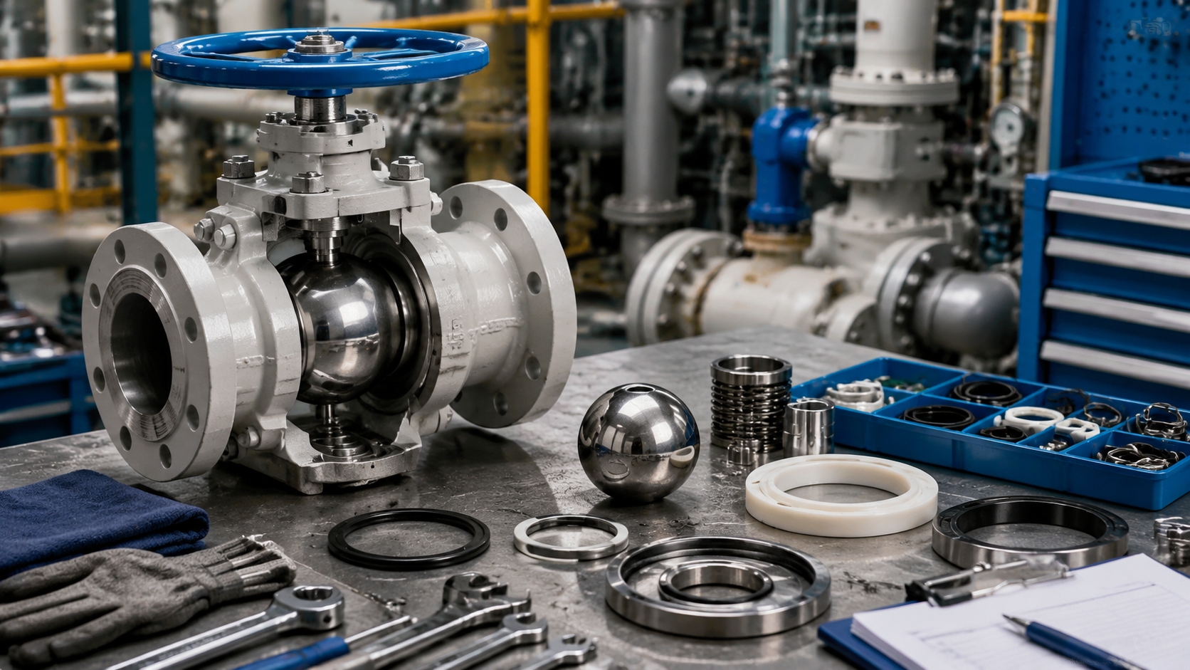
Float Body
The specific gravity of natural gas condensate is typically between 0.62 and 0.78, while free water is close to 1.0. The total weight of the liquid displaced by the float must be greater than the combined weight of its metal shell and internal components. Engineers usually set the float’s specific gravity in the 0.5 to 0.55 range to achieve sufficient upward buoyancy to push the linkage mechanism.
When the system operating pressure reaches the API 6D standard 2500 lb class (equivalent to 41.4 MPa), simply increasing the sphere’s volume will cause the equipment housing to exceed size limits. The outer diameter of common hollow floats in the industry ranges from 50.8 mm (2 inches) to 304.8 mm (12 inches). Taking a 316L stainless steel float with a 150 mm outer diameter as an example, to generate at least 5 Newtons of usable buoyancy in condensate, its metal wall thickness cannot exceed 1.2 mm.
For different pressure ratings (ANSI/ASME B16.5), the common factory specifications for float metal wall thickness are as follows:
- 150 Class (20 bar): 0.5 mm to 0.8 mm
- 300 Class (50 bar): 1.0 mm to 1.2 mm
- 600 Class (100 bar): 1.5 mm to 2.0 mm
- 900 Class and above: Requires internal support structures or increased metal thickness up to 3.5 mm
Thin-walled metals will undergo buckling deformation under external high pressure, and in extreme conditions, will instantly collapse inward. Calculating the critical collapse pressure of a metal sphere requires the material’s elastic modulus; for 316 stainless steel at room temperature, the elastic modulus is approximately 193 GPa. To enhance external pressure resistance, manufacturers will pre-weld 3.0 mm thick reinforcing cross ribs inside the hemispherical shells.
The density of the injected polyurethane foam is strictly controlled between 30 and 50 kg/m³. The closed-cell structure ensures that natural gas molecules cannot completely occupy the physical space inside the sphere. The foaming process is completed in a vacuum chamber below 0.1 standard atmospheres to prevent residual internal air from expanding violently when the temperature rises. When the external natural gas temperature reaches 120°C, the physical increase in internal pressure will act directly on the inside of the metal welds.
The joining of the two hemispherical shells generally utilizes fully automatic Tungsten Inert Gas (TIG) welding, with the welding torch arc temperature reaching up to 3000°C. The entire welding process takes place in a sealed chamber filled with 99.99% pure argon gas to prevent the metal from being oxidized by environmental oxygen or moisture at high temperatures. The weld penetration must reach 100% of the base metal thickness to pass the Non-Destructive Testing (NDT) specifications of the ASME Boiler and Pressure Vessel Code Section VIII.
When the sphere’s wall thickness exceeds 2.5 mm, or when special materials like Monel 400 are used, Electron Beam Welding (EBW) is more widely applied due to its extremely high penetration capability. Electron beam welding is performed in a high vacuum chamber at 10^-4 Torr, forming a weld seam width of only 0.5 to 1.0 mm. The extremely narrow Heat-Affected Zone (HAZ) fully preserves the original mechanical strength of the base metal, reduces the dimensional thermal distortion of the sphere after welding, and controls the physical roundness error to within 0.1 mm.
The factory acceptance test data indicators for the formed metal float include:
- Helium mass spectrometer leak testing: Gas leak rate below 1×10^-9 atm cc/sec
- Hydrostatic testing: Pressurized to 1.5 times the system design pressure and held for 15 minutes
- X-ray Non-Destructive Testing (RT): Covers 100% of the equatorial girth weld; internal porosity must not exceed 1%
- Surface roughness inspection: After electropolishing, the Ra value must be less than 0.4 µm
When processing shale gas containing trace sandstone particles, the high-speed erosion of the fluid will continuously wear the sphere’s surface. Engineers use High-Velocity Oxygen Fuel (HVOF) spraying technology to impact and adhere tungsten carbide powder to the stainless steel outer layer at a speed of 800 m/s. The coating thickness is precisely controlled between 0.15 and 0.25 mm, and the Vickers Hardness (HV) of the metal outer layer can reach over 1200.
The float needs to be connected to an eccentric shaft or a direct-acting valve seat via a physical connecting rod. A metal spud with an internal thread is pre-welded to the top of the sphere, commonly using NPT 1/4-inch or 1/2-inch standard tapered pipe threads. The length of the threaded spud is usually 15 to 25 mm, machined in one pass using a 5-axis Computer Numerical Control (CNC) machine to ensure the concentricity error of the pitch diameter is less than 0.05 mm. After the metal connecting rod is screwed into the spud, an anaerobic thread-locking adhesive capable of withstanding 250°C high temperatures is applied.
In sour gas fields with extremely high concentrations of hydrogen sulfide (H2S), such as those in Alberta, Canada, conventional austenitic stainless steels are mandatorily discarded. Materials pivot to Hastelloy C-276 or industrial pure Titanium Grade 2. The physical density of titanium alloy is only 4.51 g/cm³, 40% lighter than stainless steel, allowing for thicker sheet metal while providing the same upward buoyancy. Hastelloy has an extremely low corrosion rate in acidic liquid mixtures up to 200°C, with an annual metal thickness loss of less than 0.02 mm.
Fluid temperatures downstream of natural gas compressors can experience severe cyclical fluctuations from -20°C to 150°C. The metal sphere and spud strictly follow the physical laws of thermal expansion and contraction; the coefficient of linear expansion for 316 stainless steel is approximately 16.0 µm/(m·°C). When designing a large float with an outer diameter of 300 mm, a temperature increase of 100°C will cause the sphere’s physical diameter to increase by about 0.48 mm. The clearance between the metal baffles and the guide shell inside the system must be set greater than 1.5 mm to prevent the sphere from jamming in the fluid pipeline due to thermal expansion.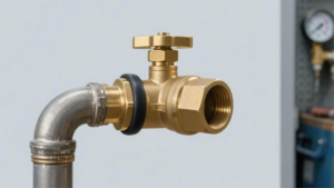
Pressure Rating
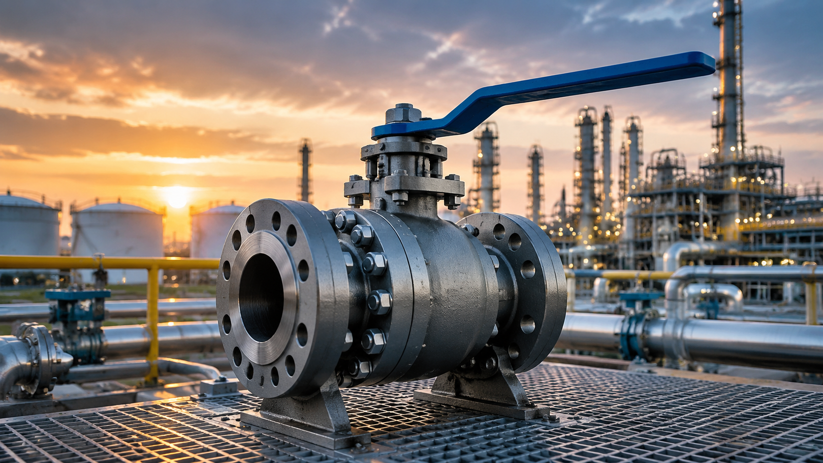
Conventional gas distribution stations mostly choose Class 150 (normal temperature pressure resistance approx. 19.6 bar) to Class 300 (approx. 51 bar), while trunk pipeline networks require Class 600 (approx. 100 bar) and above.
When selecting, ensure that the valve’s pressure rating exceeds the system’s Maximum Allowable Working Pressure (MAWP) by at least 15% to 20%.
Before leaving the factory, the valve body must pass a shell hydrostatic test at 1.5 times the MAWP as stipulated by API 598.
Simultaneously, the collapse pressure of the float body must reach more than 1.2 times the normal pipeline network pressure to prevent mechanical deformation of the hollow sphere under conditions exceeding 600 psi.
Extreme Pressure Limits
Peak pressures can surge to 2.5 times the system design pressure within 0.2 seconds. The cavity and internal components of the float valve bear this transient load in an extremely short time.
The engineering code ASME B31.8 allows natural gas pipelines to briefly exceed the Maximum Allowable Working Pressure (MAWP) by 10% under transient overpressure conditions. The cumulative duration must not exceed 100 hours within one year. When customizing, transient margins must be reserved based on pipe diameter size; the pulse kinetic energy of a 36-inch main network far exceeds that of an 8-inch branch line.
Reciprocating compressors generate continuous gas flow pulsations during operation. The API 618 standard stipulates that the peak-to-peak amplitude of the pulsation accounts for 5% to 15% of the pipeline’s static pressure. Long-term reciprocating alternating stress will lead to fatigue micro-cracks in the valve body.
| Extreme Condition Classification | Pressure Peak Multiplier (vs MAWP) | Duration of Applied Pressure | Physical Damage Manifestation |
|---|---|---|---|
| Emergency Shutdown (ESD) Water Hammer Effect | 1.5 – 2.5x | 0.5 – 2 seconds | Seat extrusion, seal ring tearing |
| Compressor Surge Airflow Pulsation | 1.1 – 1.25x | Occurs continuously | Fatigue fracture, flange bolt loosening |
| Direct Sunlight Thermal Expansion of Closed Cavity | 1.3 – 3.0x | Up to several hours depending on sunlight | Abnormal pressure rise in middle cavity, valve body rupture |
For every 1°F (approx. 0.55°C) increase in ambient temperature, the fluid pressure trapped in the float valve’s middle cavity sharply increases by 70 psi to 100 psi.
Custom float valves need to be configured with an automatic cavity relief mechanism in accordance with API 6D specifications. When the middle cavity pressure exceeds the upstream pipeline pressure by 133 psi to 160 psi, internal components automatically vent the expanded high-pressure gas back into the upstream pipeline to prevent shell burst.
For metal hollow floats acting as liquid level sensing components, the compressive strength is calculated using buckling theory under external pressure. For an 8-inch outer diameter 316L stainless steel float, if a thickness of 0.065 inches (16 Gauge) is used, the compressive collapse point is approximately 450 psi.
In high-pressure natural gas trunk lines, transient extreme pressure will crush standard floats. It is necessary to specify to the supplier the use of 0.120 inches (11 Gauge) or thicker plate stamping and welding, and to require a destructive external static pressure test (Collapse Test) at 2000 psi in a hydrostatic chamber.
The bolts at the flange connection endure high tensile stress under extreme pressure limits. When the internal gas pressure surges to 1500 psi, a joint separation tendency occurs at the flange face, pulling the connecting bolts outward.
- Fasteners must specify ASTM A193 Grade B7 high-strength alloy steel bolts.
- An initial preload stress of 40,000 psi to 60,000 psi must be applied during assembly.
- Ensure that when the system pressure reaches 2.0 times MAWP, the residual compressive force on the flange gasket is greater than the fluid operating pressure.
The extreme Differential Pressure is simultaneously applied to the valve seat and seal ring assembly. When the float valve is closed, maintaining a high pressure of 1200 psi upstream, and the downstream pressure drops to 0 psi due to blowdown, the entire differential pressure thrust is loaded onto the polymer valve seat.
Conventional PTFE (Polytetrafluoroethylene) undergoes cold flow under differential pressures exceeding 800 psi and is extruded from the sealing surface. High-pressure custom components must be replaced with PEEK (Polyether Ether Ketone) or Devlon V-API materials to maintain shape under 3000 psi differential pressure and avoid blow-out by high-velocity natural gas.
| Valve Seat Polymer Sealing Material | Extreme Differential Pressure Threshold | Applicable Operating Temperature Limit | Anti-Cold Flow Yield Strength Characteristics |
|---|---|---|---|
| Pure PTFE (Polytetrafluoroethylene) | 800 psi | 400°F (204°C) | Extremely low, easily deformed under high pressure |
| Glass Fiber Reinforced R-PTFE | 1500 psi | 450°F (232°C) | Medium, improved extrusion phenomenon |
| PEEK (Polyether Ether Ketone) | 3500 psi | 500°F (260°C) | Extremely high, exclusively for ultra-high differential pressure environments |
| Devlon V-API | 3000 psi | 300°F (148°C) | High, dedicated for high-pressure natural gas industry |
The yield strength of common carbon steel ASTM A216 WCB is 36,000 psi, and the upper limit of tensile strength is 70,000 psi.
When calculating the extreme pressure-bearing capacity, based on the ASME Boiler and Pressure Vessel Code (BPVC) Section VIII Division 1, the principal stress at the weak cross-section of the valve body must not exceed 80% of the material’s yield strength under extreme pressure conditions.
In cold regions or high-pressure pressure reduction stations with Joule-Thomson cooling effects, materials will become brittle. It is necessary to use ASTM A352 LCC low-temperature carbon steel, which requires a Charpy V-Notch Test in a -50°F (-46°C) environment, with absorbed energy greater than 20 Joules.
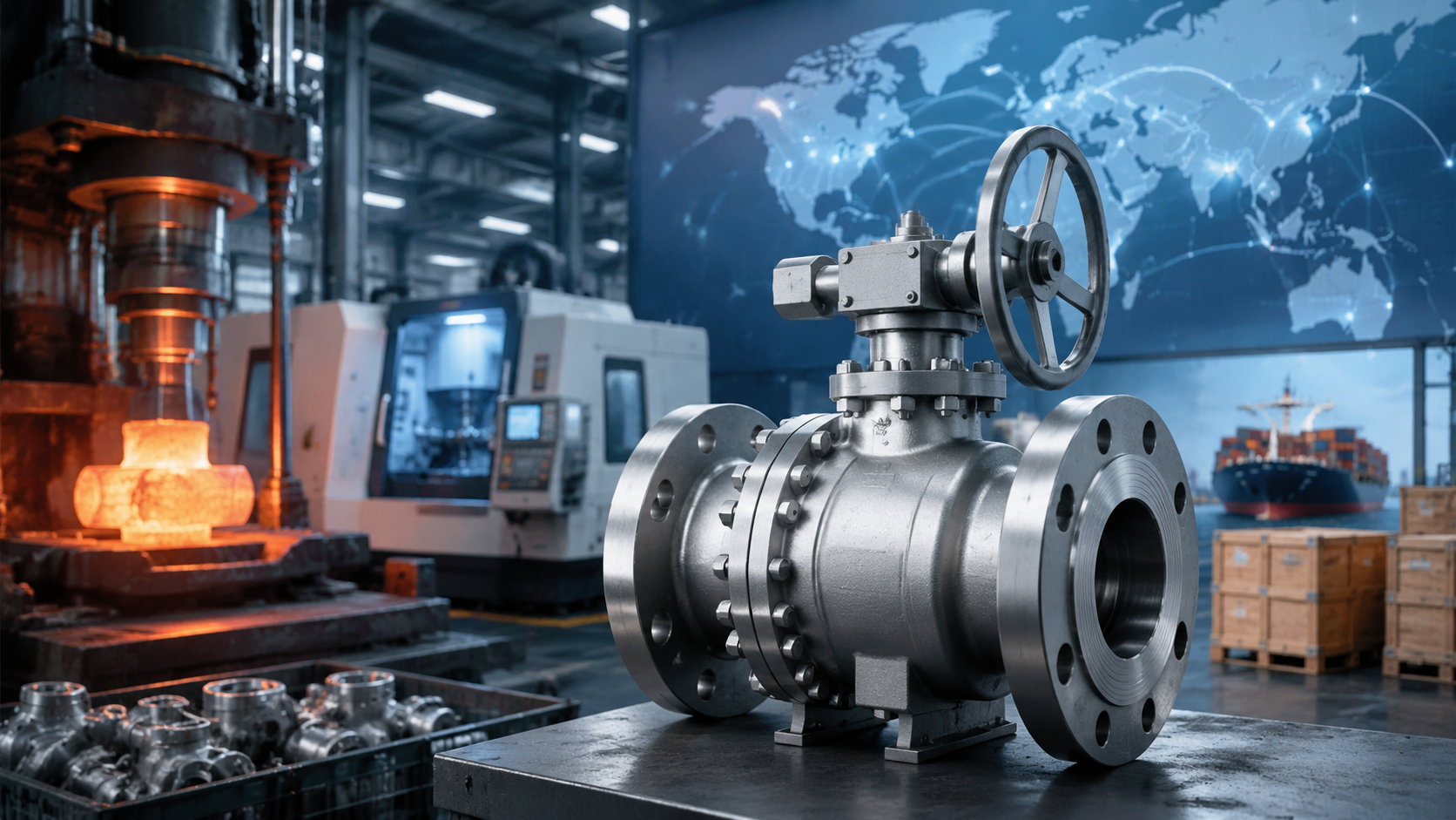
Industrial Standards & Wall Thickness
In natural gas pipeline network engineering, the ASME B16.34 specification sets mandatory physical dimension baselines for valves with flanged, threaded, and welded end connections. The wall thickness of castings or forgings for custom float valves must be strictly calculated according to the “Minimum Wall Thickness Table” in Appendix B of the specification. Taking the common 2-inch (DN50) pipe diameter as an example, the minimum wall thickness for a Class 150 carbon steel valve body is clearly defined as 5.6 mm.
When pipeline pressure requirements increase to the Class 300 standard, the minimum wall thickness metric for the same caliber synchronously increases to 6.4 mm. For the Class 600 rating universally used in compressor outlets or long-distance trunk lines, the wall thickness threshold for a 2-inch valve body jumps to 7.9 mm. During the metal casting or forging phase, factories set machining tolerances as positive tolerances to ensure that the thinnest area after finishing still exceeds the standard baseline by 0.5 to 1.0 mm.
The ASME code system relies on the membrane stress theory for cylindrical pressure vessels as the basis for deriving parameters. The thickness calculation for valve body cavities with an inner diameter greater than 50 mm involves the medium design pressure, the allowable stress of the material at the specified temperature, and the casting quality factor. The allowable stress of ASTM A216 WCB grade carbon steel in the normal temperature range (-29°C to 38°C) is 137.9 MPa.
Natural gas media often carry trace amounts of free water and sour gases; engineering calculations mandate the superposition of a Corrosion Allowance. The American Petroleum Institute API 6D specification recommends an additional 1.5 mm to 3.0 mm of loss allowance layer on top of the base calculated wall thickness. For sour gas field conditions containing hydrogen sulfide (H2S), the NACE MR0175 standard proposes increasing the wall thickness and restricting metal hardness below 22 HRC.
Increasing wall thickness significantly improves the valve’s Pressure-Temperature (P-T) rating performance. Referring to the chart data for Material Group 1.1 in ASME B16.34, a WCB material valve with standard wall thickness withstands a static pressure of 19.6 bar at 38°C. When ambient or medium temperatures soar to 200°C, the material’s physical strength naturally degrades, and the system’s maximum allowable safe working pressure subsequently drops to 13.8 bar.
- Group 1.1 (WCB Carbon Steel): Applicable from -29°C to 425°C, pressure resistance drops approx. 25% at 300°C
- Group 1.2 (LCC Low-Temperature Steel): Applicable from -46°C to 345°C, requires meeting 27 Joules of Charpy impact energy
- Group 2.2 (CF8M Stainless Steel): Applicable down to extreme low -196°C, mostly used in LNG receiving terminals
- Group 2.8 (Duplex Steel): Yield strength reaches twice that of 316L, preferred choice for lightweight pipeline design
Once the valve body wall thickness meets standards, the specifications and dimensions of the connecting flanges at both ends must match the ASME B16.5 specification. The outer diameter of a Class 600 2-inch flange reaches 165 mm, and the thickness of the flange disk itself is no less than 25.4 mm. The flange is evenly distributed with 8 bolt holes of 15.8 mm diameter along its circumference, and field engineers use ASTM A193 B7 high-strength alloy steel bolts tightened with 200 N·m of torque.
Metal spiral wound gaskets standardized by ASME B16.20 are used for physical isolation between flange faces. The inner and outer rings of the gasket are usually 3.2 mm thick; the high-strength flange compresses the gasket’s graphite layer down to 2.5 mm via bolt preload to fill the micron-level machining textures on the flange faces. Flanges with insufficient wall thickness will warp and deform during tightening, losing their sealing capability.
The floating metal sphere inside the valve cavity is similarly constrained by industrial specifications regarding external pressure resistance metrics for thin-shell structures. When subjected to 1000 psi of hydrostatic pressure, a 6-inch diameter sphere made of stamped and welded 316 stainless steel must not have a plate thickness less than 14 Gauge (approx. 1.9 mm). Below this thickness limit, the sphere is highly prone to irreversible denting deformation under gas impact.
For the extreme gas transmission environments of Class 900 (maximum pressure rating approx. 2220 psi), simply increasing the float wall thickness will lead to excessive dead weight, preventing it from generating the rated buoyancy in liquid hydrocarbons. European and American manufacturers often use a laser deep penetration welding process, injecting 600 psi of high-pressure inert argon gas into the cavity to balance the internal and external pressure difference before the closed assembly of the 2.5 mm thick hemispheres.
- Helium external pressure leak test: Inspected by submersion in a pressurized chamber, maintaining 15 minutes with no bubble emission on the surface
- Destructive collapse test: 2% of finished products are extracted and pressurized until complete failure, thoroughly recording the burst peak
- Non-destructive Radiographic Testing (RT): Inspects the internal weld penetration and microscopic porosity of the sphere’s equatorial weld
- Weight and buoyancy calibration: Precision strictly controlled within ±5 grams to ensure accuracy of the displacement calculation model
Procurement specifications for large natural gas projects require suppliers to provide X-ray films complying with the ASTM E446 standard to ensure the internal shrinkage porosity rating of the valve body’s pressure-bearing area reaches Level 2 or better. Against severe high-frequency vibrations that may occur in high-pressure compressor piping, the uniformity of wall thickness is of greater engineering significance than a localized thickness increase.
A valve body with sufficient thickness can maintain the geometric dimensional stability of the valve seat mounting groove while withstanding the axial tensile stress generated by thermal expansion and contraction of the pipeline. When temperatures in cold region pipelines drop by 50°C, a 10-meter-long carbon steel pipe will experience a linear shrinkage of about 6 mm. The high-strength thick-walled valve body absorbs the transferred axial pulling force of several tons, preventing the internal valve seat from undergoing millimeter-level elliptical physical deformation.
When inspecting equipment on-site, international natural gas project owners first verify the identification codes cast on the outer wall of the valve body. In accordance with the MSS SP-25 specification, the side of a custom valve body is mandatorily required to be cast or deeply stamped to indicate: the manufacturer’s logo, pressure class (e.g., 300), material code (e.g., WCB), and melt Heat Number.
Through the 5-digit heat number code, field engineers can precisely trace back to the original physical inspection reports, such as carbon equivalent values and tensile strength from the day of smelting at the steel mill. Once the localized thickness measured by a micrometer falls below the ASME specification baseline, even if the hydrostatic test passes, the entire batch of valves will still be deemed non-compliant and required to be returned to the factory for recasting.
Float Cavity Compressive Strength
Under a pipeline operating pressure of 1500 psi, the surface of an 8-inch outer diameter sphere bears a total inward squeezing force of over 300,000 pounds. External loads exceeding the material’s yield limit will trigger elastic instability, causing the metal structure to instantly collapse inward.
The yield strength of conventional 316L stainless steel in a 100°F (38°C) environment is 25,000 psi. When the external environmental pressure crosses the critical point of instability, minor geometric deformation will rapidly amplify into irreversible metal collapse.
The external pressure calculation model of the ASME Boiler and Pressure Vessel Code Section VIII indicates that the compressive collapse point of a sphere is directly proportional to the square of the wall thickness and inversely proportional to the square of the radius.
The metal wall thickness parameter strictly defines the collapse threshold. If a 6-inch outer diameter float uses a 0.065-inch (16 Gauge) wall thickness, it ruptures at approximately 600 psi in a hydrostatic chamber. By thickening the plate to 0.109 inches (12 Gauge), its collapse pressure limit is significantly raised to 1450 psi.
Increasing wall thickness introduces a physical trade-off between weight and buoyancy. A 6-inch sphere with a 0.120-inch wall thickness has a dead weight of 3.2 pounds, while the total buoyancy generated by displacing an equal volume of water is only 4.1 pounds. The specific gravity of natural gas condensate is typically between 0.65 and 0.75; the low-density fluid reduces the usable net buoyancy.
To overcome the frictional resistance of the stuffing box and trigger the valve linkage, the component must maintain an upward net thrust of at least 0.5 pounds in low-density media.
- Standard Wall Thickness (0.048 inches): Applicable for low-pressure two-phase separators with static pressure below 300 psi.
- Thickened Customization (0.109 inches): Deployed in 1200 psi medium-pressure natural gas gathering station trunk lines.
- Extra Thick Forging (0.188 inches): Deals with harsh operating conditions of 2500 psi deepwater platforms.
The equatorial Tungsten Inert Gas (TIG) weld seam in the manufacturing process forms a Heat-Affected Zone (HAZ). High-temperature deposition reduces the yield strength of the area surrounding the weld by 15% to 20%. The uneven distribution of material strength becomes the initial breakthrough point for asymmetrical denting under extreme high pressure.
A comprehensive solution annealing treatment at 1900°F (1038°C) must be conducted after welding, followed by a rapid water quench to restore a uniform austenitic metallographic structure. The heat treatment process compensates for the strength degradation at the weld seam, safeguarding the overall compressive consistency of the spherical shell.
The NACE MR0175/ISO 15156 specification strictly mandates that the Rockwell hardness in the 316L weld zone under hydrogen sulfide conditions must not exceed 22 HRC, preventing sulfide stress cracking under high pressure.
To break through the buoyancy bottleneck caused simply by increasing wall thickness, internal cavity pre-pressurization technology is adopted in engineering. During the manufacturing stage, high-purity nitrogen gas at 500 psi is injected into the hollow metal sphere to establish outward support force. The injected inert gas offsets a significant portion of the external fluid load.
In a 1500 psi external pipeline network, the net differential pressure borne by the pre-pressurized float’s metal shell drops to 1000 psi. This process change allows the factory to use thinner 0.083-inch (14 Gauge) plates, reducing weight by 1.2 pounds while maintaining the collapse rating, thereby boosting operating buoyancy by 35%.
Facing pressure ratings of Class 1500 and above, network peaks may touch 3600 psi. Extreme pressures exceed the bearing limit of austenitic stainless steel hollow structures. Alternative solutions shift to high-strength alloys or solid foam materials.
- Monel 400 Alloy: Yield strength reaches 40,000 psi; compressive upper limit is 40% higher than 316L.
- Titanium Alloy (Grade 5): Yield strength as high as 120,000 psi; weight reduced by 45%, perfectly fitting extreme pressure requirements.
- Closed-Cell Foam Filling: Internally injected with synthetic polyurethane of 15 lbs/ft³ density, completely eliminating the gas cavity.
Syntactic foam consists of hollow glass microspheres embedded in an epoxy resin matrix. This synthetic material maintains zero deformation under an extreme hydrostatic pressure of 5000 psi, while having a specific gravity of only 0.45, providing a buoyancy-to-pressure ratio superior to any metal hollow sphere.
Before leaving the factory, products must enter a high-pressure test chamber to perform a destructive external pressure inspection. According to the ISA-75.19.01 specification, the test pump steadily increases the environmental water pressure at a rate of 100 psi per minute until telemetry equipment captures a permanent sudden reduction in volume.
Industrial acceptance specifications calibrate that the rated collapse failure pressure of the float must exceed 1.5 times the system’s Maximum Allowable Working Pressure (MAWP).
The pressure application test allows for extremely minor elastic deformation, but the volume reduction must not cross the 2% boundary. If a float with a volume of 100 cubic inches is crushed and loses 2 cubic inches of volume, the buoyancy curve shifts, and it will be unable to output sufficient mechanical thrust to open the valve seat.
Geometric true roundness is another manufacturing data point affecting the compressive threshold. An ovality deviating by 0.05 inches from a perfect sphere will cause the theoretical collapse limit to drop by 25%. Employing precision hydroforming instead of traditional mechanical deep drawing controls the roundness error to within 0.01 inches.
Emergency blowdowns in natural gas pipeline networks induce reverse alternating loads. For floats pre-charged with nitrogen or those where high-pressure gas has entered the cavity due to micro-pore leakage, the external pressure suddenly drops to 0 psi at a rate of 100 psi per second, instantly converting 1000 psi of internal pressure into outward bursting tension.
To prevent weld tearing under rapid decompression environments, the shell seams must pass 100% Radiographic Testing (RT). Testing standards require identifying pores or incomplete penetration defects as small as 0.005 inches, ensuring the physical integrity of the metal cavity under dual-directional extreme pressure differentials.
Seal Integrity
Natural gas molecules are extremely small and highly penetrating; the leakage tolerance in standard tests must be below 0.15 ml/min.
Material matching must be determined according to specific working conditions: conventional pipelines use Nitrile Butadiene Rubber (NBR, applicable from -40°C to 121°C and within 1500 psi);
If the hydrogen sulfide (H2S) concentration exceeds 0.3%, Viton AED materials complying with NACE MR0175 standards (Anti-Explosive Decompression, temperature resistant to 200°C) must be utilized;
High-pressure (over 2500 psi) or extreme cold (-50°C) systems require matched modified PTFE.
Simultaneously, the surface roughness of the metal float must be machined to Ra 0.1 μm to guarantee physical fit.
Valve Sealing Test
The testing process is executed in accordance with the American Petroleum Institute’s API 6D specification. The test bench fixture applies 3000 to 5000 psi of axial load to secure the valve body. Operators bolt the test flanges to both ends of the valve and connect the high-pressure gas source and measurement instrumentation.
In the first phase, the factory pumps in deionized water that has undergone reverse osmosis treatment. Technical specifications require the chloride ion content in the water to be strictly controlled below 30 ppm to prevent pitting corrosion on internal stainless steel components. The water pressure is pressurized to 1.5 times the valve’s rated room-temperature working pressure.
Taking a Class 600 float valve as an example, the shell test pressure at this point will reach 2225 psi. The holding time is determined by the valve size; valves from 2 to 6 inches maintain a holding period of at least 3 minutes. Operators observe the magnitude of the numerical drop using a digital pressure gauge calibrated to an accuracy of 0.5% full scale.
For natural gas conditions, the reference standard for gas seal testing shifts to ANSI/FCI 70-2. The test gas source uses industrial nitrogen with a purity of 99.9%. Low-pressure air-tightness testing is typically conducted around 80 psi. High-pressure air-tightness testing raises the nitrogen pressure to 1.1 times the valve’s maximum allowable working pressure at 38°C.
A polyurethane hose with an inner diameter of 0.25 inches directs escaping gas from the valve seat seal to a position 0.5 inches below the water surface. Inspectors quantify test results by observing the frequency of bubbles generated in a measuring cylinder. ANSI/FCI 70-2 classifies 6 levels, and natural gas systems typically mandate achieving the highest level, Class VI tight shut-off.
| Nominal Valve Size (Inches) | Allowable Nitrogen Test Leakage (ml/min) | Allowable Bubble Count (bubbles/min) | Minimum Hold Time (minutes) |
|---|---|---|---|
| 1 to 2 | 0.15 | 1 | 1 |
| 3 to 4 | 0.30 | 2 | 2 |
| 6 | 0.45 | 3 | 2 |
| 8 | 0.60 | 4 | 4 |
When the pipeline transports mixed natural gas containing over 10% high-concentration hydrogen, an ordinary nitrogen bubble test cannot meet leak detection precision requirements. The factory must instead employ a helium mass spectrometer leak detector for micro-leak rate detection. The test is conducted under a high vacuum environment, where the external background vacuum level must be pumped down to below 10^-3 mbar using a mechanical pump.
Helium has an extremely small atomic radius of 0.26 nanometers, allowing it to penetrate minuscule metal machining defects. The detector’s sniffer probe scans the periphery of the valve seat at a speed of 10 mm/s to capture escaping helium atoms. According to the ISO 15848-1 standard for fugitive emissions of volatile organic compounds, when using helium testing, the upper limit of leakage rate for Class A sealing is restricted to 10^-5 mg·s^-1·m^-1.
Specific on-site high-level verification procedures are typically subdivided into the following four mechanical steps:
- Inject water at 1.5 times the working pressure into the half-open valve body cavity and hold for 15 minutes to verify the compressive capability of the 15 mm thick shell wall.
- The valve is transitioned to a fully closed state; nitrogen at 1.1 times the working pressure is applied to the high-pressure side, and a high-precision mass flow meter is connected to the low-pressure side.
- Maintaining a constant differential pressure, an acoustic emission ultrasonic detector is attached to the exterior of the valve body, with the frequency channel set between 35 kHz and 45 kHz to listen for internal micro-airflow friction sounds.
- Cycle the valve between fully open and fully closed 200 times to simulate 6 months of physical wear during use, followed by a re-test with an 80 psi low-pressure bubble test.
Normal room-temperature testing is conducted in shop environments between 5°C and 40°C. For natural gas equipment installed in extreme cold regions like Alaska, the test bench is placed into a dedicated liquid nitrogen refrigeration chamber. The temperature inside the chamber is lowered at a cooling rate of 20°C per hour down to -46°C or an even lower -196°C.
After being held at extreme low temperatures for 2 hours, the internal Teflon seal rings undergo physical contraction. Operators then re-introduce 150 psi of high-pressure helium and let it stand for 15 minutes. Detection instruments re-measure the leakage volume per minute, confirming whether it still remains within the 0.15 ml allowable limit specified in the table above.
Fire testing conducted in accordance with the API 607 specification is another independent verification procedure. The valve is fixed above an industrial burner; the pipeline is filled with liquid water and maintained at a 30 psi back pressure. Six flame nozzles ignite simultaneously, causing the ambient temperature around the valve body to soar to between 750°C and 1000°C within 15 minutes. Four externally positioned thermocouples continuously record the temperature profile of the metal surface.
Soft seals will completely burn and melt at temperatures of 750°C. At this point, the spring preload mechanism will push the internal 316 stainless steel valve seat against the metal float, forming a secondary pure metal-to-metal physical seal. Over the sustained 30-minute burning period, the amount of water leakage flowing through the valve seat into the downstream collection vessel is strictly limited, not to exceed 400 ml/min/inch.
After the combustion test ends, the valve must be forcefully water-cooled to below 100°C within 10 minutes. Operators subsequently raise the internal water pressure back to 50 psi and test the sealing condition of the external stuffing box with the valve in the fully open state. Under this state, leakage to the external environment is required not to exceed 100 ml/min/inch.
Materials & Natural Gas
Conventional above-ground natural gas gathering and transmission pipelines typically use cast carbon steel ASTM A216 WCB, whose lower limit for applicable ambient temperature is specified as -29°C.
When the ambient temperature plummets, ordinary WCB material is prone to brittle fracture. In extreme cold gas fields in North America, Canada, or Alaska, pipeline valves must be upgraded to low-temperature carbon steel ASTM A352 LCC.
In a Charpy V-notch impact test at -46°C, LCC material is capable of absorbing impact energy of over 20 Joules. The abundant toughness indicator ensures that the metal shell will not shatter under high-pressure physical impact of 1500 psi.
Unfiltered wellhead natural gas typically contains moisture, hydrogen sulfide (H2S), and carbon dioxide (CO2). When the water content exceeds 7 pounds/million standard cubic feet (MMscf) and is accompanied by CO2, a highly corrosive carbonic acid environment forms internally.
Under the aforementioned sour wet gas conditions, the annual corrosion rate of carbon steel pipe walls generally exceeds 0.1 mm. System engineers will specify the use of ASTM A351 CF8M (316 cast stainless steel) as the primary valve body material.
The 316 stainless steel material has 2% to 3% molybdenum added. Ample molybdenum content can effectively resist localized pitting induced on metal surfaces by wet natural gas.
Facing sour natural gas with a hydrogen sulfide concentration exceeding 0.3%, the probability of Stress Corrosion Cracking in austenitic stainless steel rises significantly, and material configuration must follow the standards set by the National Association of Corrosion Engineers (NACE).
- Rockwell hardness of metal components is mandatorily limited to below HRC 22.
- Carbon steel base material must undergo Post-Weld Heat Treatment (PWHT) to relieve internal residual stress.
- Austenitic stainless steels must be used in a solution annealed heat-treated condition.
- Pressure boundary flange fasteners must comply with ASTM A193 B7M low-hardness specifications.
Coastal natural gas terminals or offshore drilling platforms face the dual corrosion of internal sour gas and external high-salt marine atmospheres. 316 stainless steel is prone to Chloride Stress Corrosion Cracking in environments where chloride ion concentration exceeds 1000 ppm.
System design specifications will require the use of duplex stainless steel ASTM A890 Grade 4A or 5A materials. Duplex stainless steel is composed of a 50% ferrite and 50% austenite structure; its base yield strength reaches 450 MPa, which is twice that of ordinary austenitic stainless steel.
The quantitative indicator for assessing the corrosion resistance of duplex stainless steel is the Pitting Resistance Equivalent Number (PREN). On offshore natural gas platforms, the material’s PREN value is required to be greater than 40 to resist free chloride attacks up to 20,000 ppm in seawater.
Floats and valve stems are submerged long-term in natural gas media flowing at over 20 meters/second, enduring continuous mechanical friction. The standard internal trim base material selection for natural gas valves is 316 stainless steel or 17-4PH precipitation-hardening stainless steel.
17-4PH stainless steel in an H1150+1150 double aging heat treatment state can provide a yield strength of 725 MPa. The high-strength metal skeleton prevents the valve stem from twisting and deforming under a differential pressure resistance of 2500 psi.
Factories perform an Electroless Nickel Plating (ENP) process on the float surface, with the metal coating thickness precisely controlled at typically 0.003 inches (approx. 75 microns).
- Electroless Nickel Plating (ENP): Matches conventional filtered dry natural gas pipelines
- Tungsten Carbide Spray (HVOF): Hardness reaches 70 HRC, resisting wellhead raw gas carrying quartz sand
- Hard Chrome Plating: Coating thickness 0.002 inches, provides an extremely low surface friction coefficient
- Stellite Alloy Hardfacing: Anti-high-temperature oxidation, suitable for natural gas compression ends above 200°C
When the H2S concentration in natural gas pipelines reaches 10% or even higher, accompanied by a large amount of free water, the physical structure of duplex stainless steel will also be destroyed. Nickel-based alloys are the standard isolation barrier in high-concentration hydrogen sulfide environments.
The chemical composition of Inconel 625 nickel-chromium-molybdenum alloy contains approximately 58% nickel and 20% chromium. The high content of nickel elements provides extremely strong chemical inertness against high-concentration sulfide gases.
Monel 400 copper-nickel alloy is specifically used to handle natural gas mixtures accompanied by high concentrations of hydrofluoric acid or large volumes of fluid seawater. Its composition contains 63% nickel and 28% to 34% copper, and its annual corrosion rate in reducing media is below 0.02 mm.
In large natural gas pipeline valves with diameters of 24 inches and above, instead of solid casting, it is common practice to overlay a 3 mm thick Inconel 625 alloy layer onto the inner wall of a carbon steel valve body.
Flange connection studs for conventional onshore pipelines use ASTM A193 B7 alloy steel, paired with ASTM A194 2H heavy hex nuts.
In severely cold gas regions with temperatures below -29°C, stud materials must be concurrently changed to ASTM A320 L7. Exposed bolts in marine atmospheric exposure environments require hot-dip galvanizing or coating with a Xylan PTFE coating, with the coating thickness set at 25 microns.
The metal gaskets connecting the valve body flanges commonly utilize a 316 stainless steel spiral wound flexible graphite filler. The graphite filler can withstand high temperatures of 450°C and maintains a physical seal for over 15 minutes during external open-flame combustion, meeting the parameter requirements of the API 607 valve fire test.
Handling Sudden Pressure Drops
In the North American API 6D pipeline valve specification, a typical test scenario for Emergency Shutdown (ESD) valves is venting 1500 psi of high-pressure natural gas down to 0 psi within 10 seconds. Under high-pressure conditions, minuscule methane molecules will permeate and dissolve into the polymer molecular chain gaps of conventional rubber O-rings, achieving internal pressure equilibrium.
The expansion rate of the internal gas far exceeds its diffusion and escape rate from the polymer, causing the rubber surface to develop blisters, micro-cracks, or even undergo complete chunking and spalling.
To withstand physical tearing under differential pressures up to 2500 psi, seal formulas must be upgraded to high-density elastomeric materials specifically designed for Anti-Explosive Decompression (AED). The hardness of Nitrile rubber in conventional natural gas valves is around Shore A70, whereas the hardness of AED-certified Fluoroelastomers (FKM) is forcefully elevated to Shore A90 or even A92. The high hardness rating equips the polymer with extremely high tensile yield strength, sufficient to resist the outward tension of over 10 Megapascals generated when residual internal gas expands outward. The explosive decompression resistance of materials requires verification through rigorous laboratory procedures under Norsok M-710 or the International Organization for Standardization’s ISO 23936-2.
- The mixed gas ratio is set to 90% methane plus 10% carbon dioxide
- The test cycle requires maintaining 150 bar pressure at 100 degrees Celsius for 72 hours
- The decompression rate is strictly controlled between 20 bar to 40 bar per minute
- After 8 consecutive cycles of pressurization and decompression, the O-ring cross-section is dissected and examined
Test ratings are categorized from Level 0 to 5; materials scoring Level 0 and 1, where the total length of internal cracks does not exceed 10% of the cross-sectional diameter and there are no external blisters, are permitted for use in high-pressure natural gas trunklines. Beyond material hardness, the mechanical confinement space (Gland Design) percentage of the O-ring inside the metal groove serves as the physical defense line against decompression failure. The groove fill ratio for standard hydraulic seals is usually between 70% and 75%, leaving substantial space for the rubber to expand under heat or deform under pressure. In float valves designed for natural gas pressure drops exceeding 1000 psi, the gland fill ratio for AED seal rings is compressed by engineers to 85% to 90%.
The extremely narrow redundant space tightly wraps the rubber part within the metal cavity, physically limiting the magnitude of volumetric expansion the polymer undergoes during a sudden pressure drop.
When the system operating pressure exceeds ASME Class 1500 (working pressure approaching 3700 psi), the vast majority of elastomeric rubbers struggle to endure the instantaneous physical shock brought about by emergency blowdown. High-pressure Blowout Preventers (BOPs) at natural gas wellheads or main gas gathering manifold valves will abandon rubber O-rings in favor of spring-energized Polytetrafluoroethylene (PTFE) lip seals. The molecular lattice of PTFE material is extremely dense, with a gas permeability less than one-hundredth that of FKM, fundamentally blocking massive amounts of natural gas molecules from infiltrating the interior of the material. High-molecular polymers lack the resilience of rubber and cannot spontaneously fit against the metal valve seat to form an effective block during the 0 to 50 psi low-pressure startup phase. The spring-energized seal is internally embedded with a V-shaped or U-shaped Elgiloy cobalt-chromium-nickel alloy spring, which continuously releases a constant mechanical outward thrust of 15 to 30 pounds across a -200 to 280 degree Celsius range.
This continuous mechanical thrust forces the PTFE lip to tightly bite onto the metal float surface, compensating for the low-pressure sealing gap that exists without medium pressure assistance. Sudden pressure drops are accompanied by severe thermodynamic Joule-Thomson effects, where the high-speed expansion of gas absorbs massive amounts of environmental heat. During the 3-minute blowdown process from 1500 psi down to atmospheric pressure, localized metal temperatures of the valve cavity and surrounding piping will suddenly plunge by 40 to 60 degrees Celsius. When natural gas contains moisture exceeding 5 pounds/million standard cubic feet, the instantaneous extreme low temperatures will cause water vapor to condense into hard ice crystals or natural gas hydrates at the clearance between the valve seat and the float.
The Mohs hardness of the ice crystals can reach levels 4 to 5, and upon the next valve opening, the edges of the ice blocks will score grooves deeper than 0.2 mm into the polymer valve seat.
To prevent physical scratching caused by extreme cooling, the valve seat structure is supplemented with a PEEK (Polyether Ether Ketone) backup ring acting as front-end protection.
PEEK material can still maintain a tensile strength of 100 MPa in an extreme cold state of -60 degrees Celsius, functioning as a hard scraper to scrape off the condensed ice layer attached to the surface of the float.
The PEEK ring, combined with externally injected methanol or ethylene glycol antifreeze (at a concentration of 20% to 30%), maintains the smooth operation of internal mechanical components after they have experienced severe pressure drops and freezing.

")