
Undersized float valves cause a closing delay of over 10 seconds, resulting in a single overflow of 3 liters;
Inferior seals are prone to leakage under 0.5 MPa water pressure.
Strict 1:1 sizing matching the pipe diameter is required, paired with a Shore hardness 70 EPDM O-ring, and the static water level must be set 5 cm below the overflow port to ensure a rapid, zero-drip shutoff within 2 seconds, eliminating water waste.
Wrong Sizing
Under standard municipal water pressure of 60 psi, if a small 4-inch float adapted for a 1/2-inch pipe is incorrectly installed on a 1-inch inlet pipe, the buoyancy it provides is 35% lower than the force required to close the valve.
This leaves a 2 mm gap at the valve core, causing a continuous overflow of approximately 1.2 gallons per minute (GPM).
Calculated using Los Angeles water rates, a single incorrectly sized float valve wastes over 51,000 liters of clean tap water per month.
Proper selection requires strict fluid dynamic matching of the NPT pipe diameter, inlet line system pressure (psi), and the water displacement volume of the float.
Pipe Diameter
In a conventional 50 psi municipal water supply system, forcing a 3/4-inch inlet pipe into a 1/2-inch float valve via a reducer creates a severe hydrodynamic throttling effect at the valve body inlet. Pipe contraction causes the water flow rate to plummet from the originally designed 22 GPM to 14 GPM. In a 300-gallon outdoor livestock water trough in Arizona, the reduced flow extended the filling cycle from 14 minutes to 22 minutes. The operating time of the water supply system’s booster pump was prolonged, consuming about 1.2 kWh of extra electricity daily. Prolonged low-flow, high-pressure physical impact accelerates metal cavitation within the brass valve body’s internal channels, resulting in wear pits 0.5 mm deep after 7 months of use.
On a compact 50-gallon makeup water tank, installing a 2-inch industrial high-flow float valve achieves a filling speed of 120 GPM. The water level rapidly rises to the maximum set point within 25 seconds, and the float pushes the lever and valve core violently toward the inlet with extreme acceleration. The mechanical valve shuts completely within 0.2 seconds, forcefully cutting off the water flowing at 8 feet per second inside the pipe. The fluid’s kinetic energy instantly converts into pressure within the pipe network, generating a transient high-pressure wave up to 400 psi, causing severe physical water hammer damage.
Physical Parameter Adaptation Table for Different NPT Pipe Diameters and Tank Volumes
| Inlet Pipe Diameter (NPT) | Standard Flow Rate at 50 psi | Recommended Minimum Tank Volume | Estimated Water Hammer Pressure from Instant Valve Closure |
|---|---|---|---|
| 1/2 Inch | 14 GPM | 30 Gallons | 150 psi |
| 3/4 Inch | 22 GPM | 75 Gallons | 210 psi |
| 1 Inch | 35 GPM | 150 Gallons | 280 psi |
| 2 Inches | 120 GPM | 1000 Gallons | 450 psi |
Float valves marketed with 1-inch NPT external threads often have actual internal physical water passage holes machined to 3/8-inch or 1/2-inch. In a high-rise rooftop water storage project in Denver, Colorado, engineers selected full-port valves with a 3/4-inch internal bore based on the pipe’s outer diameter. When the water supply network pressure was maintained at 75 psi, the opening water flow resistance generated by the full-port valve was 60% higher than that of a standard bore valve. The system’s original 8-inch polyethylene plastic float could not provide sufficient upward closing force. A steady, unnoticeable overflow of 0.8 GPM occurred at the bottom of the tank, losing over 34,000 gallons of municipal tap water in a month.
Physical dimensional differences in interface thread standards cause slow water seepage at pipe connections. The U.S. piping market uses the National Pipe Thread (NPT) standard, processed with a physical taper of 1 degree 47 minutes.
- Mismatched Thread Angles: Screwing a brass float valve with British Standard Pipe Taper (BSPT) threads into an NPT-spec PVC fitting results in a mechanical deviation of 5 degrees, as their thread angles are 55 degrees and 60 degrees, respectively.
- Insufficient Engagement Depth: Forcible tightening only guarantees metal engagement for the first 3 threads, leaving a physical gap of 0.1 to 0.3 mm in the subsequent thread sections.
- Thread Seal Tape Failure: Under a network static pressure of 60 psi, 4 wraps of PTFE thread seal tape will be penetrated by high-pressure water molecules after 48 hours.
- Quantified Leakage Loss: A trace leakage of 150 ml per hour forms at the thread gap, accumulating a wasted 340 gallons of water resources over a year.
When the pipe diameter is undersized and the system pressure exceeds 80 psi, the inlet flow velocity surpasses 12 ft/s. The physical scouring of high-speed water drastically increases the surface roughness of the Nitrile Rubber (NBR) sealing gasket on the valve seat. In a commercial greenhouse irrigation reservoir in Florida, after 6 months of continuous operation, a 3 mm thick rubber gasket was cut by the water flow into a groove 0.8 mm wide. Water continuously dripped into the tank along this microscopic groove at a rate of 5 drops per second, triggering 3 false alarms per day from the bottom groundwater level detector.
Brass has a linear expansion coefficient of 1.8×10^-5 per degree Celsius, while 304 stainless steel’s parameter is 1.6×10^-5. In outdoor exposed facilities with day-night temperature differences reaching 40°F, a relative physical displacement of 0.02 mm occurs at the joints of 1.5-inch large-diameter pipes. Repeated thermal expansion and contraction deformation cause microscopic fractures in the industrial sealant within the threads, inducing chronic dripping outward along the pipe wall.
On cantilever-mounted PVC inlet pipes, an oversized metal float valve body exerts downward physical gravity torque on the pipe’s end. A 2-inch cast brass float valve, combined with a 12-inch brass lever and a 10-inch copper float, has a total weight exceeding 14 pounds. Installing it on a 1-inch Schedule 40 PVC pipe extension without any bottom bracket support combines gravity with the vertical impact force of water flow opening and closing, subjecting the PVC pipe’s solvent-welded joint to a continuous bending stress of 120 psi. After 8 months of operation, subtle stress cracks 2 mm long appeared on the underside of the PVC pipe wall, and the pipe mouth broke, unleashing an uncontrolled water surge of 600 gallons per hour.
In an industrial water treatment plant in Houston, Texas, engineers abandoned the plan of installing a single giant float valve weighing 35 pounds at the end of a 3-inch main water supply pipe. Instead, a custom 304 stainless steel distribution manifold was installed, dividing the 3-inch main line into four 1-inch branch lines with equal hydrodynamic cross-sectional areas. Each branch was individually equipped with a standard 1-inch brass float valve, evenly distributing the system water flow pressure and keeping the flow velocity in each pipe at a safe 6 ft/s. The four independent valves each connected to an 8-inch plastic float, distributing the 320 pounds of physical total thrust required to close the valves across four independent mechanical lever fulcrums. The mechanical wear borne by a single component was reduced by 75%, extending the failure-free operating time of the entire water level control module from 12 months to 36 months.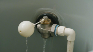
Float Volume
The internal volume of an 8-inch diameter polyethylene float is approximately 268 cubic inches. In 70°F freshwater, the fluid displaced when fully submerged generates about 9.6 pounds of upward physical thrust. When this device is connected to a 12-inch long brass lever, it is mechanically amplified at the fulcrum to over 40 pounds of physical closing force.
In a 150-gallon commercial reverse osmosis reservoir in Phoenix, Arizona, operators replaced the original 8-inch float with a 6-inch standard piece having a volume of only 113 cubic inches. The volume was reduced by 57%, causing the maximum upward buoyancy in the tank to plummet to 4.1 pounds.
The static water pressure of the source pipe network is maintained at 65 psi year-round. The 4.1 pounds of buoyancy, mechanically amplified through a 9-inch lever arm, only generates 18 pounds of upward thrust at the valve end. The water flow pressure exerts 22 pounds of reverse physical impact force on the 1/2-inch internal valve core section.
This force imbalance creates a 0.6 mm gap between the neoprene sealing gasket and the brass valve seat. Tap water continuously leaks into the reservoir through this micro-channel at a rate of 0.4 GPM. Over 72 hours of uninterrupted operation, the overflow pipe discharged more than 1,700 gallons of filtered water.
Changes in the physical volume of the float trigger a chain reaction of fluid dynamic data:
- For every 10% reduction in volume, the total buoyancy at standard water temperature drops by an average of 1.2 pounds.
- The thrust generated by a 6-inch plastic sphere cannot resist a municipal water supply network static pressure exceeding 50 psi.
- When the ambient water temperature rises to 120°F, the drop in fluid density cuts 2% off the theoretical calculated buoyancy.
- Increasing the polycarbonate shell thickness by 2 mm consumes 15 cubic inches of internal air displacement volume.
A 5-inch diameter sphere was pre-loaded with 150 grams of quartz sand. The extra counterweight is used to prevent the component from mechanical oscillation and false triggering in 30 mph wind gusts.
The internal sand occupies 8% of the sphere’s physical space and increases the overall gravity. The sinking weight offsets part of the buoyancy of the displaced liquid when submerged. To overcome the 60 psi well pump pressure, the water level in the trough must submerge over 85% of the sphere’s vertical height to trigger the mechanical valve to fully close.
A fully loaded 5-inch float in the closed moment leaves only 1.5 inches of physical safety clearance from the trough’s top edge. A 1,400-pound cow drinking water creates surface undulations up to 3 inches high. Water flows over the edge, causing an additional splash loss of 25 gallons per day onto the soil.
The density and structural design of the manufacturing materials significantly impact the utilization ratio of the displacement volume:
- A 0.8 mm thick copper shell provides higher compressive strength to maintain the sphere’s physical shape.
- High-Density Polyethylene (HDPE) material is lightweight, achieving a 92% utilization rate of the water displacement volume.
- An elliptical design increases the displacement volume by 20% compared to a perfect sphere within the same vertical space.
- Internal foam filler additionally consumes 12% of the sphere’s theoretical air buoyancy.
- A 0.5 mm thick calcium carbonate scale attached to the surface adds 28 grams of overall weight.
In a hotel cooling tower in Las Vegas, Nevada, engineers customized a cylindrical physical buoyancy device. The cylinder’s diameter was set to 4 inches, extending horizontally to 14 inches in length. This shape provided 175 cubic inches of displacement volume, equivalent to a 7.5-inch perfect sphere, in a narrow 10-inch wide water level control trough.
For every 1 inch the water level rises, the 14-inch long cylinder displaces 3 times more water than a 4-inch perfect sphere. In a 75 psi cooling water circulation network, the water level only needs to rise 0.4 inches for the valve’s brass lever to gain the instantaneous physical thrust required to cut off a 40 GPM water flow.
A flat-sectioned 6×4-inch ellipsoid is mounted on a threaded connecting rod at a 15-degree tilt angle. When the water surface touches the bottom flat area, each millimeter of water level rise rapidly displaces 12 cubic centimeters of fluid.
The physical design of the flat bottom shortens the mechanical valve’s response time from the standard 14 seconds to 6 seconds. In a rainwater harvesting filtration system in San Diego, California, this rapid closing mechanism prevented a 100-gallon storage barrel from physical overflow caused by a 2 GPM instantaneous storm runoff.
Floats of different physical geometries produce varying mechanical response curves:
- A perfect sphere receives uniform force in all directions, suitable for open water surfaces without boundary obstructions.
- A block-shaped float provides the largest bottom area and extremely high initial buoyancy climb rate per millimeter.
- A conical bottom reduces the transmission of physical oscillation caused by water surface undulations through a streamlined profile.
- A multi-sphere parallel structure can superimpose a total displacement volume of 400 cubic inches within a limited 15-inch space.
In an industrial wastewater treatment pool in Portland, Oregon, corrosive liquid with a pH of 4.5 eroded 0.3 mm wide micro-holes into the lower half of a 304 stainless steel float over 22 months.
50 ml of industrial wastewater seeped into the sphere, occupying 3 cubic inches of volume. This caused the float’s waterline to physically shift downward by 0.8 inches. The lever needed to be lifted to a higher position by the water surface to reach the mechanical balance point, raising the tank’s set normal waterline by 2 cm.
This unexpected rise in water level encroached upon the 4 gallons of physical buffer space reserved by the container system. When the pipe network water pressure experienced a routine 10 psi nocturnal peak, the mechanical valve’s full closure time was delayed by 4.5 seconds. A few seconds of physical delay allowed 4 liters of acidic water to spill over the overflow weir into the municipal network.
In the high-altitude region of Colorado at minus 5 degrees Celsius, a 0.2 mm thick layer of thin ice formed on the surface of an outdoor water trough. The physical friction of the ice layer exerted a 2.5-pound downward mechanical resistance on the float.
The facility team replaced the 5-inch float, originally calculated based on room temperature, with a 7-inch specification. The volume increased by 174 cubic inches, generating an extra 6.2 pounds of static net buoyancy. This additional physical thrust was able to break free from the surface thin ice’s restraint, ensuring the inlet valve achieved a 0.1-second level closure in the 30 psi system.
Lever Arm Length
In fluid dynamic control systems, a 12-inch brass linkage rod can amplify the 6 pounds of physical lift generated by the terminal float into 36 pounds of mechanical thrust acting on the valve core. When the municipal water supply network pressure reaches 75 psi, an inlet valve with a 1/2-inch internal water passage diameter requires at least 24 pounds of mechanical resistance to fully cut off an 18 GPM fluid supply.
The transmission of physical torque follows strict lever ratio calculations; the ratio of the distance from the fulcrum to the valve core to the distance from the fulcrum to the float center sets the final closing pressure.
In an 80-gallon fiberglass storage tank on a commercial rooftop in Chicago, maintenance personnel mistakenly installed a 16-inch long copper float linkage rod. The internal physical radius of the cylindrical tank was only 22 inches; the excessively long metal rod caused the 8-inch diameter polyethylene float to prematurely touch the rough fiberglass inner wall before the water level rose to the set point.
Lateral physical friction exerted a 3.2-pound mechanical drag force on the float, offsetting 45% of the buoyancy generated by the displaced water volume. The linkage system failed to form sufficient mechanical sealing pressure at the brass valve seat, leaving a 0.4 mm physical gap between the nitrile rubber gasket and the outlet.
Due to this physical failure in torque transmission, the rooftop tank continuously leaked water into the sewage pipe at a rate of 0.6 GPM, losing a total of 25,900 gallons of municipal tap water over 30 days. To fit into a confined space with a 22-inch radius, the total extended length of the linkage rod and float must be physically restricted to under 18 inches, reserving at least 4 inches of frictionless safety clearance.
- For every 2 inches the linkage rod is shortened, the mechanical closing force transmitted to the valve core exhibits a 15% linear attenuation.
- A 1/4-inch diameter 304 stainless steel rod provides 40% higher bending yield strength than a brass rod of the same specification.
- A linkage rod with a serrated adjustment joint allows altering the float’s immersion depth at physical angles of 10 degrees per notch.
- Wrapping 3 layers of Teflon tape around threaded connections fills the 0.15 mm mechanical machining tolerance to prevent loosening from vibration.
In a high-pressure agricultural irrigation system in Arizona, the network static pressure generated by an underground well water pump reached up to 90 psi. Engineers equipped a 2-inch full-port float valve with a short, 8-inch cast aluminum linkage rod and a large-volume 10-inch float.
The short lever arm design drastically reduced the mechanical amplification factor; the 14 pounds of lift generated by the large-volume float displacing fluid, after being converted by the 8-inch rod, only outputted 19 pounds of closing resistance at the front end of the fulcrum.
The 90 psi high-speed water flow generated over 280 pounds of physical impact thrust at the valve inlet with a cross-sectional area of 3.14 square inches. The 19 pounds of mechanical closing force completely failed against this thrust; the mechanical valve was forced open to a 3 mm gap by water pressure, causing over 400 gallons of well water per hour to overflow the reservoir and soak into the soil.
By swapping it out for a heavy-duty 24-inch stainless steel linkage rod, the mechanical amplification factor was tripled. With the same 10-inch float lift, the lengthened rod outputted 58 pounds of mechanical resistance on the other side of the fulcrum, slashing the mechanical valve’s closing response time from an indefinite delay down to a standard 1.2 seconds.
- Linkage rods exceeding 18 inches in length possess their own gravity of up to 1.5 pounds, and this physical downward pull must be deducted from the total buoyancy.
- Horizontally installed slender rods subjected to water flow impacts at 8 ft/s will generate a 12 Hz mechanical resonance.
- When ambient temperature rises from 20°F to 95°F, a 24-inch copper rod will undergo 0.03 inches of thermal expansion elongation.
Inside a cooling water circulation tower at a Miami chemical plant, a 14-inch standard brass linkage rod bearing a continuous 40-pound upward lift suffered mechanical fatigue deformation. After 14 months of operation, the 1/4-inch thick brass rod developed a 4.5-degree permanent physical bend in its middle section.
Due to the metal material’s physical yield deformation, the terminal float’s relative height dropped by 1.1 inches. To re-achieve the mechanical balance point for shutting off the inlet valve, the actual water level inside the cooling tower was forced to climb by 1.1 inches, completely devouring the system’s reserved 15-gallon anti-overflow safety volume.
When the circulation pump shut down during nocturnal low loads, 3 gallons of residual cooling water in the pipes flowed back into the storage pan. Deprived of its physical buffer volume, the system could not accommodate the extra backflow liquid; industrial water containing 0.5% anti-rust chemical additives spilled over the 2-inch tall stainless steel overflow weir and discharged into the outdoor stormwater network.
Poor Sealing
Under 60 PSI municipal pipe network pressure, a 1 mm gap on the float valve sealing surface causes a leakage of approximately 0.5 gallons of water per minute.
A single water tank can lose up to 21,600 gallons of water per month.
Seal failure is caused by two factors: first, the lever torque provided by buoyancy is less than the static water pressure upstream of the valve, leading to insufficient physical clamping force;
Second, standard rubber gaskets become brittle and shatter within 6 to 8 months after contacting 0.5 to 2.0 ppm of free chlorine in municipal tap water.
Selecting the Right O-Ring
In industrial storage tanks and commercial building rooftop tanks, rubber rings endure the dual effects of mechanical squeezing and chemical corrosion. EPA water quality monitoring data shows that the pH of municipal water supply stays within the 6.5 to 8.5 range year-round. A 0.2-inch thick synthetic gasket undergoing the 60 PSI static water pressure of the municipal network will experience 15% to 25% physical deformation.
Every opening and closing of the valve inflicts about 2 to 4 pounds of mechanical squeezing force on the gasket surface. When the free chlorine concentration in tap water pipes exceeds 1.5 ppm, polymer molecular chains start breaking. Regular nitrile rubber completely loses its ability to fill microscopic metal gaps after 90 days of contact with this water quality, as its Shore hardness rises from the standard 70A to over 85A.
- NBR (Nitrile Rubber) has an upper temperature limit of 180°F and excellent resistance to mineral oils, but is extremely prone to rapid degradation by chloramine components in water.
- EPDM (Ethylene Propylene Diene Monomer) offers outstanding UV and ozone resistance, can tolerate 300°F water temperatures long-term, and is highly compatible with municipal tap water environments.
- Viton (Fluorocarbon Rubber) boasts a broad operating temperature range from -10°F to 400°F, frequently used in industrial water circulation systems containing strongly acidic chemical cleaning agents.
- PTFE (Polytetrafluoroethylene) features a surface friction coefficient as low as 0.04 and barely reacts chemically with any substance, but its physical resilience and ductility are extremely poor.
- Silicone conforms to FDA 21 CFR 177.2600 food-grade specifications, yielding zero metal or organic impurities in reverse osmosis pure water systems.
Once the material’s molecular structure is selected, minor temperature fluctuations in the water body drastically alter the rubber component’s physical volume and elastic modulus. In high-altitude areas like Colorado, USA, the inlet water temperature of outdoor storage tanks in winter plummets below 35°F. Conventional silicone materials on the market undergo a glass transition in environments below 40°F, causing overall rebound rates to plummet by more than 40%.
When the sealing surface fails to rapidly rebound within 0.5 seconds to follow the brass valve core’s pressure changes, water continues to seep out along a tiny 0.05 mm delayed gap. For near-freezing extreme cold inlet conditions, utilizing a fluorosilicone hybrid material to maintain low-temperature flexibility down to -40°F effectively stops nighttime low-temperature dripping.
In the ground-floor main water supply pipe of a 20-story commercial building, static water pressure at night frequently surges above 120 PSI. In high-pressure networks exceeding 80 PSI, flat washers thinner than 0.15 inches are highly susceptible to transverse tearing under water hammer impacts.
- Flat washer structures have the largest contact area, requiring the buoyancy lever to provide over 10 pounds of downward mechanical force to achieve a drip-free seal under 60 PSI water pressure.
- O-ring structures can embed entirely inside metal grooves, yielding self-adaptive deformation under 70 PSI flow pressure, where sealing conformity is directly proportional to fluid pressure.
- V-type lip seals face their openings toward the high-pressure side, relying on water pressure to prop open both lips against the valve wall; they are suited for ultra-high-pressure reduction branches where inlet pressure exceeds 100 PSI.
- A conical piston face paired with a funnel-shaped brass seat translates vertical downward force into lateral squeezing, effectively reducing the space for mineral scale buildup on metal sealing surfaces.
After different gasket structures endure prolonged stress, water hardness becomes an external macroscopic physical factor wearing down the material surface. USGS calculations indicate that when calcium carbonate concentrations exceed 120 mg/L, water evaporation crystallizes sharp micro-particles on metal surfaces. Every time the float valve performs a mechanical action, the rubber surface physically interferes with the scale-covered brass.
In agricultural irrigation tanks functioning up to 200 cycles a day, standard rubber parts are gouged with permanent grooves 0.2 mm deep by hard mineral crystals within 45 days. Upgrading to a Teflon composite reinforced with 30% fiberglass, paired with harder metal components, can drastically extend the entire valve’s lifespan from two months to over 14 months.
To address the safety of prolonged water contact, the hygienic compliance of drinking water systems must meet NSF testing standards. The NSF/ANSI 61 standard mandates that water-contacting rubber parts must soak in buffer solutions with pH values of 5, 8, and 10 for up to 14 days. Labs use gas chromatographs to detect organic compound leaching in the water samples, with maximum lead leaching limits strictly capped at 0.25 μg/L.
- A torque wrench must be used during assembly to secure the brass compression nut at 15 to 20 lb·in, preventing internal stress fractures caused by over-tightening.
- The machined surface roughness of the metal valve seat must reach the Ra 32 microinch test standard to minimize friction flaking rates.
- Daily maintenance should strictly use only NSF H1 food-grade synthetic silicone grease; exposure to petroleum-based greases that destroy rubber molecular structures is strictly prohibited.
If non-food-grade components are installed on drinking lines, vulcanizing agents will leach into the water within a week. To mitigate the gasket’s mechanical fatigue, engineers machined the flat metal valve seat into a 30-degree chamfer, creating a localized high-speed water flow of 8 ft/s the moment it closes. The scouring force at the shutoff point washes away 90% of impurity particles, which, when paired with accurately sized gaskets, saves 15,000 gallons of municipal makeup water per commercial cooling tower annually.
Water Pressure Impact
AWWA data shows that residential water network pressure in North America typically ranges between 40 and 80 PSI. The physical closing action of a float valve relies on lever physics; the float at the end of the long arm is lifted upwards by water buoyancy. When inlet pressure hits 85 PSI, the 6.5 pounds of upward buoyancy generated by a standard 4-inch diameter polyethylene float is negated by the network’s static water pressure.
Stripped of its physical clamping advantage, a 0.5 mm wide physical gap appears between the valve core rubber pad and the brass valve seat. Under 90 PSI network pressure, water flowing through this 0.5 mm micro-gap will exceed 15 ft/s. The high-speed cutting water flow scours away the carbon black filler on the Nitrile Rubber (NBR) surface, inflicting irreversible mechanical wear.
Continuous physical wear expands the 0.5 mm gap to 1.2 mm within 30 days. The relentless 75 PSI high-pressure water inside municipal pipes pours into the tank at 0.8 GPM. If the overflow pipe diameter is under 1 inch, it simply cannot drain away the additional 48 gallons per hour.
Pipe network pressure falling below 30 PSI will equally trigger equipment malfunctions. High-altitude arid regions in California frequently face low water-level supply conditions at 25 PSI. When system pressure drops to 20 PSI, flow through a 3/4-inch inlet valve plummets to 2.1 GPM.
Tank filling times drag out from the standard 15 minutes to over 45 minutes. When slow supply occurs in commercial cooling tower systems and the evaporation rate surpasses 3 GPM, the water pump sucks in massive amounts of air. Operating dry for 20 minutes will scorch the stator coils of a 5-horsepower centrifugal circulation pump.
Drastic water pressure fluctuations can also trigger physically destructive fluid kickback phenomena. When supply system pressure hits 100 PSI, the float violently shaking on the water surface forces the valve to close instantaneously within 0.2 seconds, generating water hammer. The pipe network’s mechanical energy instantly converts into a 300 PSI physical shockwave.
This high-pressure reverse shockwave travels backwards along PVC or copper supply pipes at 4,000 ft/s. Bearing a 300 PSI impact, 3/4-inch Schedule 40 PVC pipe joints will undergo irreparable rupture. Polyurethane sealants endure physical tearing when subjected to instantaneous shear forces exceeding 250 pounds, resulting in massive leaks in pipes inside walls.
To accommodate various water pressure ranges, the lever opposition between physical buoyancy and water supply pressure requires precise calculation.
| Network Static Water Pressure (PSI) | Matched Float Diameter (Inches) | Required Lever Arm Length (Inches) | Effective Closing Force Generated (Pounds) |
|---|---|---|---|
| 10 – 30 | 4.5 | 8 | 15.5 |
| 35 – 60 | 6.0 | 12 | 22.8 |
| 65 – 90 | 8.0 | 16 | 35.6 |
| 95 – 120 | Dual Lever Linkage | 22 | > 50 |
Commercial buildings in Los Angeles frequently use Pilot-Operated float valves, which leverage the pipe network’s own water pressure to shut off the main valve core. When supply pressure reaches 150 PSI, merely a 2-inch mini pilot float is needed to cut off the main network’s water intake.
The water pressure inside the control chamber above the pilot valve core is physically equal to the inlet pressure. When the tank water level rises 2 inches, the pilot orifice closes, and the 150 PSI water pressure above the diaphragm generates a downward physical thrust. A 3-inch diameter synthetic rubber diaphragm generates over 1,060 pounds of mechanical closing force.
EPA monitoring in 2023 showed that network pressure in New York City suburbs can spike to a maximum of 105 PSI at 2:00 AM. By the 7:00 AM peak usage period, main pipe pressure plummets to 42 PSI.
A single, fixed-size direct-acting float struggles to maintain perfect sealing performance across a massive 60 PSI differential. In this scenario, a mechanical Pressure Reducing Valve (PRV) must be installed 3 feet upstream of the float valve. A bronze body PRV configured to output 55 PSI stably suppresses the 105 PSI midnight peak pressure.
Processed by the PRV, water flowing toward the rear float valve maintains a steady 12 GPM flow rate. Stable supply pressure eliminates chronic physical squeezing deformation of the rubber gasket caused by nocturnal overpressure. The float valve’s lever only needs to oppose a steady 55 PSI inlet pressure.
The level of inlet water pressure also dictates the fluid dynamics flowing into the tank, categorizing into laminar and turbulent flows. Water pressure exceeding 85 PSI passing through a half-open valve generates intense turbulence with a Reynolds number over 4,000. Massive air is physically entrained in the water, resulting in violently turbulent tank surfaces and water splashing 10 inches high.
Violent surface oscillations cause the floating sphere to bounce vertically 3 to 5 times per second. The 1/4-inch stainless steel lever rod attached to the sphere also experiences high-frequency physical resonance. Continuous high-frequency metal vibration over 30 days mechanically wears down the brass link pin hole diameter by 0.08 inches.
The mechanical play from the enlarged pin hole makes the float valve’s closure very loose, emitting high-frequency metal clattering noises. Each splash hitting the tank’s ceiling ultrasonic sensor causes the liquid level gauge to misjudge the fluid height by more than two feet above the setpoint. Two physical isolation methods can resolve fluid oscillation caused by water pressure:
- Installing an 18-inch long PVC silencer pipe with uniformly distributed 3/8-inch holes at the inlet end splits the high-pressure jet into 15 to 20 streams, slashing flow velocity from 12 ft/s down to 2 ft/s.
- Securing a 6-inch diameter PVC cylinder acting as a physical stilling well inside the tank, extending from the top to a depth of 24 inches underwater, featuring two 3/4-inch communicating holes for synchronous water level rising; its 0.25-inch thick outer wall completely isolates violent surface turbulence.
Floats made of ABS plastic undergo physical creep after enduring a 60 PSI external pressure environment for over 18 months. The spherical shell suffers a subtle 0.15-inch indentation, shrinking its water displacement volume by 8%.
The reduced displacement volume robs the entire sphere of 0.5 pounds of upward physical buoyancy. To compensate for the 0.5-pound buoyancy loss, the water level must rise 1.2 inches above its original setpoint to re-clamp the valve. For a 4-foot by 4-foot tank, a 1.2-inch liquid level rise means storing—and potentially overflowing—an extra 12 gallons of water.
In supply systems where network pressure constantly remains above 75 PSI, abandon plastics for stainless steel. Hollow spheres manufactured from 304 or 316-grade stainless steel boast a physical wall thickness of 0.035 inches (20 Gauge). Stainless steel spheres can withstand external water pressures exceeding 150 PSI without any visible physical deformation.
Delayed Shutoff
In standard 60 psi municipal water networks, if a float valve closes sluggishly due to mismatched mechanical ratios, the valve core leaves roughly a 1/16-inch gap during the final sealing stage.
This non-instantaneous shutoff state, under an inlet pressure above 50 psi, generates a thread-like water stream of about 1.5 gallons (roughly 5.6 liters) per minute.
Taking a commercial cooling tower cycling makeup water 20 times daily as an example, a 5-minute closing delay per cycle wastes 4,500 gallons (about 17 cubic meters) of water through the overflow pipe in a single month.
Incorrect Sizing Selection
According to AWWA data, a 2-inch PVC supply pipe operating at 80 psi pressure has a maximum safe flow velocity of 5 ft/s. If a full-port valve of equal diameter is forcibly installed, water surges into the tank at over 8 ft/s the moment it opens at a low water level.
Fluids exceeding standard flow velocities trigger severe Water Hammer. When the liquid reaches the set line and the 2-inch large-bore valve is closed by the lever, the kinetic energy inside the network instantly converts into pressure, generating destructive pressure shockwaves over 300 psi within 0.5 seconds. Pipe joint seals endure an impact over three times their normal pressure limit at this precise moment. Flange bolts suffer metal fatigue from high-frequency tugging within months.
Because of excessive valve flow, the tank fills up from the trigger point in merely 30 seconds, causing the float to bob up and down rapidly. Frequent open-close cycles multiply the wear rate of the brass lever pivot pin. In a 1,500-gallon agricultural irrigation reservoir case in California, installing an oversized valve erroneously skyrocketed the equipment’s daily start-stop count from an engineered 20 to over 140 times.
- Violent rattling noises erupt from the supply pipe over twice a minute.
- The reservoir liquid level fluctuates continuously by ±3 inches around the maximum setpoint.
- The valve seat rubber gasket undergoes irreversible rupture within 6 months of commissioning.
- The water pump suffers over 10 short-cycle shutdowns per hour because the reservoir fills up instantly.
The sizing process must incorporate the Cv value (flow coefficient) as a calculation basis. It represents the gallons of pure water at 60°F flowing through the valve per minute under a 1 psi pressure drop. Just like oversized diameters, undersized diameters equally cause chain failures in supply systems. In a commercial cooling tower equipped with a 50 GPM circulation pump, a 1/2-inch standard float valve was installed.
Under normal 40 psi inlet pressure, this 1/2-inch valve’s ultimate flow capacity is only 15 GPM. When the system is operating at full-load evaporative cooling, the water level inside the tank continually drops by 0.5 inches per minute. A makeup speed far below the consumption speed leads the cooling pump to start sucking in air in under two hours.
| Actual Water Demand (GPM) | Network Pressure Drop (psi) | Minimum Required Cv Value Match | Recommended Valve Reduced Port Size |
|---|---|---|---|
| 25 | 10 | 7.9 | 3/4 Inch |
| 50 | 15 | 12.9 | 1 Inch |
| 120 | 20 | 26.8 | 1.5 Inches |
| 300 | 25 | 60.0 | 2 Inches |
Pitted by Cavitation, the pump impeller surface spalls with numerous pinholes, pushing a single impeller replacement repair cost to $1,200. Based on the parameters in the table above, if the terminal equipment’s demand is only 120 GPM on a 3-inch municipal main supply pipe, a pipe reduction installation can absolutely be used to connect a 1.5-inch float valve.
Installing a reducing coupling allows the water flow to smoothly accelerate before entering the valve, which satisfies flow demands while slashing hardware procurement costs by at least 40%. Operating at a smaller aperture, the valve offers a smoother flow regulation curve, preventing violent surface undulations. The physical internal dimensions of the tank also impose strict, rigid constraints on specification matching.
A cylindrical stainless steel expansion tank with a mere 24-inch diameter has extremely limited net internal space. If a large 1.5-inch valve with a 16-inch lever and an 8-inch float is chosen, the entire assembly will occupy nearly a third of the tank’s cross-sectional area. The float will hit the tank’s inner wall while rising, blocking its travel.
This physical interference prevents the flow from hitting its rated design capacity, dragging the originally 20-minute fill cycle out to over 50 minutes. For cramped spaces, a compact hydraulic control valve with a vertically sliding float must be selected. Its overall installed length typically stays under 6 inches, requiring a mere 2 inches of up-down travel to achieve fully open and fully closed states.
- Texas oilfield brine (specific gravity 1.15) requires shrinking the float volume by 15% accordingly.
- Industrial ethylene glycol coolant (specific gravity 1.05) increases opening resistance by about 5%.
- The low water density of farm warm water pools (temperature 180°F) demands added float counterweights.
- Reclaimed water containing 5% impurities alters fluid viscosity, demanding the valve body bore be upsized by one level.
In 180°F hot water systems, the physical specific gravity of water drops to 0.97, correspondingly diminishing the upward buoyancy generated by the displaced liquid of the same float volume. If a standard part functioning normally in a cold water system is ported over to a hot water tank, the float must be slightly submerged before barely shutting the valve core.
The closing action lag forces the maximum water level to ride about 1.5 inches above the preset safety line. The overflow pipe inlet is generally positioned 2 inches above the maximum water level, making this level deviation highly prone to triggering nocturnal overflows. During the nightly trough in network water usage, municipal static water pressure typically climbs from a daytime 55 psi up to 80 psi.
Different Inlet Pressures
In many older suburban single-family residential supply networks in North America, inlet pressures typically hover between 20 and 40 psi. In low-pressure environments, the physical kinetic energy of the water flow is weak; equipping a 3-inch diameter polyethylene float easily meets baseline shutoff needs.
As the reservoir water level rises, the displaced water volume of a 3-inch float generates about 0.5 pounds of vertical upward buoyancy. The physical thrust is transmitted via a standard 8-inch lever, successfully compressing the rubber seal into the 0.375-inch inlet.
Since the reverse flowing water thrust is less than 2 pounds, the entire closing action finishes swiftly 1/8-inch below the set waterline. The rapid shutoff action rarely yields a continuous dripping delay exceeding 5 seconds.
Erroneously installing a pilot-operated float valve designed for a 100 psi environment onto a 30 psi line means the low-pressure flow completely fails to overcome the return spring inside the pilot orifice.
The valve diaphragm chamber cannot accumulate backpressure exceeding 15 psi, leaving the main valve in a permanently half-open mechanical stasis. The result is roughly 2.5 gallons of water per hour constantly slipping through the valve core gap.
The EPA recommends standard municipal supply nominal pressures between 50 and 80 psi. Within this parameter, the mechanical thrust of water flow climbs exponentially, imposing strict data requirements on the physical parameters of the float assembly.
An inlet with a cross-sectional area of roughly 0.44 square inches (corresponding to a 3/4-inch pipe) under 60 psi pipe pressure generates over 26 pounds of continuous scouring thrust.
To conquer the immense downward resistance of the flow, the brass lever must be extended from 8 inches to 12 inches, rigidly boosting the mechanical lever ratio to over 1:5.
The paired float volume must proportionally increase; AWWA advises using a 5-inch diameter hard plastic sphere to harvest at least 1.8 pounds of vertical lift.
Continuing to use a low-pressure-configured 3-inch float in a 60 psi environment allows the high-pressure flow to forcefully pry open the valve core during the final seconds of closing, creating a normalized 0.05-inch closing gap.
For commercial building supply systems in the 50 to 80 psi range, the physical matching requirements for different valve sizes are as follows:
- 1/2-inch pipe: Minimum float diameter must hit 4.0 inches, effective lever length of 9.5 inches; brass seat static water thrust hits 15.7 pounds.
- 3/4-inch pipe: Corresponds to a 5.0-inch float and 12.0-inch lever; requires an 80 Shore A EPDM rubber pad to fight off 26.5 pounds of thrust.
- 1.0-inch pipe: Demands a 6.0-inch float and 14.5-inch long rod, using neoprene material to bear 47.1 pounds of physical pressure.
- 1.5-inch pipe: Must be equipped with an 8.0-inch massive float and an 18.0-inch extended lever; the Viton sealing pad must confront up to 106.0 pounds of static water thrust.
In industrial cooling tower makeup networks exceeding 80 psi, the physical load-bearing limits of mechanical direct-acting float valves are completely shattered. 100 psi water pressure acting on a 1.5-inch open-bore valve seat generates a brutal 170 pounds of thrust.
Attempting to fight high pressure by bulking up volume physically demands a colossal float over 14 inches in diameter, plus a heavy-duty 36-inch stainless steel lever.
In standard cooling tower collection basin environments featuring merely 24 inches of water depth, these bulky mechanical assemblies simply cannot fit; hydraulic pilot-controlled valves become the sole engineering choice.
The tiny 0.06-inch internal bore bleed hole of the pilot valve ingeniously harnesses the 100 psi water pressure itself as closing power. Water enters the upper chamber of the main diaphragm via a slender guide tube, forging absolute static pressure physically equal to the inlet side.
Because the diaphragm’s upper effective force area is 20% to 30% larger than the main valve seat, the top-bottom pressure differential instantly breeds hundreds of pounds of downward thrust.
For high-pressure supply environments, the pilot valve’s diaphragm pressure differential closing performance parameters are as follows:
| Inlet Pressure (psi) | Main Diaphragm Area (sq in) | Valve Seat Area (sq in) | Net Closing Thrust (lbs) | Closing Time (Seconds) |
|---|---|---|---|---|
| 85 | 3.14 | 2.40 | 62.9 | 1.8 |
| 100 | 4.90 | 3.60 | 130.0 | 1.5 |
| 120 | 7.06 | 5.00 | 247.2 | 1.2 |
In gravity supply systems in certain high-altitude mountainous areas, or massive commercial networks bearing multi-stage booster pumps, line pressure cyclically breaches the 150 psi threshold. Conventional rubber pistons and diaphragms suffer irreversible physical deformation over 0.02 inches under this ultra-high pressure.
The very second pumps kick on, the pipes easily spawn water hammer physical shocks hitting 200 psi. A peak instantaneous pressure within 0.2 seconds is enough to shred standard nitrile rubber O-rings thinner than 0.12 inches.
Installing a pure copper Pressure Reducing Valve (PRV) in series 2 feet upstream of the valve forcibly drops the dynamic inlet water pressure hitting the float valve interface down to a safe 60 psi operating line.
Connecting via a 1/2-inch NPT tee, a water hammer arrestor is mounted in parallel 6 inches above the inlet; its internal 60 psi compressed nitrogen bladder absorbs hydraulic shock kinetic energy.
Fortified by multi-stage physical pressure reduction and nitrogen buffering, even if main network pressure spikes to 180 psi, the terminal valve flawlessly sustains a tight seal leaking no more than 0.5 ounces per minute.
When pipe supply pressure jumps from 40 psi to 70 psi, the flow passage rate (Cv value) of the very same 0.5-inch valve shifts violently. A maximum theoretical makeup rate of 18 GPM at 40 psi balloons to 25.4 GPM at 70 psi.
The physical cavitation occurring at the valve port under extremely high pressure (over 130 psi) environments is equally prone to being overlooked. As high-pressure water forces its way through the narrow valve seat at a blistering 45 ft/s, localized static pressure drops beneath water’s saturated vapor pressure baseline.
Hordes of water molecules flash from liquid to gas within 0.01 seconds, forming thousands of microscopic vacuum bubbles. Escaping the narrow port with the fluid, the bubbles violently collapse in the pressure recovery zone.
The physical impact force of the microjets unleashed by the collapse strikes a blistering 10,000 psi; over 3 months of continuous operation, this will peel the pure copper valve core surface into a rugged, pitted landscape 0.05 inches deep. Consequently, physical contact mating with the rubber pad plummets beneath 85%.

")