
For standard operating conditions, PTFE soft-seated valves are used; for high-temperature and abrasive media, tungsten carbide metal hard seats with a hardness exceeding HRC 65 are selected.
Pressure balancing requires a Single Piston Effect (SPE) design, achieving automatic pressure relief when the body cavity pressure exceeds 1.33 times the nominal value.
Daily operations require regularly opening the blowdown valve to check for internal leakage; in case of sudden minor leaks, No. 790 high-pressure sealant can be urgently injected to stop the leak.
Seat Design
In ANSI Class 150 to 2500 applications, the Single Piston Effect (SPE) seat utilizes pipeline differential pressure to achieve sealing, and automatically relieves pressure into the pipeline when the cavity pressure exceeds 1.33 times the pipeline design pressure.
The Double Piston Effect (DPE), combined with an external relief valve, provides double isolation. It utilizes Inconel X-750 metal springs with a preload of 50-150 lbs, compensating for 0.1-0.3 mm of physical wear on the soft seal inserts within the -46°C to 200°C range.
The surface roughness of the support ring’s metal contact face must be controlled within Ra 0.4 microns; paired with a 5° to 10° lip chamfer, this can reduce the leakage rate to the ISO 5208 Rate A (0 drops/minute) standard.
Engineering & Specifications
Engineers limit the roundness tolerance of the ball surface to within 0.015 mm, paired with a machine polishing treatment achieving a surface roughness of Ra 0.1 to 0.2 microns.
The inner diameter of the seat’s metal support ring and the outer diameter of the ball must form a perfectly matching spherical geometry. Manufacturing facilities use Coordinate Measuring Machines (CMM) to inspect the physical profile of the contact band, where deviations must not exceed 0.02 mm to prevent high-pressure fluids from generating micro-jet erosion at the edges of the contact surface.
The machining depth tolerance of the spring groove on the back of the metal support ring is set to ±0.05 mm. Minor depth deviations alter the compression of the metal spring, leading to initial preload errors of dozens of pounds per square inch, reducing the effectiveness of the ANSI FCI 70-2 Class VI bubble-tight seal in low-pressure conditions.
Physical parameter setting standards for spring components:
- Compression stroke is controlled within the 10% to 15% range of the free length.
- Inconel X-750 material requires aging treatment at 730°C for 16 hours.
- The spring rate of a single coil spring is typically set to 25 to 40 N/mm.
- 12 to 24 independent mechanical spring pockets are evenly distributed on the back of the seat ring.
In 1500 psi ANSI Class 600 pipeline systems, thermoplastic polymers like Polyether Ether Ketone (PEEK) or Devlon V-API are machined into seal inserts. When turning the inserts on a lathe, a mechanical interference allowance of 0.05 to 0.1 mm is reserved.
The interference fit relies on a hydraulic press to force the polymer into the metal dovetail groove of the 316L stainless steel or carbon steel support ring. The bottom angle of the dovetail groove is machined to a 15 to 20-degree incline, utilizing the undercut bite force of the metal structure to resist the high-speed erosive peeling force of the fluid inside the pipeline.
When fluid pressure rises to 80% of the pipeline’s operating pressure, soft materials like PTFE undergo microscopic elastic deformation. Engineers control the physical anti-extrusion clearance at the edge of the metal ring to under 0.1 mm to prevent high pressure from extruding the polymer into the valve cavity, which would cause material tearing and deformation.
Physical layout of the emergency sealant injection system:
- Injection ports use standard 1/8-inch or 1/4-inch NPT pipe thread connections.
- An annular synthetic grease channel with a width of 2 to 3 mm is machined inside the seat ring.
- Internally equipped with a unidirectional stainless steel check valve with an opening pressure of 30 to 50 psi.
- The mechanical thrust generated by high-pressure grease guns can reach 10,000 psi to penetrate pipeline agglomeration blockages.
For main natural gas pipelines containing large amounts of solid sand particles, pure soft seal inserts will develop physical scratches deeper than 0.2 mm within the first 500 hours of operation. Engineering specifications mandate transitioning to a metal-to-metal seat construction system.
High-Velocity Oxygen Fuel (HVOF) technology is used to attach a tungsten carbide coating to the contact surfaces of the support ring and ball. Coating thickness is precisely controlled between 0.15 mm and 0.25 mm, porosity must be less than 1%, and the overall physical bond strength is greater than 70 MPa.
The metal surface hardness after spraying reaches Vickers hardness HV 1000 to 1200. This high-hardness contact surface can cut through solid particles up to 2 mm in diameter suspended in the medium, maintaining an allowable leakage rate of less than 2 drops per minute as specified by the API 598 standard under a 2500 psi differential pressure.
The static sealing barrier between the seat and body is achieved collectively by an O-ring and a graphite fire-safe ring on the back. During physical installation, the cross-sectional diameter of the fluororubber (FKM) O-ring is compressed by 15% to 20%, providing a zero-leakage airtight barrier for daily pipeline operations.
Mechanical response mechanism for the API 607 Fire Test:
- External ambient temperature reaches 750°C with sustained open-flame combustion for 30 minutes.
- Polymer inserts completely melt, fail, and vaporize within the 260°C to 300°C temperature range.
- Springs continuously provide about 200 lbs of mechanical thrust, pushing the metal support ring towards the internal ball.
- The secondary machined surface on the metal ring makes contact with the ball, forming a 2 mm wide metal-to-metal emergency sealing band.
In deepwater subsea pipeline applications, external hydrostatic pressure increases by approximately 1 standard atmosphere for every 10 meters of depth. The seats of API 6D subsea ball valves at a water depth of 3,000 meters must withstand an external seawater backpressure of 300 bar.
Engineers altered the force area ratio on the back of the support ring. By reducing the external environmental contact area to 0.8 times the internal media contact area, when the internal pipeline is depressurized to 0 psi, the external seawater pressure differential assists the springs in pushing the seat towards the internal ball.
Spring Configuration
The back of the metal support ring on a 24-inch ANSI Class 600 ball valve is typically machined with 36 to 48 independent cylindrical blind holes. Compression components installed inside the blind holes are responsible for overcoming the frictional resistance of the soft seal inserts.
The positive tolerance of the blind hole diameter is maintained between +0.1 mm and +0.2 mm to prevent the metal coil from scraping and binding against the hole wall during compression and expansion. Spiral components with an outer diameter of 12.5 mm and a free length of 25 mm are embedded into metal chambers 20 mm deep, providing continuous axial thrust.
- Coil Springs: Wire diameter ranges from 2.0 mm to 3.5 mm, with a standard compression stroke of 2.0 mm to 4.0 mm, outputting a linear stiffness of about 30 N/mm.
- Belleville Washers: Single-piece thickness of 1.5 mm to 3.0 mm, with a maximum deformation of only 0.5 mm, providing a compressive force up to 500 N/mm.
- Wave Springs: Wound from 0.5 mm thick flat wire, saving 50% of axial assembly space compared to standard round wire, outputting a thrust of 100 N/mm.
When dealing with crude oil media containing large amounts of 0.2 mm diameter quartz sand particles, engineers utilize three 17-4PH stainless steel Belleville washers stacked in parallel. This parallel structure triples the single-hole thrust output to 1500 Newtons. The total thrust of 72,000 Newtons generated across the back of the support ring can easily shear and push away 0.5 mm thick deposits attached to the ball surface.
Standard carbon steel undergoes stress relaxation at temperatures above 120°C, losing over 20% of its physical elasticity. Replacing the material with precipitation-hardening nickel-chromium alloys maintains stable mechanical deformation recovery capabilities in extreme thermodynamic environments.
| Material Grade | Maximum Applicable Temperature | Tensile Yield Strength | Pitting Resistance Equivalent Number (PREN) |
|---|---|---|---|
| 17-4PH Stainless Steel | 315 °C | 1170 MPa | 16.0 |
| Inconel X-750 | 540 °C | 1030 MPa | 30.0 |
| Inconel 718 | 650 °C | 1150 MPa | 45.0 |
| Nimonic 90 | 815 °C | 1050 MPa | – |
| Elgiloy Alloy | 427 °C | 1300 MPa | 50.0 |
Sour natural gas pipelines compliant with the NACE MR0175 standard contain hydrogen sulfide gas concentrations exceeding 100 ppm. The assembled Inconel 718 components must undergo specific vacuum heat treatment procedures to strictly limit the material’s Rockwell hardness to below 40 HRC. If the hardness metric exceeds 40 HRC, the wire is highly prone to Sulfide Stress Cracking (SSC) under sustained internal stresses of 150 psi.
Metal drawing processes leave microscopic scratches about 0.01 mm deep on the surface, which easily induce fatigue fractures. Manufacturers use 0.5 mm diameter steel shot at a speed of 50 m/s for shot peening, generating 200 MPa of residual compressive stress on the metal surface layer. The fatigue life of a component with a 3.0 mm wire diameter jumps from 100,000 to 500,000 physical compressions.
Liquefied Natural Gas (LNG) pipelines at -196°C face extreme cryogenic embrittlement risks. The Elgiloy alloy, containing 40% cobalt, maintains room-temperature-level physical ductility in extreme cold environments. In Charpy V-notch impact testing at -196°C, Elgiloy alloy exhibits over 100 Joules of impact absorption energy, preventing brittle fractures.
- Load Degradation Test: Compressing the wire 100% to solid height; permanent plastic deformation upon releasing the external force must not exceed 0.5% of the free length.
- End Face Perpendicularity: Both ends are mechanically ground flat to remain absolutely parallel to the bottom of the hole, with perpendicularity tolerance controlled within 1.5 degrees.
- Micro-Surface Treatment: Electropolishing removes the outer 15 to 25 microns of metal particles, eliminating sharp corners that cause stress concentrations.
- Anti-Friction Coating: Spraying a 20-micron thick Xylan 1070 PTFE coating on the surface lowers the reciprocating friction coefficient of the wire inside the blind hole.
The natural decay rate of mechanical loads over a 20-year design life must be controlled within 5%. Engineering calculations add an extra 15% safety margin to the initial preload to compensate for long-term thermodynamic relaxation and mechanical creep. For a component with a rated output of 100 lbs, the actual assembly test value during factory calibration is set at 115 lbs.
Changes in the friction coefficient of the soft seal polymer materials mandate adjustments to the thrust output parameters. PTFE material only requires 50 lbs of thrust per hole to achieve a seal at a low pressure of 10 psi. When replacing the insert with PEEK engineering plastic, which has a Shore D hardness of 85, the thrust output of a single blind hole must be increased by 40% to cause a 0.1 mm microscopic physical deformation of the rigid polymer lip.
There are 24 blind holes distributed on a 10-inch metal support ring, with the central angle between them precisely set at 15 degrees. An angular deviation exceeding 0.5 degrees due to machining errors will generate asymmetrical loading on one side, causing a 0.05 mm tiny physical gap in the opposite direction and leading to low-pressure gas permeation.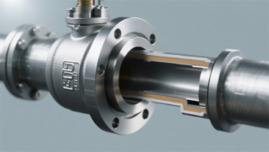
Dimensional Tolerances
The radial physical clearance between the outer diameter of the metal support ring of an API 6D pipeline ball valve and the inner diameter of the body installation cavity is maintained between 0.12 mm and 0.28 mm. The machining tolerance of CNC turning centers is strictly limited to within +0.02 mm to prevent metal scraping during assembly. A clearance parameter exceeding 0.35 mm will cause high-pressure gas, under a 1500 psi differential pressure, to extrude the backing O-ring into the metal gap and tear it.
The ISO 3601 standard requires that for static sealing O-rings used at pressures above 100 bar, their groove width dimensional tolerance must be controlled within an extremely narrow range of ±0.05 mm.
Accommodating a 1.5 mm thick PTFE anti-extrusion backup ring requires increasing the axial width of the O-ring mounting groove by 1.6 mm. The cutting tool machines a surface roughness of Ra 1.6 microns at the bottom of the metal groove, providing grip for the rubber material and preventing the seal from undergoing an axial slip of more than 0.5 mm under pressure fluctuations. The inner R-corner radius on both sides of the groove is uniformly set to 0.2 mm to 0.4 mm to eliminate mechanical stress concentration points caused by right-angle structures.
The outer diameter of the Polyether Ether Ketone (PEEK) insert is 0.08 mm to 0.15 mm larger than the inner diameter of the metal groove, achieving an interference fit assembly by applying 5 tons of axial pressure via a hydraulic press. Thermal expansion of the polymer material at 60°C will produce a volumetric deformation of about 0.05 mm; the tight fit prevents high-pressure fluids from bypassing through the back of the insert.
- Dovetail Groove Bottom Roughness: Milling operations maintain it at Ra 3.2 microns, increasing structural friction.
- Insert Inner Chamfer Dimension: The lip is machined with a 5 to 7-degree load-bearing bevel, with a dimensional deviation of ±0.5 degrees.
- Physical Protrusion Setting: The polymer face protrudes 0.3 mm to 0.6 mm beyond the metal support ring face.
- Wall Thickness Uniformity Variance: The fluctuation of polymer wall thickness across the entire circumference is strictly below 0.05 mm.
The roundness error reading of a 24-inch metal ball on a CMM must not exceed 0.012 mm. The thickness of the metal nickel plating on the ball surface is maintained at 0.075 mm, and post-plating mechanical polishing reduces the outer surface roughness to Ra 0.1 microns. When fluid thrust shifts the metal support ring 0.2 mm towards the center, this extremely low roundness error ensures that sealing specific pressure is evenly distributed across the entire 360-degree contact band.
In the ASME B16.34 specification, the centerline coaxiality deviation after assembling the left and right valve bodies is strictly required to be lower than 0.03 mm.
A coaxiality deviation greater than 0.05 mm forces the seat on one side to endure an additional 3,000 Newtons of asymmetrical shear force. The machining inclination angle of the metal-to-metal fire-safe auxiliary sealing lip on the front section of the metal support ring is set at 15 degrees, with a tolerance of ±0.2 degrees. When external environmental temperatures climb to 760°C, causing the soft insert to melt down, the metal lip contacts the ball to form a highly narrow physical blocking band just 1.5 mm wide.
Cryogenic Liquefied Natural Gas (LNG) environments require thermodynamic compensation for all machined dimensions. When the ambient temperature drops sharply from 25°C to -196°C, an austenitic stainless steel support ring with a diameter of 500 mm will undergo a physical cold shrinkage deformation of 1.45 mm. During CNC machining, an extra allowance of 0.2 mm must be added to the outer diameter of the PCTFE lip seal to offset the material’s shrinkage volume difference under cryogenic temperatures.
The cylindrical coil springs that provide preload at the back are assembled inside metal blind holes 20 mm deep. The drilling tolerance for the blind hole depth is set to ±0.1 mm, ensuring that the 36 springs evenly distributed on the support ring are compressed to the identical physical height. A depth difference of 0.3 mm leads to a 15-Newton variance in the thrust output from a single blind hole, destroying the mechanical parallelism of the seat’s entire end face.
- Blind Hole Center Position Tolerance: The center distance tolerance between two adjacent spring blind holes is kept at ±0.05 mm.
- Spring Alloy Wire Diameter Error: The batch variance of drawn wire diameter is below 0.01 mm.
- Support Ring Face Parallelism: The tilt error between the front and rear parallel metal faces does not exceed 0.02 mm.
- Initial Free Length of Springs: During incoming inspection, length deviations are strictly limited to a range of ±0.5 mm.
In harsh conditions involving massive amounts of quartz sand, the ball and seat contact faces undergo High-Velocity Oxygen Fuel (HVOF) thermal spray treatment. The spray thickness of the tungsten carbide alloy coating is precisely controlled between 0.15 mm and 0.25 mm. Coating thickness below 0.12 mm cannot resist mechanical peeling caused by fluid erosion, while thickness above 0.30 mm is prone to internal micro-cracking under 3000 psi differential pressure impacts.
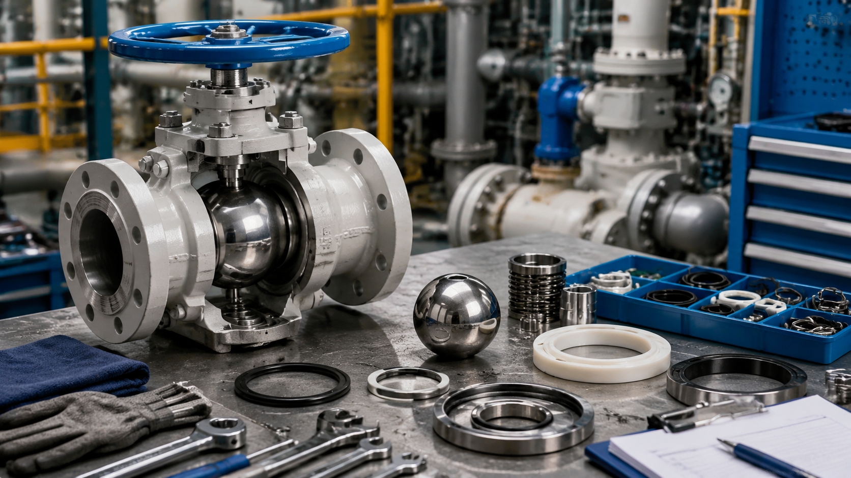
When utilizing a hard-sealed structure, the metal support ring and ball must be manually mate-lapped using 800-grit silicon carbide lapping paste prior to final assembly. The lapping process grinds off microscopic metal peaks extending 0.01 mm above the coating surface. Inspection light bands show a metal contact width on the sealing face maintained between 3.5 mm and 5.0 mm, achieving a mirror finish with a surface roughness of Ra 0.05 microns.
Seal Material
When pressure is at Class 900 (approx. 15.3 MPa) or below, soft seal materials like Devlon V-API can maintain closed micro-pores, achieving the ISO 5208 Rate A bubble-tight zero-leakage standard;
When operating temperatures exceed 260°C, or when pipeline fluids contain solid particles larger than 50 microns in diameter, polymer materials experience permanent creep. In such cases, they must be replaced with HVOF-sprayed tungsten carbide metal hard seats with a surface hardness of 72 HRC.
Polymer Soft Seals
When API 6D pipeline ball valves process fluid media from Class 150 to Class 2500, the physical and mechanical properties of the polymer materials show a quantified correlation with the system leakage rate. Engineering often uses the ISO 5208 Rate A test to verify the zero-leakage standard, where polymer seats fill microscopic surface roughness through elastic deformation at the contact interface.
Pure Polytetrafluoroethylene (PTFE) has its molecular chains completely surrounded by fluorine atoms, with a friction coefficient as low as 0.04. At room temperature and within the -46°C to 200°C temperature range, PTFE exhibits extreme inertness to most chemical solvents. When applied pipeline pressure exceeds Class 300 (approx. 5.1 MPa), pure PTFE is prone to cold flow creep, resulting in irreversible permanent compression of the material’s thickness.
To suppress cold flow deformation, manufacturing engineering typically blends 15% to 25% inorganic fillers into the PTFE matrix to enhance physical parameters by altering intermolecular bonding forces.
- Adding 15% glass fiber boosts compressive strength by 30%
- Blending 25% carbon fiber more than doubles thermal conductivity
- Mixing 5% molybdenum disulfide powder lowers dry sliding friction and wear
- A bronze powder fill ratio reaching 60% maximizes extrusion resistance
Following the addition of these fillers, the resulting RPTFE material experiences a hardness increase from Shore D 55 to Shore D 65. In Class 300 and some Class 600 lower-differential-pressure gas pipelines, RPTFE seats can withstand greater initial preloads without undergoing excessive extrusion thinning. In sour pipelines containing H2S, carbon fiber-filled RPTFE demonstrates superior hydrogen embrittlement resistance and chemical stability over glass fiber.
Facing Class 600 to Class 900 (approx. 10.2 MPa to 15.3 MPa) medium-to-high pressure gas transmission pipelines, polyamide polymers begin to replace PTFE. Devlon V-API is a high-molecular-weight polyamide developed specifically for the valve industry. Its tensile strength reaches 80 MPa at 20°C, over three times that of standard pure PTFE.
The internal porosity of Devlon V-API is extremely low, and 24-hour water absorption is strictly controlled to below 0.1%. In wet gas conditions with high moisture content, low water absorption prevents the seat from swelling and seizing the ball. Test data show that after 5000 hours of continuous operation at 100°C, Devlon’s yield strength drops by no more than 8%.
In gathering pipelines at high-pressure gas wells or compressor outlets, network pressure frequently drops abruptly, causing severe physical damage.
- An ambient pressure drop exceeding 2 MPa per minute triggers rapid expansion
- Free gas trapped inside the polymer’s micropores instantaneously expands in volume by hundreds of times
- Visible blistering or microcracks emerge on the material’s surface
- The NORSOK M-710 standard requires materials to pass cyclic decompression verification
When the system design pressure climbs to Class 1500 (approx. 25.5 MPa) or even Class 2500 (approx. 42.5 MPa), conventional polymers fracture under shear stress. Polyether Ether Ketone (PEEK) becomes the preferred polymer material for managing extreme differential pressures.
PEEK has a glass transition temperature of 143°C and a melting point up to 343°C. It maintains a compressive strength above 50 MPa under continuous 260°C operating conditions. PEEK achieves a hardness of Shore D 85; it is highly resistant to scratching, even in fluids containing fine solid particles.
High thrust setting requirements typically mandate an increase in Belleville spring compression by 15% to 20%, ensuring that even under very low pipeline pressures, PEEK seats can form sufficient initial intercept specific pressure with the ball surface. Beyond high temperature and high pressure, Liquefied Natural Gas (LNG) pipelines involve ultra-low temperature environments down to -162°C and -196°C. Cryogenic temperatures freeze molecular chains, causing standard polymers to entirely lose elasticity.
Polychlorotrifluoroethylene (PCTFE, trade name Kel-F) introduces chlorine atoms on its side chains, disrupting complete molecular symmetry, thus retaining faint elastic recovery capabilities even at -196°C. PCTFE’s compressive strength at ultra-low temperatures surpasses 120 MPa, vastly outperforming conventional pure PTFE.
The enhancement of material compressive limits is accompanied by an exponential increase in equipment frictional torque. The opening torque of a Class 150 pure PTFE ball valve is typically below 100 N·m, whereas an identically sized Class 1500 PEEK ball valve can spike to an opening torque of 800 N·m. Actuator output torque requires a 30% safety margin, and valve stem materials must be upgraded from ASTM A105 to high-strength 17-4PH or XM-19.
The turning precision tolerance for polymer seals is usually required to be within 0.02 mm. If the surface roughness Ra value exceeds 0.4 microns, high-pressure gas will slightly permeate through machining tool marks. During assembly, Lip Seals are often embedded into the back of the seat, utilizing a V-spring made of Elgiloy alloy to provide permanent energization.
When fluid pressure falls below 0.5 MPa, spring tension forcefully props open the PTFE jacket, compensating for the stress relaxation caused by long-term compression of the polymer. Above 5 MPa, the fluid’s own pressure enters the V-shaped cavity, generating a self-sealing effect. Based on cross-disciplinary calculations in fluid mechanics and materials science, engineers use software to simulate the material expansion coefficients in specific temperature fields to guide the tolerance fit design for valve components.
The ASTM D4894 specification governs the physical parameters of pure PTFE resin, mandating that its tensile strength must not be below 25 MPa. Manufacturers mold resin powder via a sintering process at 370°C, strictly controlling the cooling rate to within 20°C per hour to reduce internal residual stress. Rapid cooling causes the material’s crystallinity to drop below 50%, resulting in extremely unstable dimensional shrinkage rates.
Prior to final valve assembly, operators must measure the concentricity of the seat’s inner and outer diameters in a cleanroom environment. If the concentricity deviation exceeds 0.05 mm, effective conformity on a microscopic level becomes impossible. When working fluids contain methanol or aromatic hydrocarbon solvents exceeding a 10% concentration, conventional polyurethane materials undergo severe physical swelling.
Metal Hard Seals
When pipeline media continuous operating temperatures surpass 260°C, or when fluids carry quartz sand particles larger than 50 microns in diameter, polymer seats completely lose their structural resistance to compression. API 6D ball valves must employ metal-based isolation components with a surface hardness reaching over 68 HRC to resist wear.
The pipeline velocity in refinery hydrocracking units usually reaches 20 m/s, where media containing catalyst powder impact internal valve intercept surfaces with an initial differential pressure of 60 MPa.
Manufacturing engineering typically selects ASTM A105 carbon steel or 316 stainless steel as the substrate, coating the surface with an ultra-hard alloy layer ranging from 0.15 mm to 0.25 mm thick.
To ensure tight adhesion between the alloy coating and the substrate surface, factories widely adopt the High-Velocity Oxygen Fuel (HVOF) thermal spray process. Oxygen and aviation kerosene ignite upon mixing in the combustion chamber, generating a high-temperature jet with velocities up to 1000 m/s to 1200 m/s.
- The flame temperature during spraying reaches 3000°C
- Tungsten carbide powder is accelerated to 800 meters per second to strike the substrate
- The deposited coating’s porosity is strictly controlled to below 1%
- The mechanical bond strength between coating and substrate exceeds 70 MPa
In environments with maximum working temperatures up to 400°C, powder with a ratio of 88% tungsten carbide (WC) plus 12% cobalt (Co) is heavily applied, yielding a stable molded coating hardness within the 70 to 72 HRC range.
The addition of cobalt imparts specific fracture toughness to the tungsten carbide matrix, preventing brittle flaking of the coating whenever the valve closure generates a 1500 N impact force.
When pipeline operating temperatures climb further to 500°C to 600°C, tungsten carbide suffers severe decarburization and oxidation in oxygen-rich or acidic environments. Coatings sprayed with a mixture of 75% chromium carbide (Cr3C2) and 25% nickel-chromium (NiCr) alloy emerge as the alternative for high-temperature settings.
The surface hardness of chromium carbide generally rests between 60 to 65 HRC, slightly lower than tungsten carbide, but it forms a dense protective oxide film in extremely high-temperature conditions. In continuous high-temperature testing, its hydrogen sulfide (H2S) corrosion rate amounts to less than 0.02 mm per year.
- Following HVOF spraying, ball surface roughness typically sits above Ra 5.0 microns
- Initial grinding requires diamond abrasive belts with a 400-mesh grit
- Upon entering the fine grinding phase, it transitions to 800-mesh boron carbide lapping paste
- polishing must achieve a mirror finish below Ra 0.1 microns
Once surface roughness meets the standard, the manufacturing shop must mate-lap the ball with its corresponding metal seats. Assembly workers apply lapping medium on the contact surfaces, running specialized machine tools continuously in a figure-8 trajectory for over 48 hours.
The lapped ball and designated seats form a unique matching curved surface, compressing true roundness deviation to within 0.01 mm. Swapping positions during assembly is strictly prohibited, otherwise leakage volumes will magnify by more than 10 times.
During hydrostatic testing under ANSI/FCI 70-2 specifications, the allowable water seepage metric for Class V is rigorously calculated at 0.0005 ml per inch of nominal pipe size per psi of differential pressure per minute.
For more stringent natural gas pipelines, factory acceptance testing generally adopts the ISO 5208 Rate B pneumatic test. Under a Class 900 (approx. 15.3 MPa) nitrogen hold pressure, the permissible gas seepage rate per millimeter of nominal diameter is restricted to 0.01 cubic centimeters per second.
- To maintain initial metal face preload in the absence of system pressure
- The Inconel 718 wave springs situated behind the seat must bear high loads
- The spring compression stroke is commonly limited between 1.5 mm and 2.0 mm
- The spring’s modulus of elasticity remains above 200 GPa even at 200°C
Thrust exerted by the springs plus dry friction on the metal surfaces causes equipment operational resistance to skyrocket. The opening torque of an equivalently sized Class 600 metal-seated ball valve typically sits around 1200 N·m, three times that of its polymer-sealed counterpart.
High-torque operating conditions demand stronger shear resistance from the valve stem material. ASTM A564 17-4PH precipitation-hardening stainless steel hits a yield strength of 725 MPa, preventing stem torsional deformation or fracture when the actuator operates at full load.
In high-speed fluid networks loaded with solid-phase particulates, inadequate metal surface hardness incites severe wire-drawing erosion. When high-speed fluid under a 0.5 MPa pressure differential traverses a tiny sealing gap, local velocities instantly hit sonic levels.
Sonic fluids effortlessly shred any metallic obstacle possessing a hardness under 40 HRC. At Class 1500 level (approx. 25.5 MPa) natural gas injection wellheads, untreated 316 stainless steel seats suffer total failure and are scrapped within 72 hours of commissioning.
- Stellite 6 cobalt-based alloy utilizes the Plasma Transferred Arc (PTA) welding process
- Weld overlay thickness generally hits 2.0 mm to 3.0 mm
- Hardness is maintained between 40 to 45 HRC, capable of severing impurities up to 2 mm in diameter
- Thick overlays suit crude oil gathering systems containing large sand and gravel particles
Non-Destructive Testing (NDT) engineers must use Penetrant Testing (PT) to scan sealing faces in a darkroom; crack indication lengths exceeding 1.5 mm trigger immediate rejection.
Acidic corrosive liquids in the pipeline network permeate through microcracks along metal grain boundaries, causing chunks of the alloy coating to detach under alternating stresses, devastating the equipment’s flow isolation capacity.
Upon completing assembly, API 6D compliant equipment must undergo high-pressure water circulation flushing on a test stand. Residual diamond lapping paste particles left in the body cavity will inflict secondary physical scratches on the seat upon initial valve opening if not fully flushed out.
Engineers strictly quantify the equipment’s online maintenance schedule as well. In natural gas flow conditions running at 30 meters per second, the projected wear life of the tungsten carbide hardened layer is typically 50,000 open/close cycles, after which the microscopic gap rate climbs exponentially.
- Vibration frequency and amplitude in the operating environment affect metal contact face stability
- When pipeline vibration frequency reaches 60 Hz and displacement exceeds 0.5 mm
- High-frequency fretting friction between metal seal faces induces surface fatigue spalling
- Equipment foundation flanges require installation of 10 mm thick damping rubber gaskets
The equipment’s resistance to hydrogen sulfide and cracking must be endorsed by the NACE MR0175 standard specification. When H2S partial pressure in the fluid exceeds 0.0003 MPa, substrate Rockwell hardness is capped at a maximum of 22 HRC to prevent catastrophic rupture induced by Sulfide Stress Cracking (SSC).
The physical matching between high-hardness coatings and low-hardness substrates tests the compatibility of their thermal expansion coefficients. If the linear expansion coefficients of the two vary by more than 15%, the coating faces a risk of physical delamination caused by disparate shrinkage rates under extreme freezing conditions where temperatures plunge to -46°C.
Elastomeric Auxiliary Seals
Fugitive emission leakage rates for API 6D pipeline ball valves are determined by polymer O-rings and molded seals installed in body flanges, stems, and behind seats. In Class 600 (approx. 10.2 MPa) and higher natural gas grids, gas molecules exhibit extreme permeability on a microscopic scale.
When system methane partial pressure exceeds 5.0 MPa, the gas begins diffusing en masse into the polymer chain network pores of synthetic rubber, reaching solubility equilibrium. When pipeline pressure drops abruptly at a rate greater than 2.0 MPa per minute, the volume of high-pressure gas accumulated inside the rubber expands 100 to 1000 times within seconds.
Internal shear stress generated by expanding gas vastly outweighs the tensile strength of regular rubber, which is typically 15 MPa. Minute bubbles visible to the naked eye rapidly form on the surface and interior of the polymer, eventually developing into physical tearing fissures deeper than 2.0 mm; the industry defines this as Anti-Explosive Decompression (AED) failure.
- Boosting the acrylonitrile content of Hydrogenated Nitrile Butadiene Rubber (HNBR) beyond 36% increases resistance to gas permeability
- Fluororubber (FKM) submitted to special vulcanization processes sees its hardness bumped to Shore A 90 to 95
- Extreme hardness restricts physical deformation of rubber to under 5% under a 25.0 MPa pressure drop
- NORSOK M-710 specifications require materials to show no worse than grade 1 cross-sectional cracking after weathering at least 8 pressurization/depressurization cycles
Engineering applications must tailor the base polymer formulation around specific media compositions and temperature bands. When pipelines transport sour gas featuring over 5% hydrogen sulfide (H2S), ordinary Nitrile Butadiene Rubber (NBR) suffers severe crosslinking and hardening within 48 hours; Shore hardness spikes by over 15 points and elasticity vanishes completely.
High-saturation HNBR material must be deployed, wherein double bonds along the molecular chain are saturated with hydrogen atoms at levels exceeding 99%, effectively resisting chemical corrosion from H2S. In compressor outlet pipelines where temperatures scale to 150°C to 200°C, HNBR suffers thermal degradation, mandating a switch to Tetrafluoroethylene-Propylene Rubber (FEPM) or Perfluoroelastomer (FFKM).
The carbon-fluorine bond energy of FFKM reaches a soaring 485 kJ/mol; after 1000 hours of continuous high-temperature exposure at 250°C, its compression set remains under 20%. The material cost towers over 30 times that of regular FKM, generally confining its placement to the primary stem sealing area in Class 1500 high-pressure severe-corrosion ball valves.
| Material Type | Minimum Applicable Temperature | Maximum Continuous Temperature | Typical Tensile Strength at 20°C |
|---|---|---|---|
| Low Nitrile HNBR | -46°C | 150°C | 25 MPa |
| AED FKM (Terpolymer) | -29°C | 200°C | 20 MPa |
| FFKM (Perfluoroelastomer) | -15°C | 260°C | 18 MPa |
| VMQ (Silicone Rubber) | -60°C | 230°C | 8 MPa (Rarely used for high pressure) |
Extreme low temperatures likewise inflict irreversible destruction on elastomeric physical morphology. When ambient temperatures for Alaskan or Siberian pipeline networks plunge to -46°C, regular FKM crosses its glass transition temperature (Tg), converting entirely from a highly elastic state to a glassy state, characterized by elevated brittleness and a Shore hardness eclipsing A 95.
To fix cold weather external leakage issues, polymer theory formulates distinct low-temperature HNBR recipes by slashing acrylonitrile content (typically down to around 18%). Low nitrile HNBR manages to retain at least a 10% elastic rebound rate even at -46°C, assuring valves dodge initial leaks during freezing pump startup phases.
As temperatures slide further to the -162°C realm of Liquefied Natural Gas (LNG), all recognized synthetic rubbers fail to hold elastic structures. Engineering design scraps O-rings entirely, moving to Lip Seal assemblies comprised of polymers merged with metal springs.
The outer shell of lip seals relies heavily on PTFE laced with 15% carbon fiber and 5% molybdenum disulfide; machined wall thickness usually slims down between 0.8 mm and 1.2 mm. Inserted inside is a U-shaped or V-shaped energizing spring built from Elgiloy cobalt-chromium-nickel alloy.
- Springs are pre-compressed by 15% to 20% of their stroke during assembly to render constant thrust
- The tensile strength of Elgiloy alloy escalates beyond 2000 MPa at -196°C
- Even under hyper-cold conditions, springs blast the PTFE shell with over 50 N/mm of linear load
- Spring tension offsets dimensional shrinking of high molecular polymers under cryogenic cold
Beyond O-rings, stem fugitive emission designs commonly layer on three to five sets of V-ring Packing (PTFE). In rigorous ISO 15848-1 certification tests, valves must execute tens of thousands of mechanical on/off cycles under both ambient and design temperatures.
The supreme leakage tier Class AH dictates that, monitored by helium mass spectrometers, leakage rates surrounding the stem must not breach 1.0×10^-5 mg/(s·m) per second. Engineers compensate for live load losses by loading multiple Belleville spring washers atop the packing gland to provide sustained action to the V-packing.
Initial compressive force from the Belleville springs sits mapped between 6.0 MPa and 8.0 MPa, automatically coping with media pressure waves along with 0.1 mm to 0.5 mm wear gaps emerging from drawn-out packing friction. High-pressure valves positioned at Class 900 and above mandate fire-safe auxiliary seals along body flange joints.
API 607 fire test protocol binds equipment to burn inside a 750°C to 1000°C inferno for 30 minutes. Rubber O-rings completely carbonize and fail within the primary 5 minutes; thus, a flexible graphite spiral wound gasket or pure graphite ring featuring a 3.0 mm cross-sectional thickness is pre-installed inside the flange groove.
Expanded graphite scales a thermal limit touching 600°C (in oxidizing environments) or 3000°C (in non-oxidizing settings), surviving polymer burnout to continue guarding the sealing barrier via residual preload from flange bolts, choking external leakage beneath 400 ml per minute.
Across the assembly floor, all AED O-rings face mandatory coating with compatible synthetic silicone grease or PTFE-based lubricant prior to dropping into stem or seat grooves. Dry friction assembly prompts tiny surface scratches merely 0.05 mm deep, fueling micro-leaks generating over 20 bubbles per minute during 10.0 MPa nitrogen tests.
Pressure Balance
Framed from the perspective of field operations, for every 1°C jump in temperature fueled by external sun exposure or heat tracing systems, internal pressure for closed liquid hydrocarbons stranded inside the cavity of a trunnion mounted ball valve shoots up by roughly 105 psi (7.2 bar).
As ambient temperatures mount from 20°C to 50°C, the actual cavity pressure inside a Class 600 valve effortlessly shatters its maximum allowable working pressure threshold.
Bereft of an API 6D sanctioned Single Piston Effect (SPE) self-relieving seat arrangement or an external relief valve, differential pressures cresting thousands of psi directly crush PTFE and adjacent soft seals, inflicting irreversible media blowouts.
Abnormal Cavity Pressurization
Stationed in either the fully open or fully closed spot, trunnion mounted ball valves seal off an enclosed ring-like zone bound by the ball, the shell interior, and dual seat rings, equating to about double the volume of the pipe diameter. Liquid hydrocarbons ferried by active pipelines, or natural gas harboring free water, get detained inside pipeline components. Bounded by thermodynamic principles, marginal creeps in external environmental temperatures force aggressive volumetric expansion upon the confined liquid.
Due to the hyper-low compressibility of fluids, micro volume shifts inside an absolutely rigid finite compartment convert instantaneously into mammoth outward thrust against the ball and inner shell lining. During surface-exposed high-temperature oil pipeline tests executed in North America’s Permian Basin, day-to-night temperature gaps universally span over 30°C.
Tested thermal expansion coefficients for conventional crude oil hover between 0.0007 and 0.001 per degree Celsius. Inside a Class 300 valve jammed with crude oil, every 1°C increment pumps fluid pressure inside the closed chamber up by roughly 75 psi to 105 psi. Assuming ambient midnight temperatures at 15°C alongside baseline pipeline pressure at 500 psi, once midday solar roasting propels the metal shell temperature up to 45°C, absolute pressure inside the chamber wildly inflates past 2500 psi.
Pitted against mandatory data caps placed on flange joints and shell strength mapped by ASME B16.34 standards, the peak safe load pressure for a Class 300 carbon steel shell at ambient temperatures merely hits 740 psi. Factory hydrostatic testing limits are rigidly frozen at 1125 psi as well. An abnormal pressure surge of 2500 psi brutally eclipses the tensile yield bounds of the flange connecting bolts. Relentless internal fluid thrust compels the joining studs into dozens of microns of plastic elongation.
Before outer shell fasteners yield, soft sealing rings charged with arresting fluid incur irreversible physical demolition first. Polymer seal ring tensile strength and anti-creep marks suffer freefall decay under overload pressure gaps. Diverse materials show distinct physical data boundaries concerning failure nodes amid extreme cavity pressure:
- PTFE (Polytetrafluoroethylene): When bracing against differential pressures crossing 1500 psi, overt cold flow deformation transpires, squeezing the stressed zone aggressively into the micro gap separating the seat ring and the metal ball.
- RPTFE (Reinforced Polytetrafluoroethylene): Infusion with glass fiber heightens the compressive threshold, yet continuous exposure to 2000 psi gaps triggers permanent loss of the material’s elastic resilience.
- FKM (Fluororubber) O-rings: Overload pressure violently severs the rubber molecule crosslinks, launching Anti-Explosive Decompression (AED) failure or generating multi-millimeter physical tears.
- Devlon V-API: Despite stellar yield strength stats, once cavity pressure obliterates the 3000 psi ceiling, mammoth thrust cements the seat squarely into the metal ball’s face.
Encountering high-pressure seizing out in the field, if operators forcibly trigger the pneumatic actuator or ply extension torque wrenches to power through opening the valve, the instantaneous torque spikes instantly shear the anti-shear pin connecting the stem to the ball. Scouring offshore platform operational archives from the North Sea, rogue torque issued by actuators has literally twisted 2-inch diameter 17-4PH high-strength stainless steel stems in half.
Clause 5.8 of the API 6D standard wields a mandatory rule: involving liquid fluid pipelines, hardware configurations must equip a Single Piston Effect (SPE) seat pair to secure automated physical offloading of overpressure. The SPE seat ring rests on the geometric design of piston contact area disparity, harnessing differential pressure innate to the fluid to yield reverse repulsive thrust. Once enclosed cavity pressure surges to a zone 1.1 to 1.33 times higher than baseline upstream or downstream pipeline pressure, internal liquid thrust conquers the preload issued by the spring pack sitting behind the seat.
A code-compliant SPE relief sequence generally clocks in at just 2 to 5 milliseconds, evicting a heated expansive liquid volume usually tallying under 10 milliliters. Once this marginal drop of liquid hydrocarbon flushes into the linked low-pressure pipeline, interior cavity pressure crashes back to absolute parity with the mainline. The moment differential pressure zeroes out, dozens of cylindrical coil springs forged from Inconel X-750 corrosion-resistant alloy shove the seat ring flush against the ball face in mere milliseconds.
Particular operational protocols governing transnational gas compressor stations blatantly decree that valves must showcase DIB-1 class dual isolation safeguards; dual Double Piston Effect (DPE) structure seats cap both ends of the line. The physical geometric design backing DPE guarantees that cavity high pressure solely shoves the seat even closer to the ball, decisively barricading any automated outbound fluid escape route. Site construction documents enforce mandatory drilling through the mid-section of the cast shell to graft on an external Thermal Relief Valve (TRV).
Mapping external relief valve parameter settings and pipeline plumbing demands, European and American pipeline engineering adheres to the following exact data points:
- Cracking Pressure Setting: Calibration involving nitrogen or clean water is mandatory before shipping, locking the cracking value precisely between 1.1 and 1.33 times the maximum allowable working pressure amid a 100°F environment.
- Discharge Orifice Size: Pipe diameter sizing for the valve body drain hole generally rests at 1/2-inch or 3/4-inch, rendering ample cross-sectional area to handle the fractional flow rates tied to liquid thermal expansion.
- Metal Alloy Material: Internal sensing springs and sealing contacts exposed to H2S environments are mandatorily fabricated using 316L stainless steel or Incoloy 825 anti-corrosion alloy.
- Eco-Emission Routing: The relief discharge port must hook seamlessly into the site’s Closed Drain System utilizing NPT high-pressure threaded pipe fittings.
Seat Pressure Relief
Once the valve traps fluid in the fully closed or completely open position, expanding volumes of trapped liquid hydrocarbons cast thrusts breaching 2500 psi as exterior heat climbs from 15°C up to 45°C. Hydrodynamic engineering under the API 6D standard commands that Single Piston Effect (SPE) seats must autonomously purge liquid toward the low-pressure piping the second internal pressure breaches targeted thresholds.
Contact area ratios sketched by engineers onto blueprints usually anchor between 1.15 to 1 and 1.25 to 1. The minute cavity fluid pressure matches 1.33 times the foundational upstream pressure, surplus fluid thrust thoroughly subdues the Inconel X-750 coil spring preload. Hydraulic force pushes the metal seat ring back off the ball surface by roughly 1.5 to 3.0 millimeters, crafting an exceedingly tight annular discharge slit. Negligible drops of liquid media surge along this slit into the pipeline, wrapping the full physical discharge procedure up within 50 milliseconds.
- Spring Thrust Bleed: As cavity pressure hits 1.1 times the rated working pressure, the cluster of 30 to 50 cylindrical springs planted behind the seat registers an initial 0.5 mm compression.
- O-ring Displacement: Coping with an 800 psi pressure gap, the backing seal ring shaped from PTFE or FKM slides 0.2 mm along the body groove.
- Fluid Jet Flow Rate: Liquid hydrocarbons jetting through a 3 mm slit can log momentary speeds of 15 m/s, yielding discharge volumes mostly shy of 20 milliliters.
- Pressure Drop Recovery Point: The split second cavity pressure plummets to identical alignment with pipe pressure, thrust from the gap is negated, and spring clusters kick the seat back to surface mating within 2 milliseconds.
North American gas network operating codes forcefully rule that relief valve interface dimensions must not dip below the 1/2-inch NPT thread baseline. Pre-shipment calibration rigidly aligns the cracking value for the 316L stainless steel springs sitting inside the thermal relief valve to 1.1 times the valve’s max allowable working pressure.
| Relief Mechanism Classification | Physical Response Delay | Discharge Cross-Sectional Area Ref. | API 6D Factory Verification Test Pressure | Commonly Applicable Fluid Media |
|---|---|---|---|---|
| SPE Self-Relieving Seat | Auto triggers between 10 to 50 ms | Pipe circ. multiplied by 2 mm gap | Water pressure at 1.1 to 1.33x rated pressure | Crude or NGL carrying high expansion ratios |
| DPE External Safety Valve | Mechanical spring pops at 100 to 250 ms | Internal drainage bore typically 0.25 inch | Air pressure at 1.1x rated working pressure | Compressed Natural Gas or high-pressure gas/liquid flow |
| Rupture Disk | Metal membrane tears under 5 ms | Matches 1 to 2 inch full bore flange flow | Pre-set at 1.5x failure limit of rated pressure | Hyper-destructive frigid polar pipelines |
Test technicians pump pure water laced with fluorescent dye into the enclosed chamber, then engage high-pressure plunger pumps to smoothly amp up the internal absolute pressure at 50 psi per second. Precision digital pressure transmitters sitting on the console instantly capture the drop-off curve. The second pressure hits the 2000 psi water pressure mark pegged to Class 600 valves, digits flashed on the screen experience an immediate plunge.
This instant metric drop confirms the seat physically yielded by 1.5 millimeters, enabling the trapped pressurized water to successfully bypass the Devlon sealing ring and purge into the unpressurized side. Addressing 36-inch massive isolation valves attached to long-haul pipelines, exponential jumps in contact area compel the array of spring clusters docked behind the seat to surpass 120 units. Huge arrays of springs push radical initial preload limits to battle potential media leakage during low-pressure operation. Massive physical girth ensures the purge gap for gigantic valves generally hovers around a mere 1 millimeter.
- Pneumatic Verification Benchmarks: Bouncing ranges for cracking pressures caught during nitrogen tests sit severely curbed by ISO 15848-1 rules to within ±5% of targeted values.
- Fluid Viscosity Variables: Confronting heavy crude oil boasting viscosity topping 100 cSt, a 2 mm discharge gap drags purge times out to 200 milliseconds, briefly permitting cavity peak pressures to outpace computed models by 50 psi.
- Material Friction Coefficient: The friction mark spanning the FKM O-ring on the outer seat ring and the carbon steel casing hovers near 0.2; as temperatures rally to 80°C, friction bloats by 15%, demanding harsher differential pressures to shift the seat.
The EPA demands that the backend of all pressure relief ports tap into closed-drain recovery systems located on-site using 3/8-inch outer diameter stainless steel pilot piping. A slight positive pressure approximating 15 psi is maintained within the discharge lines to block oxygen-rich external air from backtracking into closed grids packed with combustible gas. Hundreds of meters of recovery lines consolidate high-pressure fluids surpassing 40°C, porting them into subsurface tanks.
Board operators scoping SCADA system monitors parked inside the control room capture real-time cavity pressure fluctuations bouncing within pipeline valves thanks to 4-20mA analog signals beamed back from pressure transmitters. Following shutdowns at oil pump stations stationed across freezing outposts in Alaska, trapped hot crude hitting 60°C bleeds heat outwards. As neighboring Class 900 ball valve cavities absorb that heat, system graphs clock the entire curve showing pressure dragging upwards from 1000 psi to 2500 psi.
Pipeline Engineering
Covering the entire 800-mile crude transmission span belonging to the Trans-Alaska Pipeline System (TAPS), internal architecture attached to 48-inch mainline ball valves shapes the supreme leak barrier. Engineering tech specs insist that isolation zones crossing 12 pump stations down the route utilize an API 6D DIB-2 configuration combining upstream DPE coupled with downstream SPE.
DIB-2 Configuration (Double-Isolation-and-Bleed Type 2): A lone valve harbors two autonomous sealing faces, wherein one grants unidirectional sealing (SPE) while the other dispenses bidirectional sealing (DPE).
When pipeline crude oil temperatures rise from 15°C to 40°C driven by solar baking, 72 bars of expansion pressure generated by the trapped fluid hit the downstream SPE seat with precision. The moment spring packs incur thrust transcending 1.15 times the rated pressure, the piston face backing the SPE seat yields by a few millimeters.
A miniscule drip of heated fluid routes down the yielded opening straight into the foundational downstream piping idling at 400 psi; valve cavity pressure subsequently tanks to safety baselines in under 0.5 seconds. Inconel X-750 spring packs snap back instantly, ramming the seat securely onto the ball face again.
Staring down the hyper-pressure natural gas gathering grids rooted in North America’s Marcellus Shale tracts, supreme compressibility native to the fluid forces pipeline engineering defenses to upgrade. Operational codes impose hardline mandates enforcing dual DPE seat pairings pegged to the DIB-1 scale.
DIB-1 Configuration: Dual seats showing Double Piston Effect (DPE) behaviors bracket both valve ends; whether blasted from the interior or exterior, seats plaster themselves flush onto the ball to manifest apex-grade physical isolation barriers.
Running pressures inside gas compressor stations routinely idle between 1200 psi and 1440 psi year-round. Twin closed DPE seats aggressively lock roughly 150 cubic inches of trapped residual raw gas and condensate mixes tightly inside the cast steel housing.
Engineers are compelled to thread a nationally certified Thermal Relief Valve (TRV) into the 1/2-inch NPT tapped hole sitting midway down the flanged casing. Under ASME Section VIII vessel design doctrines, factory cracking pressure parameters mapped to this relief kit are precision-calibrated to 1600 psi.
EPA Clause OOOOa targeting Volatile Organic Compound (VOC) releases spanning pipe networks pegs a stringent 100 ppm concentration redline. Engineers hold zero clearance to blindly vent high-pressure hydrocarbons purged from valve cavities directly into ambient atmosphere.
Field Piping and Instrumentation Diagrams (P&ID) loudly spotlight 3/4-inch 3/16L stainless impulse lines rounding up all TRV discharge ports attached to mainline ball valves, piping them uniformly into a 4-inch low-pressure Closed Drain System.
Addressing fiercely corrosive crude oil pipes flooded with hydrogen sulfide (H2S) cutting across the Permian Basin, material experts benchmark stringently against NACE MR0175/ISO 15156 international metallurgy codes. Carbon steel casings hopelessly fail to fight off acidic fluid corrosion running past 50 ppm limits long term.
Build documents aggressively mandate applying Gas Tungsten Arc Welding (GTAW) methods to lay down a 3 mm thick Inconel 625 anti-corrosion overlay across flange internal bores, ball faces, and the support slots hosting seat rings.
Weld overlays require precision lapping, driving surface roughness (Ra) strictly between 0.2 and 0.4 microns. Sleek alloy contact zones not only wipe out breeding grounds for crevice corrosion, they actively slash initial breakout torque figures needed by pneumatic actuators to bust open the valve by around 15%.
Pigging Capability: Long-haul pipelines require Full Bore ball valves to mirror pipeline internal diameters flawlessly, erasing all bottleneck obstacles so that 47.5-inch outer diameter Smart Pigs can sail through cleanly at 3 meters per second.
Throughout Subsea Pipelines plunging over 2500 meters deep into the Gulf of Mexico, valves clash against external seawater hydrostatic forces roaring up to 3600 psi. Engineers strip away routine shallow-water configurations, subbing in bespoke architecture tailored purely to deep-sea realities.
Internal chambers within subsea ball valves mandate proactive filling using eco-friendly silicone oil spliced with rust inhibitors, blocking out thousands of pounds of external seawater crush depth. Remotely Operated Vehicles (ROV) deploy 1500 N·m of mechanical torque across API 17D grade rotary ports to nail down underwater isolation maneuvers.
Anti-blowout Stem setups map out hardline mechanical step metrics addressing pipeline construction. The foot of a 4-inch diameter 17-4PH high-strength stainless stem highlights a machined metal thrust shoulder measuring 0.5 inches wider than its top tip diameter.
Stem Thrust Step: Any upward launch forced by violent internal fluid pressures dead-ends straight into the bottom of the bonnet hitting this metal step; even if all 4 x 7/8-inch bolts pinning the external packing gland shear cleanly, the stem will not blow out.
Fugitive Emission Test logs executing thermal cycles confirm that even after hammering through 500 complete open/close cycles rocking from negative 46°C up to positive 200°C, shaft seals tapping dual O-rings backed by graphite fire-safe packing throttle helium leak rates down beneath 10 to the negative 6th power mbar-liters per second.

")