
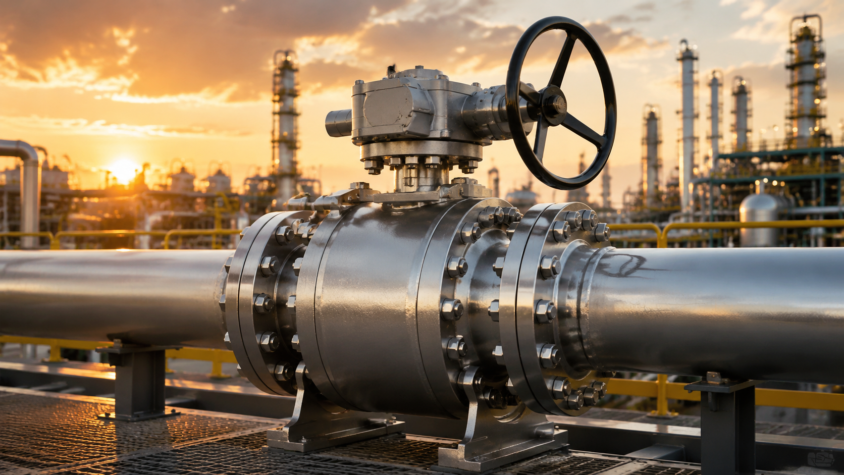
API 6D ball valves are pipeline valves designed according to the API 6D standard, mostly featuring a full-bore structure (bore diameter ≥ 95% of the pipe’s internal diameter), and are suitable for long-distance oil and gas pipelines.
Their sealing grade can reach ANSI Class 600 or above, supporting bidirectional sealing and emergency sealant injection.
Commonly used for pigging operations, the valve must be fully opened during operation to ensure the pig passes smoothly, reducing pressure drop by approximately 10%-20%.
Pipeline Applications
DBB & DIB
In the API 6D standard, the DBB structure utilizes two independent seats to achieve bidirectional interception. When the ball is in the fully closed position, upstream and downstream fluids are respectively blocked outside the ball by the seats on both sides.
If liquid or gas continuously flows out from the drain valve, it indicates that the contact between the seat seal ring and the ball surface is not tight. In a Class 600 valve with an NPS 20 diameter, this detection method can directly confirm whether the valve reaches the zero-leakage standard.
This construction, relying on a single ball to achieve two barriers, replaces early double-valve group designs. It shortens the pipeline installation space in stations by about 40% and reduces potential leakage points caused by connection flanges. DBB valves must possess an automatic relief function to prevent high pressure generated by thermal expansion of fluid trapped in the central cavity.
If the cavity pressure rises sharply because the ambient temperature increases from 15°C to 50°C, the pressure of trapped moisture inside will climb. At this time, the SPE seat structure will take effect. When the cavity pressure exceeds the pipeline pressure by about 1.1 to 1.33 times, the seat ring will be pushed away, releasing excess pressure back into the pipeline.
| Technical Parameter | DBB Standard Details | DIB-1 Technical Requirements | DIB-2 Configuration |
|---|---|---|---|
| Seat Type | Two SPE (Single Piston) | Two DPE (Double Piston) | One SPE + One DPE |
| Sealing Principle | Relies on pipeline pressure for unidirectional sealing | Relies on pipeline and cavity pressure for bidirectional sealing | Upstream unidirectional, downstream bidirectional |
| Pressure Relief Method | Automatic relief toward the pipeline interior | Requires an external safety relief valve | Automatic relief through the upstream side |
| Application Diameter | Conventional NPS 2 to NPS 56 | Critical isolation zones above NPS 4 | Metering sections above NPS 6 |
The DIB-1 model is configured with two DPE seats. Even if the upstream seat fails due to damage from welding slag or sand in the pipeline, the downstream seat can still tightly adhere to the ball by relying on the pressure within the cavity. In the API 6D test procedure, DIB-1 must undergo a high-pressure seat test from the cavity side.
For an NPS 24 specification DIB-1 ball valve, when water pressure of 1.1 times the rated working pressure is injected into the cavity, the downstream seat must maintain no visible leakage within 15 minutes. This design is often used in refined oil pipelines where mixing of media is strictly prohibited, preventing 92-octane gasoline and 95-octane gasoline from undergoing osmotic pollution at the valve.
DIB-2 combines the strengths of both. It retains the SPE seat on the upstream side, ensuring the system can automatically handle cavity overpressure. The downstream side is installed with a DPE seat as safety redundancy. In a 10.3 MPa operating environment, this asymmetric structure can reduce friction torque during operation and extend the life of the actuator.
Soft-seated seals usually adopt Devlon V-API, providing ISO 5208 Rate A grade sealing within the range of -29°C to 121°C. For acidic media containing hydrogen sulfide, materials complying with the NACE MR0175 standard must be selected.
The ball surface adopts HVOF sprayed tungsten carbide, and the coating hardness needs to reach above 1000 HV. The spray coating thickness is usually controlled at 0.2 mm to prevent coating peeling or micro-cracks in extreme temperature difference environments.
The installation environment of long-distance pipelines is extremely harsh. To prevent the valve stem from flying out under overpressure, API 6D valves must be designed with an anti-blowout stem structure. The fitting precision between the stem shoulder and the stuffing box is extremely high, usually using 17-4PH high-strength stainless steel, with yield strength exceeding 724 MPa.
Valve body wall thickness must strictly follow the ASME B16.34 calculation specification. For an NPS 30 Class 900 ball valve, its thinnest wall thickness must reach 75 mm or more to withstand bending loads generated during long-distance transportation. Valve body materials such as A694 F60 must have a carbon equivalent controlled below 0.43%.
A lower carbon equivalent ensures welding quality during field construction, avoiding cracks in the weld heat-affected zone. During the shell hydrostatic test at 1.5 times the rated pressure, the pressure-holding time is at least 30 minutes. For large-diameter valves, any visible deformation exceeding 0.1 mm is considered unqualified.
Internal fire safety of the valve follows API 607 or API 6FA standards. After undergoing a continuous fire test at 760°C to 980°C for 30 minutes, even if the PTFE seal ring is completely burned, the secondary metal seal of the valve must still limit external leakage to within 1 ml per minute per inch of seal diameter.
The selection of actuators also follows rigorous data standards. Gas-over-oil actuators are usually configured in unmanned stations in desert regions. These actuators are driven by the pipeline’s own pressure, and the equipped energy storage tanks must satisfy the ability to support 3 complete open-close operation cycles after the main power is cut off.
To reduce seat wear, torque changes during the valve opening process must be accurately recorded. The breakaway torque is usually more than 2 times the running torque.
In booster stations of long-distance pipelines, these valves are usually integrated with monitoring systems. Sensors collect pressure data 10 times per second; once a pressure drop rate of 0.5 MPa/s is detected, the logic controller will immediately trigger an emergency shutdown. Under this state, the API 6D ball valve must complete closure at a rate of 1 second/inch.
In later maintenance, the seat emergency grease injection system can solve 80% of minor internal leakage. By injecting specialized sealing grease into the check valve with a high-pressure grease gun, tiny scratches on the sealing surface are filled. This emergency measure can buy more than 48 hours of dispatching time for the repair team, avoiding sudden shutdown of the entire pipeline.
Structural Materials
API 6D valve body material selection usually refers to the pipeline steel grade (SMYS); for example, if the main transport line uses X70 steel pipe, the matching valve body should use ASTM A694 F70 forgings. The yield strength of this material must reach above 485 MPa to ensure that no permanent deformation exceeding 0.2% occurs under high-pressure creep.
For low-temperature environments of -46℃, ASTM A350 LF2 becomes the first choice, which must meet a 27 Joules energy absorption standard in low-temperature impact tests. Large-diameter NPS 48 valve bodies adopt integral forging or a three-piece structure in production to reduce weld length and improve the overall structural geometric precision.
ASTM A694 stipulates that carbon equivalent (CE) must be controlled below 0.43% to improve the success rate of field welding. If the carbon content exceeds 0.30%, in welding conditions below zero degrees Celsius, micro-cracks are very likely to be generated in the weld heat-affected zone, leading to brittle fracture when bearing 12 MPa pressure later.
Valve body wall thickness calculation is based on the ASME B16.34 standard; for an NPS 24 valve of Class 600 grade, the thinnest part of the pressure-bearing area must not be lower than 42 mm. To resist soil corrosion, the outer wall will be sprayed with a 500-micron thick heavy-duty anti-corrosion Fusion Bonded Epoxy (FBE), which must pass a 2000-hour salt spray endurance test.
As the component bearing the greatest internal force, the ball substrate is mostly selected from A105 nickel-plated (ENP) or 410 stainless steel. For acidic conditions containing hydrogen sulfide, the substrate must meet the NACE MR0175 standard, with hardness strictly limited below HRC 22 to prevent hydrogen-induced cracking (HIC) or sulfide stress cracking.
The phosphorus content of the ENP coating is usually controlled between 7% and 9%, with a coating thickness of about 75 microns. When the medium contains solid sand particles, the surface should switch to HVOF high-velocity oxygen fuel sprayed tungsten carbide, with the layer thickness increased to 0.2 mm and hardness jumping to above 1000 HV, preventing erosion wear under high flow velocity.
The bonding strength between the tungsten carbide coating and the substrate must be greater than 70 MPa. In Class 1500 high-pressure testing, after 500 frequent opening and closing cycles, if the ball surface scratch depth exceeds 0.05 mm, it will lead to leakage of more than 30 ml per minute at 25.5 MPa pressure for soft-seated valves.
The valve stem is selected from 17-4PH high-strength stainless steel, with the heat treatment state usually H1150D, and its tensile strength reaches 862 MPa. When this material bears 1.5 times the rated torque, the shear safety factor can still remain above 2.0, avoiding the risk of stem breakage caused by the actuator jamming.
Seat seal rings under Class 600 conditions mostly adopt Devlon V-API. The yield strength of this material in a 121℃ environment is 3 times higher than ordinary PTFE. In an NPS 12 valve, it can withstand a seat sealing specific pressure of 10.3 MPa without producing plastic flow, ensuring the sealing surface maintains a roughness of 0.1 microns.
PEEK (polyetheretherketone) is suitable for higher temperature 260℃ conditions, but because the material modulus is extremely high, the ball roundness requirement reaches within 0.02 mm. If the roundness deviation is too large, the instantaneous torque at the moment of valve opening will surge by 40%, possibly leading to the pneumatic actuator being unable to act due to insufficient power.
O-rings select Viton GLT or HNBR, with hardness around 90 Shore A. To prevent explosive decompression (RGD) during a sudden pressure drop from 15 MPa, the rubber seal ring must pass crude oil immersion and carbon dioxide penetration tests, with the volume expansion rate controlled within 5%.
The cavity sealing gasket adopts a spiral wound gasket of 316L stainless steel tape wound with flexible graphite. In the API 607 fire test, when soft seals are completely burned at 760℃, this metal gasket must utilize pre-tightening force to achieve secondary metal sealing, limiting external leakage to within the standard of 1 ml/minute per inch of diameter.
Valve fasteners use ASTM A193 B7 for bolts and A194 2H for nuts. For buried valves, bolt surfaces need Dacromet treatment or hot-dip galvanizing, with salt spray tests reaching 1000 hours. In Class 900 valve groups, the pre-tightening force of each bolt must reach 50% of its yield strength to offset sealing force fluctuations brought by thermal expansion and contraction.
Bolts under NACE conditions must be of B7M material, with hardness forced below HRC 22. Experimental data shows that ordinary bolts with a hardness of HRC 35 will suffer head snapping due to stress corrosion cracking within only 48 hours in a hydrogen sulfide environment, causing a catastrophic valve cover fly-out accident.
Valve grease injection valves and drain valves are all manufactured from 316 stainless steel to prevent these exposed components from failing due to environmental salt corrosion. The internal pressure of the grease injection pipeline must reach above 70 MPa; in emergency conditions, specialized sealant is injected via a manual high-pressure pump to fill mechanical scratches about 0.2 mm in diameter on the seat.
Raw materials entering the factory must check the CMTR (Certified Material Test Report), including the precise proportions of more than 10 chemical elements such as C, Si, Mn, P, S. For large-diameter key components, 100% Ultrasonic Testing (UT) and Magnetic Particle Testing (MT) are also required to ensure there are no original cracks or slag inclusions with a diameter exceeding 1.6 mm inside.
Full Bore
Dimensional Standards & Bore Alignment
Section 5.3 of the API 6D specification has rigid regulations for the internal diameter tolerance of full-bore ball valves. The minimum internal bore of the valve must perfectly match the internal diameter of the pipe under ASME B36.10M or B36.19M standards; this millimeter-level alignment error is usually controlled within 1.5mm.
| Nominal Pipe Size (NPS) | Pressure Class (Class) | API 6D Min Bore (mm) | Corresponding Pipe (Sch 40) ID (mm) | Allowable Deviation (mm) |
|---|---|---|---|---|
| 2 | 150-600 | 49 | 52.5 | -3.5 |
| 4 | 150-600 | 100 | 102.3 | -2.3 |
| 6 | 150-600 | 150 | 154.1 | -4.1 |
| 8 | 150-600 | 201 | 202.7 | -1.7 |
| 10 | 150-600 | 252 | 254.5 | -2.5 |
| 12 | 150-600 | 303 | 304.8 | -1.8 |
| 16 | 150-600 | 385 | 381.0 | +4.0 |
| 20 | 150-600 | 486 | 477.8 | +8.2 |
| 24 | 150-600 | 589 | 590.5 | -1.5 |
If the seat and the ball channel produce a step exceeding 2mm, the Reynolds number (Re) will fluctuate violently as fluid passes through.
In CNC machining centers, the concentricity error between the ball through-hole axis and the seat centerline must be limited within a 0.05mm range. When the ball is fully open, the flow path must present a regular cylinder; any radial displacement will induce vortices at the edge of the sealing surface.
Ball through-holes are usually reserved with a positive deviation margin of 0.5% to 1% in design drawings. This practice is to prevent the bore size from shrinking below the standard value after the valve undergoes micro elastic deformation under rated working pressure, ensuring the flow path is always unobstructed.
In the assembly process, the diagonal difference must be kept below 0.2mm. At the connection between ASME B16.5 flanges and the valve body, the bevel internal diameter must be customized for boring according to the actual wall thickness such as Sch 40 or Sch 80.
Precise physical dimension alignment keeps the fluid pressure drop (ΔP) at an extremely low level of below 0.01 bar. In a natural gas main line with a total length of 500 kilometers, a block valve is set every 20 kilometers. If the valve bore deviates from the centerline by 3mm, the energy efficiency loss of a single valve will increase by about 15%.
Flow path flatness is directly related to the running trajectory of a pig (PIG). Magnetic particle detection pigs on the market are equipped with high-sensitivity sensor probes; these probes’ capture precision for the distance to the pipe wall reaches the 0.1mm level.
| Pigging Equipment Type | Sensor Precision Requirement | Valve Bore Allowable Runout | Physical Impact Consequence |
|---|---|---|---|
| Mechanical Pig | +/- 5mm | < 10mm | Abnormal wear of supporting cups |
| Geometry Detection PIG | +/- 1mm | < 3mm | Collection of false deformation signals |
| Magnetic Flux Leakage (MFL) | +/- 0.1mm | < 1.5mm | Physical impact damage to sensor probes |
| Ultrasonic Leak Detector | +/- 0.05mm | < 1mm | Uneven thickness of couplant layer |
| Smart Imaging PIG | 2K Resolution | < 0.5mm | Violent shaking of the picture |
If the internal diameter of a full-bore ball valve is more than 5mm smaller than the pipe, the driving cup of the pig will produce severe extrusion deformation at the edge of the seat. According to mechanical experimental data, this extrusion leads to an increase in running backpressure of 0.5 MPa to 0.8 MPa, greatly increasing the risk of the pig jamming and stopping at the valve.
Engineers must include thermal expansion in the bore tolerance at the early design stage, ensuring the ball hole and seat remain concentric under high-temperature states. Under Class 600 grade, the radial displacement generated by the valve body under pressure may reach 0.15mm, which requires the ball support structure to possess a very high rigidity modulus.
Uneven bolt pre-tightening force during the assembly process will cause the seat ring to undergo micro-skewness. Even an angle of only 0.5° will create a physical obstruction in the originally aligned flow path, inducing single-sided fluid impact on the valve internals.
Fluid scouring the uneven inner wall at a speed of 5m/s will form a vortex zone behind the step with a length about 5 times the step height. The energy loss generated by these vortices will transform into high-frequency vibration, with vibration frequencies usually concentrated between 500Hz and 2000Hz.
| Operation Monitoring Parameter | Full-Bore Precise Alignment | Existing Reduced Bore/Step |
|---|---|---|
| Flow Velocity (v) | 5.0 m/s | Local velocity rises to 7.2 m/s |
| Vibration Amplitude | < 2.0 mm/s | Rises to 8.5 mm/s |
| Noise Level | 75 dB(A) | Exceeds 95 dB(A) |
| Maintenance Cycle | 8 – 10 years | 3 – 5 years (Seat replacement required) |
| Seat Erosion Depth | < 0.01 mm/year | > 0.15 mm/year |
Secondary backflow generated by particulate matter hitting the step will cause grooves with a depth exceeding 0.1mm to appear on the seat sealing surface within 24 months, leading the valve to lose its shutoff sealing function.
The actual measured minimum bore recorded in the API 6D certificate must be verified by a coordinate measuring machine. Procurement personnel should verify the inspection report provided by the manufacturer to ensure that the actual roundness data of the ball bore and valve body flow path meet engineering requirements.
The smoothness (Ra value) of the internal flow path of the valve body should reach 3.2μm or more, which can significantly reduce the boundary layer thickness. In a supercritical flow state where the Reynolds number exceeds 10^6, any tiny protrusion on the flow path surface will cause the friction factor (f) to rise at an exponential rate.
The internal flow path of high-end full-bore valves usually requires sandblasting or mechanical polishing to remove burrs and sand sticking from the casting process. If valve internals undergo ENP (electroless nickel plating) treatment, the plating thickness must be strictly controlled at 75μm +/- 5μm to prevent uneven plating from changing the actual bore.
Hydrodynamic Efficiency
The flow path internal diameter of an NPS 8 Class 600 full-bore ball valve is maintained at 201mm, with the flow coefficient Cv value stabilized above 8600. The flow path internal diameter of reduced-bore valves is usually only 150mm, and the Cv value will plummet to around 3200, with a loss of over 60% in fluid passage capacity. The flow path cross-sectional area remains constant from 0.031 square meters, eliminating the vena contracta as fluid enters the valve body.
Under crude oil transportation conditions with a flow velocity of 4.5m/s and a density of 880kg/cubic meter, the resistance coefficient K value of full-bore valves is usually lower than 0.1.
The K value of reduced-bore valves under the same flow rate will climb to around 0.5, producing more than 5 times the local resistance loss. This physical characteristic allows the full-bore design to exhibit hydraulic performance close to that of a straight pipe in long-distance pressure transmission systems.
A booster station equipped with 20 full-bore valves can reduce approximately 850,000 kWh of power transmission loss annually compared to a reduced-bore scheme. Calculated at an industrial electricity price of 0.75 yuan/kWh, the average annual operating cost of a single station can be reduced by about 630,000 RMB.
When fluid passes through a reduced-bore port, static pressure energy is converted into kinetic energy, and the flow velocity instantaneously increases from 5.0m/s to 8.8m/s. This velocity surge generates strong turbulent pulsations, with the Reynolds number Re skyrocketing from 50,000 to over 120,000.
High-pressure natural gas produces the Joule-Thomson effect during the throttling process; for every 1.0 MPa increase in pressure drop, the gas temperature drops by about 0.45 degrees Celsius.
The pressure drop ΔP in a full-bore flow path is maintained below 0.015 MPa, successfully avoiding the risk of gas hydrate crystallization caused by a significant drop in temperature. This temperature control stability ensures that downstream separators and dehydration units operate in ideal conditions above 15 degrees Celsius.
The internal wall roughness Ra of API 6D full-bore valves is controlled between 3.2 and 6.3 microns. When a step of more than 2mm exists in the flow path, the boundary layer thickness will skyrocket from 0.05mm to 1.2mm, inducing violent shear stress between the fluid and the pipe wall.
Low flow resistance characteristics make a positive contribution to the Net Positive Suction Head available (NPSHa) of centrifugal pumps. Installing full-bore valves at the pump suction end can increase the head margin by about 0.2 to 0.5 meters. This subtle pressure increase prevents the liquid from cavitating at 0.03 MPa absolute pressure, extending the life of the pump impeller by more than 30%.
- Class 150 Operating Parameters: For an NPS 12 valve at 2.0 MPa pressure, the full-bore pressure drop is only 0.005 bar, which is almost negligible.
- Class 900 Operating Parameters: For an NPS 6 valve at 15.0 MPa high pressure, the full-bore flow path can maintain a steady air velocity of 12m/s.
- Viscosity Influence Coefficient: For high-viscosity crude oil above 500 cSt, full-bore valves can reduce the starting shear resistance by about 40%.
Turbulence generated by fluid passing through reduced-bore valves induces high-frequency vibration, with vibration acceleration usually falling in the 10g to 15g range. Full-bore flow paths control the vibration level within the standard safety line of below 2.5mm/s.
The noise of full-bore valves in the fully open state is usually maintained at around 70 decibels. For reduced-bore valves, due to high-velocity fluid hitting the back of the seat, the noise level will soar to over 92 decibels, forcing operators to pay for expensive sound insulation covering installation.
Solid particles contained in the medium have extremely strong destructive power at a speed of 10m/s. The full-bore design allows particles to run in a straight line, with the impact angle less than 5 degrees. Secondary backflow generated inside reduced-bore valves will cause particles to repeatedly hit the ball surface at a 45-degree angle, with erosion depth increasing at a rate of 0.12mm per year.
- 20-Year Life Cycle Cost: Although the initial procurement cost of full-bore valves is 25% higher, the total O&M expense is only 40% of the reduced-bore scheme.
- System Response Speed: The low-resistance flow path keeps the pipeline cutoff time within 15 seconds, effectively reducing the peak pressure of water hammer waves by 0.8 MPa.
- Flow Measurement Accuracy: The flow state at 10 pipe diameters behind the valve is smooth, improving the measurement accuracy of ultrasonic flowmeters by about 0.5%.
The internal surface of the ball bore and the seat protection ring form a continuous physical barrier, preventing erosion of the sealing surface caused by fluid under a pressure difference of 8.0 MPa. This design allows main line valves to run stably for over 15 years in a maintenance-free state.
Pigging Operations
API 6D Full-Bore
In a 24-inch pipeline system, a Class 600 ball valve must ensure an internal bore of no less than 589 mm. This specification ensures that a smart detector weighing 200 kg passes at a uniform speed under a push of 4 MPa pressure, without being scraped by protruding metal edges.
Usually, the roughness of the internal pipe wall is treated at around 15 microns. The external diameter of the pig’s sealing cup will be 2% to 4% larger than the pipe’s internal diameter; this interference fit forms the propulsion power. When the equipment rushes into the valve at a speed of 2 meters per second, the concentricity deviation required by API 6D must be controlled within 0.5 mm to prevent cup tearing causing power leakage.
- 8 inches (DN200) bore no less than 203 mm.
- 12 inches (DN300) bore no less than 305 mm.
- 28 inches (DN700) bore no less than 684 mm.
- The slope of the wall thickness transition section is required to be less than 1 to 4.
- Flow path roundness deviation needs to be controlled within 1% of the internal diameter value.
The contact force of the cup pressed against the seat sealing surface is usually around 1.0 MPa. If the assembly clearance between the seat and the ball exceeds 2.5 mm, the cup will sink into the gap under the action of pressure difference. This will cause the driving pressure to drop from 5.5 MPa to 5.2 MPa, resulting in insufficient equipment travel power, or even stagnation near the 30-degree open position.
The probe is very sensitive to cracks larger than 0.5 mm and cannot generate violent vibration when passing through the valve. When the API 6D valve is fully open, the step difference between the internal diameter and the pipeline wall thickness cannot exceed 1.5 mm, which allows the signal-to-noise ratio of the detection signal to maintain a level above 20 decibels.
- Electromagnetic sensor sampling frequency reaches 2000 Hz.
- The hardness of polyurethane seals is around 80 Shore A.
- Seat sealing surface flatness requirement reaches 0.001 mm.
- The tensile strength of the stainless steel valve stem exceeds 550 MPa.
- The friction factor of low-torque bearings is less than 0.15.
The cavity volume of a 36-inch large-diameter valve often exceeds 1500 liters. When a pig slides into this space, the effective thrust area will change, and the flow velocity will consequently fluctuate by more than 10%. The API 6D ball valve fixes the travel trajectory of the cup through a support ring, avoiding the phenomenon of the equipment’s head dropping in a 900 mm wide channel due to its own weight.
Before the operator opens the barrel cover, it is necessary to open a 25 mm diameter relief valve to vent the cavity pressure to 0. As long as there is a 0.1 MPa pressure difference on the seal ring, the manual safety interlock cannot be unlocked, preventing high-pressure media inside from spraying out like a cannonball.
- High-pressure sealing test duration is no less than 15 minutes.
- Sealing surface roughness Ra value is controlled at 0.2 microns.
- Spring compensation amount satisfies 50,000 reciprocating opening/closing cycles.
- The impact toughness of valve body forgings must reach 27 Joules.
- The overall leakage of the valve must satisfy the ISO 5208 zero-leakage standard.
ASTM A105 carbon steel forgings, when facing fluid impact containing 3% silt, must have the annual metal loss controlled within 0.03 mm. The smooth flow path inside the valve reduces fluid vortices, preventing sulfur-containing media from depositing at the bottom 6 o’clock direction, extending the valve’s service life to over 25 years.
Every time a pig passes through a full-bore valve, the SCADA system will record a pulse signal of about 0.02 MPa. By analyzing these 10-millisecond level pressure curves, technicians can calculate the specific thickness of wax build-up inside the pipe. A successful operation can reduce the delivery pressure of a natural gas pipeline by 0.5 MPa, saving millions of kilowatt-hours of pressurization electricity bills annually.
Valve maintenance frequency is usually set to perform a full-stroke opening/closing test every 6 months. In oil pipelines with a salt content exceeding 50 mg per liter, the ball surface needs to be treated with 0.07 mm thick hard chrome electroplating. This protective layer, with a hardness reaching 1000 HV, can effectively resist high-intensity scratching from pig wire brushes after 150 km of long-distance running.
For high-pressure natural gas long-distance pipelines, the cavity pressure relief rate of the valve needs to be controlled below 0.5 MPa per minute. If pressure is released too quickly, the rubber seal ring inside the seat will bubble or burst due to the “rapid decompression effect.” RGD (anti-explosive decompression) grade seals required by the API 6D specification can withstand violent conditions from 20 MPa down to atmospheric pressure within 10 minutes, ensuring sealing performance after pigging.
Seat Structure
API 6D soft-seated valve seats are often selected from 15% glass fiber filled PTFE material, with Shore hardness usually set at around 60. For high-pressure pipelines of Class 900 and above, engineers will switch to PEEK material, which can still maintain a yield strength of 50 MPa at 150 degrees Celsius. The processing precision of the seat insert directly determines the sealing pressure; the roundness tolerance of the contact surface between the sealing surface and the ball must be controlled within 0.01 mm.
In metal-to-metal hard sealing structures, the seat base is often made of ASTM A182 F316 stainless steel, with a 0.3 mm thick tungsten carbide layer sprayed on the surface. This hardened layer’s hardness exceeds 60 HRC, which can resist fine sand grains scouring at a speed of 5 meters per second during pigging operations. The matching grinding time between the seat and the ball usually requires more than 48 hours until the optical flatness reaches 0.6 microns.
- Nylon 12 has a water absorption rate of less than 0.2%, suitable for natural gas pre-dehydration conditions.
- Stellite 6 hard alloy wear-resistant layer thickness is between 1.5 mm and 2.0 mm.
- The compression amount of the seat seal ring is set at 0.5 mm to 0.8 mm.
- Low-pressure sealing test pressure for Class 150 valves is set at 0.5 MPa.
- High-pressure sealing test must reach 1.1 times the rated working pressure.
- The O-ring groove depth tolerance at the back of the seat ring is plus or minus 0.05 mm.
In the API 607 fire test, after high temperatures of 700 degrees Celsius burn away soft seals, the seat ring moves toward the ball under spring thrust, forming a secondary metal-to-metal seal. This 0.8 mm wide fire lip can control leakage to within 1 ml per minute per inch of diameter.
When the cavity pressure rises abnormally to exceed 1.3 times the pipeline pressure, the seat will automatically leave the ball surface to achieve pressure relief. This self-relieving structure prevents physical deformation of the valve body caused by excessive cavity pressure, protecting API 5L X70 steel pipes with a wall thickness of 35 mm from damage.
| Seat Function Parameter | Measurement Index | Industry Tolerance Standard |
|---|---|---|
| Spring Pre-tightening Force | A 12-inch valve requires 24 sets of springs | Pressure error per spring set < 2% |
| Sealant Injection Pressure | 30 MPa to 45 MPa | Interface specification 1/4″ NPT or 1/2″ NPT |
| Sealing Surface Roughness | Ra 0.2 to Ra 0.4 | Scratches exceeding 0.05 mm are strictly prohibited |
| Seat Displacement | 1.5 mm to 3.0 mm | Reciprocating motion friction force < 50 Newtons |
| O-ring Compression Rate | 15% to 25% | Anti-explosive decompression grade must reach AED |
Double Piston Effect (DPE) seats push the seat tightly against the ball through the piston area difference principle, whether from pipeline pressure or cavity pressure. In this design, the seat ring’s stress area ratio is usually set at 1.2 to 1. Even if one side’s sealing completely fails, the other side’s seat can still independently bear a 10 MPa cutoff pressure, achieving a redundant bidirectional sealing design.
Wave springs or helical springs at the back of the seat are usually made of Inconel X-750 nickel-based alloy to prevent stress corrosion cracking in hydrogen sulfide environments. For a 20-inch ball valve, the total spring thrust should be sufficient to overcome the 500 Newtons static friction force generated by the ball’s weight. In the full stroke of the valve opening from 0 to 90 degrees, the spring’s stroke loss must not exceed 5% of the rated pressure.
- The strength attenuation of Inconel X-750 springs at 400 degrees Celsius is lower than 5%.
- The wire diameter precision requirement for helical springs is plus or minus 0.02 mm.
- The starting sealing pressure for a 24-inch Class 600 seat is 0.2 MPa.
- Emergency sealing grease injection frequency is usually once every 50 opening/closing operations.
- Seat drain hole diameter is generally 15 mm, used to remove 5% volume of accumulated liquid at the bottom.
When 0.1 mm solid particles damage the sealing surface and cause internal leakage, high-viscosity sealing composite material is pumped in through the external grease injection valve. The viscosity of this material is as high as 500,000 cP, which can instantly fill tiny pits on the seat surface. An annular oil groove 2 mm wide is machined on the inner side of the seat ring to ensure the sealing grease is distributed evenly over 360 degrees.
The seat assembly environment requires an air dust count of less than 100,000 particles per cubic meter. In low-temperature conditions of -46 degrees Celsius, the seat ring must undergo cryogenic treatment to eliminate internal stress generated by different material thermal shrinkage rates. If the shrinkage difference between 316 stainless steel and PEEK exceeds 0.1 mm, the sealing pair will produce a 20% torque fluctuation at low temperatures, causing the actuator to be unable to reset accurately.
Seats in high-frequency pigging pipelines will have an additional layer of dust wiper. This ring, made of polyurethane with a 90A Shore hardness, can block more than 98% of pipeline welding slag from entering the seat spring cavity. Maintenance data indicates that the service life of seats equipped with dust wipers is extended by more than 3 times compared to ordinary structures, making the valve’s mean time between failures exceed 100,000 hours.
- The radial tension of the dust wiper is set at 15 Newtons/cm.
- The opening pressure of the grease injection check valve needs to be controlled at about 0.1 MPa.
- The axial movement margin of the seat ring is usually reserved at 5 mm.
- The cavity drainage valve (Bleeder) relief diameter is not less than 1/2 inch.
- The verticality deviation requirement for the seat support ring is less than 0.03 mm.
The single weight of the seat of a large 48-inch ball valve can reach 80 kg. To support this weight and maintain a 0.02 mm sealing clearance, the seat ring usually adopts a three-point guidance structure. This mechanical support method offsets the lateral impact force generated by fluid at a flow rate of 1000 cubic meters/hour. All seat components must undergo a 150% rated pressure static life cycle test before leaving the factory to ensure that material fatigue fracture will not occur within the 30-year design life.
Double Block and Bleed Function
The Double Block and Bleed clauses in the API 6D specification mandate that the ball valve provide two independent sealing pairs in the closed state. For a 24-inch Class 900 pipeline valve, the upstream and downstream seats must each bear the full differential pressure load at a test pressure of 15.5 MPa. Cavity pressure is vented through a 1/2 inch or 1 inch relief valve at the bottom to verify that no internal leakage has occurred in the valve.
During pig launcher/receiver loading and unloading operations, the DBB structure provides secondary protection at the physical level. Before the operator opens the launcher barrel cover, the valve cavity pressure must be reduced to 0 psig. If the pressure gauge pointer rises again by more than 0.05 MPa after venting the relief valve for 5 minutes, it is determined that the upstream seat seal has failed, and performing any operation to open the barrel cover is strictly prohibited at this time.
- Relief valve interfaces often adopt 1/2″ NPT or 3/4″ NPT specifications.
- The axial movement of the seat ring is usually set between 2 mm and 5 mm.
- The surface hardness of sealing surface materials usually needs to reach above 50 HRC.
- The limit precision deviation of the actuator must be controlled within plus or minus 0.5 degrees.
- The minimum diameter of the drain hole has explicit size requirements in API 6D Table 4.
The volume of the ball valve cavity increases exponentially as the diameter increases; for a large DN1200 ball valve, the natural gas or crude oil stored in its cavity can reach several cubic meters. The DBB function allows for the recovery or release of this part of the cavity medium without emptying the entire pipeline. This independent cutoff capability provides a precise means of isolation during the investigation stage if a micro-leakage of 0.1 mm occurs in the pipeline.
In the annual maintenance of a 48-inch natural gas compressor station, technicians successfully replaced a damaged relief needle valve under an operating pressure of 8.0 MPa using the DBB function. The pressure gauge showed the cavity pressure maintained at 0, while the upstream and downstream seats firmly held back a fluid thrust totaling more than 2000 tons.
To enhance safety, the DIB-1 (Double Isolation and Bleed) structure is used for more severe conditions. Different from standard DBB, both seats of DIB-1 are of a bidirectional sealing design. When 10 MPa pipeline pressure rises to 1.3 times the rated value due to accidents like fire, the cavity pressure will push the downstream seat to fit the ball more tightly, instead of automatically relieving pressure to the downstream pipeline like a DBB seat.
The wave spring at the back of the seat is made of Inconel X-750 material to ensure that within the temperature range of -46 degrees Celsius to 200 degrees Celsius, the pre-tightening force fluctuation is less than 5%. For valves above 10 inches, 18 to 36 sets of helical springs are usually distributed, and the total thrust is sufficient to overcome the static friction force of about 300 Newtons between the seat seal ring and the valve body, ensuring low-pressure sealing.
- ISO 5208 Class A sealing requires zero bubbles at 0.6 MPa air pressure.
- Fire testing must satisfy 30 minutes of high-temperature burning in API 607.
- The anti-blowout stem structure must withstand the impact of 1.5 times the rated working pressure.
- The opening pressure of the seat grease injection system check valve is set at 0.15 MPa.
- Valve body wall thickness margin usually reserves a 2 mm corrosion allowance according to ASME B16.34.
Signals for the valve being fully open or fully closed are transmitted back in real-time through the SCADA system, with the sampling interval usually set at 500 milliseconds. If the cavity pressure sensor of the DBB ball valve still does not detect the expected pressure drop 120 seconds after the close command is issued, the logic controller will automatically trigger a level-three alarm. This digital monitoring reduces the probability of human operational misjudgment to below 0.01%.
For the integrity management of long-distance pipelines over 1000 kilometers, DBB ball valves are regarded as “pressure segmenters.” A monitoring valve room is set every 30 kilometers, and through periodic cavity pressure relief tests, the presence of 0.5 mm-level sealing surface damage caused by scaling or scouring inside a pipe segment can be located within 15 minutes.
The selection of materials is directly related to the durability of the DBB function; the geometric dimensional deformation of the ASTM A105 forged steel valve body must be controlled within 0.1% over a 25-year design life. The standard for hard chrome coating thickness on the ball surface is 0.075 mm; this high-hardness layer can prevent metal debris carried by the pig from scratching grooves deeper than 0.03 mm on the ball surface during reciprocating seat movement.
The RGD (anti-explosive decompression) performance of the seat seal ring is particularly important in frequent DBB operations. When pressure drops from 20 MPa to atmospheric pressure within 2 minutes, 90 Shore hardness fluororubber seal rings should not produce bubbles with a diameter greater than 0.2 mm inside. This material stability prevents the seal ring from detaching from the seal groove due to volume expansion, which would cause the valve to be unable to re-close after cavity relief.
- The parallelism tolerance of the seat ring is required to be within 0.02 mm.
- The protective cover of the emergency grease injection port must have IP67 grade dust resistance.
- The circumferential force for handwheel operation must be less than 400 Newtons under maximum load.
- The anti-corrosion coating thickness of the actuator is not less than 250 microns.
- The threads of the valve drain plug should be coated with molybdenum disulfide anti-seize agent.
In high-sulfur (H2S) media environments, all pressure-bearing components must comply with the NACE MR0175 standard. The hardness of seat springs and bolts must be strictly controlled below 22 HRC to prevent hydrogen-induced cracking. Even after running continuously for 180 days in an acidic environment, the free-floating capability of the seat must remain 100%, otherwise the self-adaptive sealing compensation function of the DBB will completely fail.
For large-diameter ball valves of 36 inches and above, the valve body cavity is usually provided with two sets of symmetrical drain interfaces. This layout allows the operator to still completely discharge more than 50 liters of accumulated condensate at the bottom even in an installation environment with a 15-degree slope.

")