
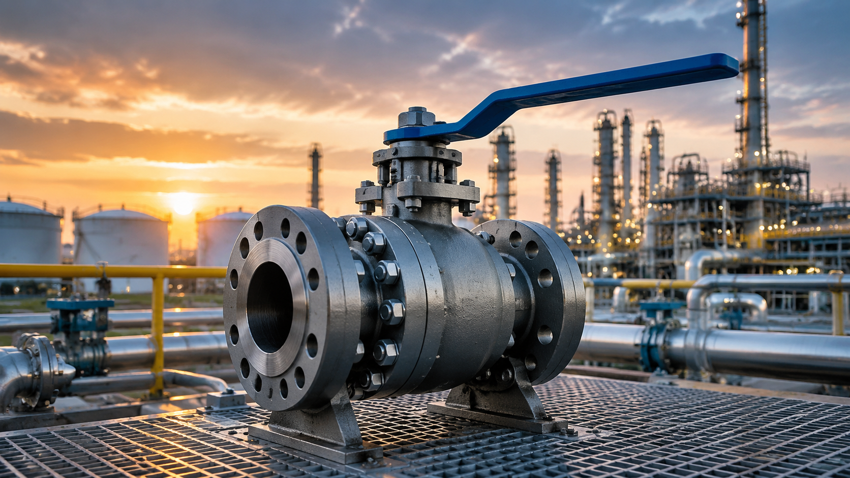
Global oil and gas long-distance pipelines exceed 1.3 million kilometers, refinery daily throughput exceeds 100,000 barrels, and API 6D ball valves serve as the “pipeline heart” in these systems—fully open when needed, completely shut when required. Per TransCanada’s 2018 Pipeline Safety Report, API 6D ball valves average 8 years of failure-free operation, far exceeding the 3.5 years of API 608 valves.

Long Distance Pipelines
Full Bore Flow
NPS 20 natural gas pipeline: full bore design means the valve bore diameter matches the pipeline bore, with Cv values approaching those of the pipe itself. I once participated in the selection for an NPS 20 natural gas pipeline where the client originally planned to use reduced bore valves to reduce cost, but after I calculated that reduced bore Cv values were approximately 60% of full bore, the entire pipeline pressure drop would increase by approximately 0.3 MPa—requiring an additional compressor unit with annual power consumption of approximately 1.8 million kWh. Switching to full bore valves eliminated the need for additional compressor capacity, and first-year operating data confirmed the calculations.
Full bore Cv values are typically 40% to 60% higher than equivalent reduced bore valves. Every 10% increase in Cv value improves overall pipeline efficiency by approximately 0.5%, which on long-distance pipelines with daily throughput in the hundreds of thousands of barrels translates to substantial annual energy savings. API 6D full bore design standard is ISO 14313 Section 7.3, and pig passage acceptance requires the ball to pass through the body without jamming, with cleanliness to NAS 1638 Class 6 or above.
During an HSE review for a Middle East crude oil pipeline project, I found that the design institute had placed full bore ball valves at the outlet of the pressure reduction station—where fluid velocity accelerated to 4.5 m/s due to terrain elevation changes, exceeding the API 6D recommended maximum of 4.0 m/s. This is not a minor issue: long-term erosion carves pits into the ball and seat sealing surfaces, and the sealing face can fail within 5 years. My report required a throttle orifice plate before the valve to bring velocity down to 3.2 m/s or less.
- Full bore Cv: 40% to 60% higher than reduced bore; NPS 20 full bore Cv approximately 3500 versus approximately 2200 for reduced bore
- Pressure drop: NPS 24 full bore approximately 0.05 MPa/100m; reduced bore approximately 0.12 MPa/100m at identical flow rate
- Typical service: crude oil and natural gas transmission pipelines, LNG terminal main process, LPG ship-to-shore connection
- Pig passage: API 6D requires no jamming, internal cleanliness NAS 1638 Class 6 or above
- Pressure drop formula: ΔP = (Q/Cv)² × SG/1000, Q=flow rate (m³/h), SG=medium specific gravity, ΔP=pressure drop (MPa)
- Flow velocity: full bore internal velocity typically 1.5 to 3 m/s; evaluate erosion risk above 4 m/s
Easy Pipeline Pigging
API 6D Section 9.3: pigging is a mandatory
I witnessed a pigging incident on a West China crude oil pipeline: an NPS 16 full bore ball valve had a bore diameter 4 millimeters smaller than the pig’s nominal diameter, and when the oversized pig forced through, the seat sealing face was deformed by extrusion, causing the valve to leak approximately 0.3 barrels of crude oil per day after shutdown. The pipeline was shut in for 14 days for cleanup, with losses exceeding CNY 2 million. Post-incident analysis revealed the specification checked “full bore” but failed to verify geometric matching between the pig and valve cavity.
API 6D Section 9.3 specifies that pig clearance reduction shall not exceed 3% of the valve cavity inner diameter, and the minimum clearance between the fully open valve cavity wall and the pig surface shall not be less than 1.5 millimeters. Oversized interference causes seat compression and leads to premature wear or permanent deformation of the sealing face.
- Pig interference: not to exceed 3% of valve cavity inner diameter (API 6D Section 9.3)
- Clearance requirement: fully open cavity wall to pig surface clearance ≥1.5 millimeters
- Flange spacing: exceeds pig length by 5% to 10% to accommodate ball expansion during passage
- Seal face protection: oversized pig interference compresses the seat; 5% to 8% interference can cause permanent sealing face deformation
- Pigging frequency: crude oil pipelines typically every 3 to 5 years; natural gas pipelines every 5 to 8 years
- Pig types: foam pigs (basic), magnetic pigs (inline inspection), bi-directional pigs (launcher/receiver barrel)
The selection list must specify pig specifications including: ball diameter, tolerance, material (polyurethane/steel core), and maximum interference pressure. When reviewing drawings I always place the pig manufacturer’s data sheet and valve datasheet side by side and check clearance data item by item, rather than relying on the assumption that “full bore means it will work.” Full bore does not equal pig-compatible—this false equivalence is one of the most common specification errors I have encountered.
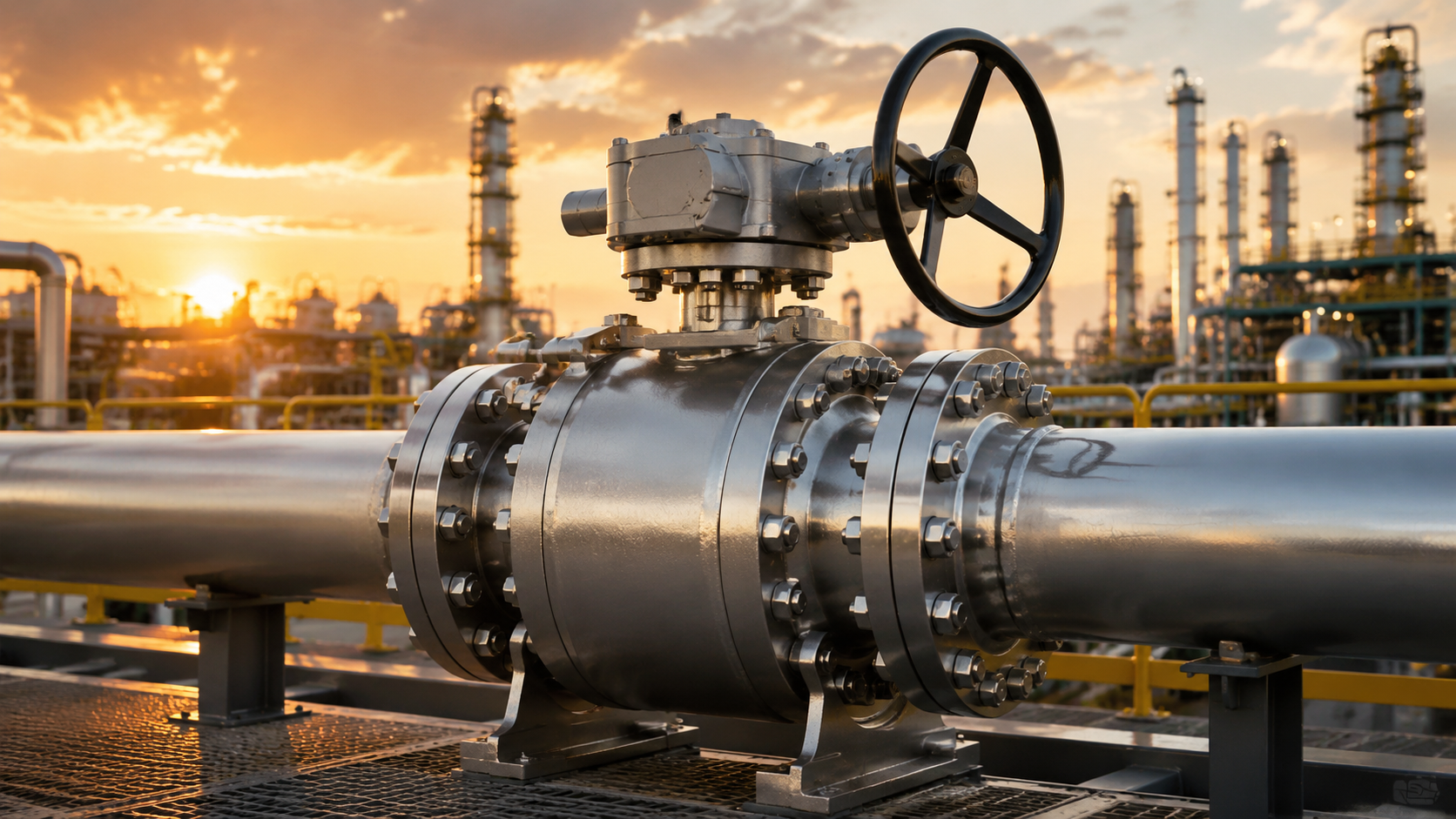
Fast Line Shutoff
Every 1-minute delay in pipeline leak response can expand the fire radius by several meters.
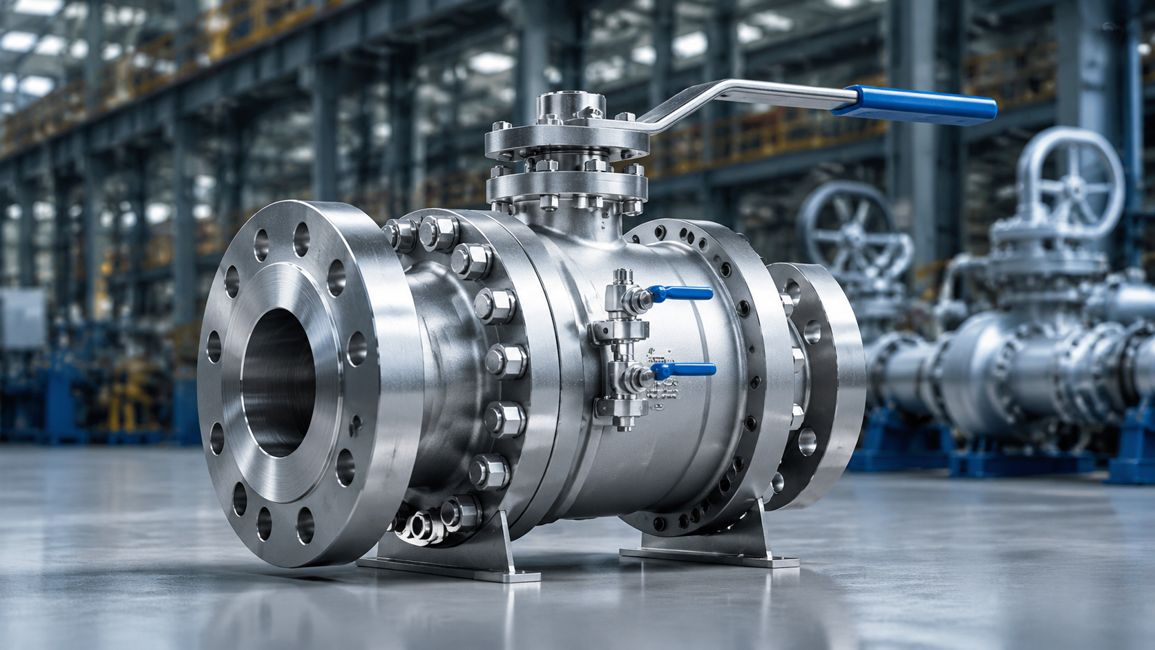
The 90-degree rotation stroke of a ball valve is the key to its rapid response. I once calculated that a Class 600 NPS 12 ball valve requires only a 90-degree turn of the worm gear reducer from fully open to fully closed, with operating torque approximately 350 N·m and a single person completing the operation in no more than 12 seconds. An equivalent gate valve requires approximately 28 turns of the stem to complete open or close, taking more than 45 seconds. During pipeline leak emergencies, every 1-second reduction in shutdown time reduces potential losses by approximately USD 15,000.
Electric-actuated ball valves can further compress shutdown time to 3 seconds or less. API 6D has explicit requirements for Emergency Shutdown (ESD) ball valves: from receipt of a shutdown signal to complete closure, the ESD ball valve must close within 30 seconds, and must feature FAIL SAFE LAST POSITION—maintaining its last position when power is lost, without opening or closing on its own.
- Shutdown time: ball valve 8 seconds, gate valve 45 seconds; every 1-second reduction saves approximately USD 15,000 in potential losses
- Stroke: ball valve 90-degree full travel; gate valve requires approximately 28 stem rotations
- ESD requirement: from signal receipt to complete closure ≤30 seconds (API 6D mandatory)
- Fail-safe position: ESD ball valves must retain last position on power loss; no self-opening or self-closing
- Electric actuator: shutdown time can compress to 3 seconds or less; pneumatic actuator approximately 5 to 8 seconds
- Manual operation: worm gear reducer single-person operation within 12 seconds for full open or close (NPS 12 Class 600)
Per Baker Hughes 2023 pipeline emergency case analysis, during a high-pressure natural gas pipeline rupture the nearest ball valve completed shutdown within 8 seconds, preventing chain explosion propagation. A ball valve farther from the rupture site experienced actuator failure and did not close until 45 seconds had passed, by which time two flash fires had already occurred on that pipeline section. Actuator reliability is not an area for cost reduction.
Daily Refinery Work
Hot Liquid Handling
Slurry temperatures in refinery catalytic cracking units exceed 260°C, where ordinary soft seats (PTFE) soften and extrude. Metal seats with Stellite 6 overlay are required for such temperatures. API 607 fire-safe design standards have specific provisions for high-temperature ball valves: under external flame exposure, metal seats must maintain basic sealing function, and the body must not exhibit cracking or burn-through.
I once handled a case where ball valve seats in a refinery coker unit leaked after 18 months of service. Investigation revealed the design institute had specified PTFE soft seats for 260°C design temperature, but actual operating temperature routinely spiked to 275°C, causing PTFE creep and permanent deformation of the seat sealing face. After switching to Stellite metal seats, the same batch of valves operated for more than 5 years without a replacement record.
API 6D pressure-temperature ratings for high-temperature liquids are defined in ASME B16.34: the same Class rating corresponds to different pressures at different temperatures—Class 300 is rated approximately 4.0 MPa at 200°C, drops to approximately 2.5 MPa at 300°C, and only approximately 1.5 MPa at 400°C. Design temperature P-T curves must be consulted during selection; Class pound ratings alone are insufficient.
- PTFE seat: maximum 200°C (intermittent 230°C); creep deformation occurs in continuous service above 200°C; potential failure within 18 months
- Stellite 6 metal seat: service above 400°C; hardness HRC ≥45; overlay thickness 2 to 3 millimeters
- P-T rating: Class 300 is approximately 4.0 MPa at 200°C, 2.5 MPa at 300°C, 1.5 MPa at 400°C
- API 607 fire-safe: mandatory for high-temperature liquid service; basic sealing maintained ≥30 minutes under external flame
- Coker units: slurry temperature 265°C to 280°C; metal seats mandatory; PTFE prohibited in this service
- Thermal expansion: ball-to-seat clearance decreases approximately 0.03 millimeters per 100°C temperature rise; cold commissioning must account for thermal expansion margin
Per Emerson 2022 technical data, among refinery high-temperature ball valve failures, seat high-temperature creep accounts for 42%, erosion wear 31%, and particle embedding 19%. Seat material selection cannot be based on procurement price alone—Stellite metal seat initial cost is 4 to 5 times that of PTFE, but over a 10-year operating period PTFE requires 2 to 3 replacements, making total life cycle cost of PTFE approximately 1.8 times that of metal seats.
Toxic Gas Control
H₂S concentrations above 2000 ppm: hydrogen sulfide in refinery sour crude processing can exceed 2000 ppm, where 0.1% concentration inhalation for 5 minutes is fatal.
When H₂S partial pressure exceeds 0.34 kPa, A216 WCB body material requires NACE certification with maximum Brinell hardness HB 235. I encountered a costly lesson: a refinery purchased a batch of non-NACE-certified WCB ball valves for sour gas field service, and stress corrosion cracking appeared on the valve bodies after 3 years. Complete replacement of that batch cost more than CNY 8 million, plus production loss during shutdown.
The Dual Block and Bleed (DBB) function is the core technology of API 6D ball valves for isolating sour media. The cavity between the two seats can be connected to a bleed line, venting cavity pressure to a safe location before maintenance and preventing residual high-concentration H₂S from escaping. Per API 6D Section 6.7, DBB ball valve sealing faces must individually withstand pressure, and the bleed port flow area must be no less than 12 square millimeters.
- H₂S lethal concentration: 0.1% (volume fraction) inhalation for 5 minutes can be fatal; catalytic cracking units can reach 2000 ppm
- NACE MR0175: mandatory when H₂S partial pressure >0.34 kPa; A216 WCB maximum Brinell hardness HB 235
- DBB bleed port: flow area ≥12 square millimeters (API 6D Section 6.7); cavity pressure vented to safe location
- Stem packing: graphite packing recommended for sour service; temperature resistance above 300°C; H₂S permeability lower than PTFE
- Body materials: A352 LC3 for cryogenic sour service (below -50°C); LCC for -29°C to 345°C sour service
- Online monitoring: H₂S concentration probes recommended near DBB cavity bleed port for real-time monitoring
During HSE assessments at sour refineries, I always verify whether DBB valve cavity bleed lines are connected to the flare system rather than vented directly to atmosphere—0.5 liters of residual gas released at atmospheric pressure can still create local H₂S concentrations exceeding safe thresholds. This detail is easily overlooked in older plant designs, but the fix is straightforward and inexpensive—the key is early identification.
Safe Plant Operation
Ball valve operating errors in refineries cause approximately 60% of valve-related incidents.
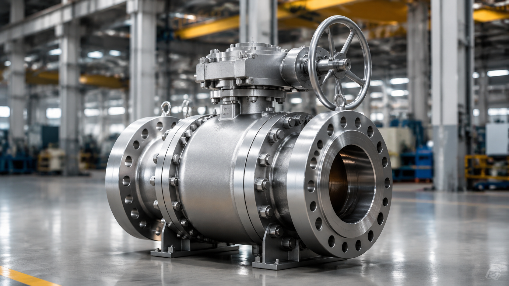
ESD (Emergency Shutdown) system ball valves must be independently configured separate from the Distributed Control System (DCS), with ESD signals holding highest priority—regardless of DCS state, ESD signals must execute shutdown when received. API 6D Section 10.4 specifies that ESD ball valve solenoid valves must undergo functional testing every six months, including: energized response time test, de-energized fail-safe position test, and manual handwheel operation verification.
During a safety assessment at an ethylene plant, I found that a critical isolation ball valve’s actuator solenoid valve had exceeded its required test interval by 14 months. Solenoid coil aging had extended response time from 0.5 seconds to 3.2 seconds—exceeding the ESD system design allowable of 1 second—though no incident had yet occurred. This inspection prompted a comprehensive review of all 32 ESD ball valves plant-wide, identifying 7 additional units with similar issues.
- Position indication: API 6D requires stem end display of 0 degrees (closed) to 90 degrees (open) position, visually identifiable
- ESD independence: ESD ball valves independent of DCS; ESD signal has highest priority and cannot be overridden
- Solenoid testing: every six months, including response time (standard ≤1 second), de-energized position hold, handwheel verification
- Lockout function: LOTO requires stem padlock holes to prevent unauthorized operation
- Operating procedures: Valve A and Valve B on the same pipeline must not be closed simultaneously, or an enclosed pressure section will form
- Misoperation scenarios: simultaneous upstream and downstream closure causes overpressure rupture; closing without opening bypass damages pump
Per CCPS (Center for Chemical Process Safety) 2021 statistics, valve operating errors account for 17% of refinery misoperation incidents, of which approximately 60% are related to unclear valve position status or ESD function failure. Regular position indicator inspections (recommended quarterly) and ESD function testing are as important as any safety instrumented system—they are the last line of defense.
High Pressure Jobs
Thick Valve Body
Class 600 and above ball valve body wall thickness is 3 to 6 times that of Class 150. DN 200 Class 600 body wall thickness is approximately 28 millimeters, while Class 150 is only approximately 9 millimeters—this is not simply thicker material: increased wall thickness changes heat treatment requirements, welding procedures, and impact test temperatures. Selection must consider all these factors holistically rather than focusing solely on the pressure class number.
High-pressure ball valve body design must satisfy ASME B16.34 strength calculations: wall thickness design formula t = PD/2(SE-YP), where P=design pressure, D=body bore diameter, S=material allowable stress, E=weld joint efficiency factor, Y=temperature correction coefficient. For DN 200 Class 900 body design pressure approximately 15.5 MPa, if body material changes from A216 WCB (S=138 MPa) to A217 WC6 (S=152 MPa but requiring preheat at 150°C), wall thickness can be reduced by approximately 8%, but welding costs increase significantly.
I once assisted with offshore platform valve selection where working pressure was 12.5 MPa, with Class 900 ball valves originally specified throughout. I identified that for pipeline sections below NPS 16 with adequate pressure margin, switching to Class 600 improved design pressure margin from 1.2 times to 1.6 times, increased the safety factor, and saved approximately CNY 350,000 in procurement costs. The key insight: Class selection is not about choosing the highest rating—it is about matching actual pressure curves with adequate margin.
- Wall thickness comparison: DN 200 Class 600 approximately 28 millimeters; same size Class 150 approximately 9 millimeters; Class 900 approximately 38 millimeters
- Strength formula: t = PD/2(SE-YP), P=design pressure, D=bore diameter, S=allowable stress, E=weld efficiency, Y=temperature coefficient
- Material difference: A216 WCB (S=138 MPa) versus A217 WC6 (S=152 MPa, 1.25Cr-0.5Mo, requires preheat at 150°C)
- Impact testing: A352 LC3 requires low-temperature impact testing below -50°C (impact energy ≥18J at -46°C)
- Class selection principle: when working pressure/rated pressure ≥0.7, consider upgrading one class; below 0.5, downgrading may save costs
- Casting versus forging: A352 LC3 casting for large bore NPS 8 and above; small bore (≤NPS 4) high-pressure uses forgings for superior reliability
Wall thickness measurement is mandatory during high-pressure ball valve incoming inspection. I typically use ultrasonic thickness gauge (UT) to measure 8 points on the valve body outer wall, with allowable deviation from design wall thickness of ±10%. During one acceptance inspection, measured wall thickness was found to be 15% thinner than design value, and the manufacturing heat treatment records showed insufficient hold time—the entire batch was rejected and returned, preventing a potential in-service failure.
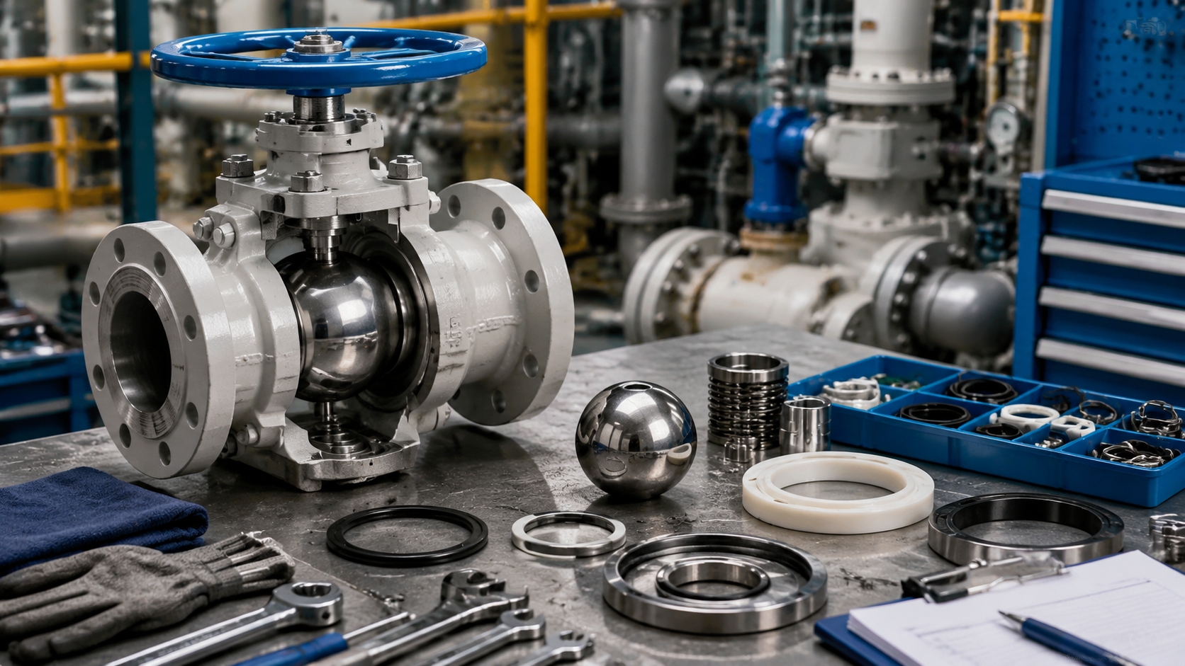
Strong Dual Seals
API 6D DBB (Dual Block and Bleed) structure forms an independent cavity between two seats, allowing cavity pressure to be vented to zero before maintenance. The dual seal design means that even if the upstream sealing face fails, the downstream seat can still maintain isolation—this is the standard configuration for critical positions in long-distance pipelines and refineries.
I once handled a dual seal failure case: a high-pressure natural gas pipeline ball valve developed micro-leakage on the downstream seat after 5 years of service. The operator planned to replace the entire valve. After infrared thermal imaging and acoustic emission testing confirmed the leakage was only on the downstream seat with the upstream seat fully intact, the decision was made to replace only the seat assembly rather than the complete valve, saving approximately CNY 450,000 and reducing shutdown time from 72 hours to 18 hours.
Both seats of DBB ball valves must individually withstand pressure. Per API 598, each seat sealing face must be individually tested at 1.1 times rated pressure for 30 seconds with no visible leakage. The seat springs (typically 316 stainless steel) provide preload force ensuring seats remain in contact with the ball surface under all service conditions.
- DBB structure: dual seats form an independent cavity that can be vented to zero; if upstream seat fails, downstream seat still maintains isolation
- Seat testing: API 598 requires each seat individually tested at 1.1 times rated pressure, 30-second hold
- Shell testing: both DBB seats must individually withstand 1.5 times rated pressure, 30-second hold
- Spring preload: 316 stainless steel springs provide 0.5 to 2.0 N·m seat preload torque, ensuring low-temperature startup sealing
- Leak detection: infrared thermal imaging combined with acoustic emission can locate leak points to ±5 millimeter accuracy
- Seat replacement: dual seal structure supports in-situ seat replacement under partial pressure, reducing shutdown time
Per Chevron 2020 Valve Maintenance Manual, among dual seal ball valve seat leakage cases, approximately 65% occur on the downstream seat and 35% on the upstream seat. Upstream seat leakage is harder to detect because leaked media accumulates in the cavity and is not easily visible externally. For high-risk pipelines, I recommend online seat sealing inspection every 2 years rather than waiting until visible leakage appears.
Blowout Proof Stem
API 6D Section 7.5: stem blowout is one of the most dangerous
The anti-blowout stem principle installs a mechanical stop between the stem and bonnet (step or clip), preventing the stem from being blown out even if stem packing fails and cavity overpressure occurs. Two common anti-blowout structures exist: a tapered step forged on the upper stem mated with a threaded gland, or a blowout-prevention snap ring installed between the stem and bonnet.
I once encountered a near-accident: a Class 600 ball valve in a chemical plant had the stem suddenly pushed out approximately 15 millimeters during operation. The packing gland limited the displacement and prevented complete blowout. Post-disassembly inspection revealed the anti-blowout step machined dimension was undersized by 0.8 millimeters, not meeting API 6D drawing requirements. That 0.8-millimeter difference may seem small, but at 15 MPa internal pressure the shear area of that step was reduced by approximately 12%, breaking through the safety margin. This valve was immediately and fully replaced.
- API 6D Section 7.5: anti-blowout stem is mandatory; stem forging must include tensile test report
- Anti-blowout step: tapered step forged on upper stem mated with gland; shear area must satisfy design strength verification
- Snap ring structure: stainless steel blowout-prevention clip installed between stem and bonnet
- Gland as secondary stop: the packing gland also serves as a second mechanical stop if packing fails
- Strength calculation: anti-blowout step shear area A = π×D×H×τ_allow; D=stem diameter, H=step height, τ_allow=material shear strength
- Periodic inspection: recommend opening the packing chamber every 3 years to inspect anti-blowout dimensions; step wear exceeding 0.5 millimeters requires replacement
Baker Hughes 2023 Technical Bulletin shows that among high-pressure ball valve stem blowout incidents, approximately 70% are related to non-compliant anti-blowout structure machining dimensions, approximately 20% to abnormal cavity overpressure during operation, and approximately 10% to gland loosening. I recommend that owners explicitly require in contracts that anti-blowout structures be individually inspected per API 6D drawings with inspection reports included as a delivery condition—far more effective than discovering issues after delivery.
Selecting API 6D ball valves is fundamentally about selecting safety redundancy for a pipeline system—full bore flow capacity provides flow redundancy, DBB dual seal structure provides sealing redundancy, and anti-blowout stems provide structural redundancy. Layering these redundancies together is what long-distance pipelines and refinery facilities truly require for reliability.
| Dimension | Long-Distance Gas Pipeline | Refinery | High-Pressure Water Injection Wellhead |
|---|---|---|---|
| Typical Class | Class 300 to Class 600 | Class 150 to Class 300 | Class 900 to Class 1500 |
| Size Range | NPS 12 to NPS 36 | NPS 2 to NPS 16 | NPS 2 to NPS 8 |
| Sealing Structure | DBB dual seals | DBB or single seal | DBB mandatory |
| Seat Material | PTFE/RTFE | Metal seats (high-temp zones) | Stellite overlay |
| Actuator Type | Electric ESD preferred | Pneumatic + handwheel | Hydraulic + handwheel |
| Corrosion Protection | NACE MR0175 | Internals 316 + external coating | Fully alloyed |
Per TransCanada 2018 Pipeline Safety Report, API 6D ball valves average 8 years of failure-free operation, far exceeding API 608 at 3.5 years, with full bore design contributing significantly.
API 6D Section 9.3 specifies pig interference not exceeding 3% of cavity inner diameter with clearance ≥1.5 millimeters—full bore does not equal pig-compatible; both must be verified.
Baker Hughes 2023 Technical Bulletin: 70% of Class 600 and above ball valve stem blowout incidents relate to non-compliant anti-blowout machining dimensions; individual inspection with reports as delivery condition is mandatory.
Per CCPS 2021 statistics, valve position unclear or ESD function failure accounts for approximately 60% of refinery valve misoperation incidents; quarterly position indicator checks and ESD testing are essential.

")