
Floating ball valves are suitable for medium and low pressure, relying on medium pressure to press tightly for sealing, structure is simple, cost is low; but torque is large at large diameters.
Trunnion ball valves are supported by upper and lower bearings, suitable for high pressure and large diameters, operating torque is reduced by 30%~50%.
When selecting models, comprehensive judgment is needed based on nominal diameter, working pressure, medium type, and driving method.
API 6D
Floating vs Trunnion
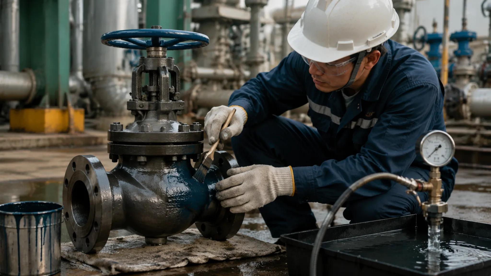
When there is 5 MPa fluid medium in the pipeline, the switching resistance of a 4-inch floating ball valve will break through 250 Nm. Master workers holding 50 cm ordinary wrenches simply cannot push it, and can only find a 1.2-meter long extended steel pipe to sleeve over the handle and press down hard. The torque issued by an ordinary worker’s bare hands is generally between 40 to 60 Nm, and 250 Nm of resistance is equivalent to requiring four or five strong men to exert force simultaneously.
Accompanied by a piercing metal friction sound, the PTFE sealing ring is bearing 8000 Newtons of unidirectional squeezing force. This unidirectional force causes the plastic material to undergo a permanent deformation of 0.2 to 0.5 mm. For a trunnion ball valve of the same size and pressure, the resistance is only 85 Nm, and one can easily rotate it 90 degrees by holding a 40 cm handle with one hand.
Inside the trunnion ball valve, there are two 35 mm thick stainless steel large shafts, fixing the ball body firmly in the exact center. No matter how fast the water flows in the pipeline, the ball body remains motionless. The floating ball valve is exactly the opposite, the water flow will push the ball body forward, pressing it deadly on the downstream sealing ring.
The downstream sealing ring of the floating ball valve gets hit every day, measured with a caliper, the thickness was worn away by 1.2 mm. The trunnion ball valve relies on the spring at the back of the seal seat to push toward the middle, wear on both sides is less than 0.1 mm, and the force is very even.
| Wear performance | Vernier caliper reading | Contact surface pressure situation | Leakage test after one year |
|---|---|---|---|
| Floating ball valve | Thinning more than 1.2 mm | Extremely uneven, exceeding material limit | Hovering at the edge of Grade C leakage |
| Trunnion ball valve | Almost no damage, less than 0.1 mm | Spring maintains 4 MPa constant pressure | Maintains Grade A standard of 0 bubbles |
After the floating ball valve is worn off-center, a 0.05 mm gap will flash out, and high-pressure gas carrying silt is like a knife cutting outward along the gap. The trunnion ball valve is equipped with 12 to 24 special alloy springs at the back, as long as the wear does not exceed 3 mm, the 150 Newton thrust of each spring can still plug the gap tight.
To repair a 4-inch floating ball valve, a worker must unscrew 8 large nuts and split the 25 kg iron lump into two halves, the entire pipeline must stop work for 2 hours. Changing to a 10-inch trunnion ball valve, the worker does not need to disassemble the pipeline joints, opening the top cover and spending 45 minutes can lift out the internal parts for replacement.
Going to an oil pipeline construction site in the Xinjiang Gobi Desert, it is 45 degrees Celsius during the day and drops suddenly to minus 15 degrees Celsius at night. The thermal expansion and contraction amplitude of the PTFE material used for sealing is more than ten times larger than that of steel. After a toss of heat and cold, the plastic ring in the floating ball valve contracted by 0.8 mm, and 0.2 MPa crude oil starts to seep out along the narrowed gap.
Even if the plastic ring cold-contracts by 0.8 mm, the spring will instantly push forward the same distance, maintaining the 4 MPa squeezing force. Going to check the line at midnight in winter, no trace of oil gas volatilization leakage point can be measured with instruments.
Sometimes liquid natural gas is stored in the pipeline, once the temperature rises to 30 degrees Celsius, the liquid turns into gas, and the volume expands instantly. The inside of the valve body is in a sealed state, and the pressure will directly double, rushing to more than 2 times the design limit. The trunnion ball valve has an auxiliary pressure relief function, when the pressure exceeds the spring endurance by 33%, the excess gas will automatically push open the valve seat and flow back to the main pipeline.
The floating ball valve completely lacks one exhaust path, and the 25 MPa gas is all suffocated in the belly. The cast iron valve stem, under 8000 Newtons of outward thrust, may at any time shoot out like a cannonball and injure people. Long-distance main pipelines explicitly stipulate that floating ball valves are absolutely not allowed to be installed in places with gasification risks.
An 8-inch trunnion ball valve weighs up to 320 kg, with 85 parts of extremely high processing precision stuffed inside. A floating ball valve of the same thickness is only 110 kg, with only 12 simple basic components inside, appearing very shabby in comparison.
| Internal configuration list | 8-inch equipment total weight | Bearing support system | Accidental scratch emergency channel |
|---|---|---|---|
| Floating ball valve | 110 kg | None | No remedial port whatsoever |
| Trunnion ball valve | 320 kg | Two self-lubricating bearings support the ball body | High-pressure grease injection hole to fill gaps |
The extra 210 kg of iron in the trunnion ball valve was exchanged for a set of grease injection holes for emergency use. When the detector finds trace methane escaping, the worker carries a grease gun to inject 70 MPa sealing grease. In less than half a second, the grease fills the 0.02 mm scratch between the metal and plastic tightly.
The floating ball valve’s smooth shell has no grease injection hole, and can only stare blankly when encountering a 1 mm pinhole scratch. The emergency repair team can only cut off both ends of the pipeline and vent all the gas in the pipeline before replacing the valve. The loss caused by 4 hours of gas stoppage easily exceeds 800,000, and this money can buy dozens of trunnion ball valves.
In a chemical plant, there are 260 degrees Celsius high-temperature steam pipelines, ordinary plastics would have long softened into a pile of mud at this temperature. It must be replaced with the extremely high-hardness special polymer material PEEK. Facing the rock-hard new material, the floating ball valve simply cannot squeeze it, and forced installation will leak 500 ml of gas per minute.
The trunnion ball valve, relying on the 24 disc springs inside, can squeeze out 6000 Newtons of brute force. No matter how hard the PEEK material is, it is still pressed flat against the ball surface. The outside of the ball body will also be sprayed with a 0.15 mm thick tungsten carbide layer, looking like a mirror under a microscope. Scoured by 12 MPa crude oil with coarse sand for half a year, the ball surface still has no damage of 0.01 mm.
Long-distance pipelines need to regularly send a cleaner in to scrape off scale. Inside the 12-inch trunnion ball valve is a complete 303 mm large passage, and the 15 kg cleaning equipment slides through at a speed of 8 kilometers per hour. If hitting a floating ball valve with a shrunken-down design, the passage suddenly narrows to 250 mm, and the cleaner will hit the step hard and get stuck.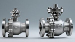
Factory Pressure Test
The worker fixes a 6-inch cast steel trunnion ball valve with three large hydraulic claws tightly clamping both ends. The water injection pump begins to roar, forcing tap water into the closed valve cavity. This equipment designed to withstand a maximum of 10 MPa pressure is about to welcome an excess punitive strike.
According to the operating specification requirements, the test water pressure is pushed all the way to 15 MPa, fully exceeding the rated upper limit by 1.5 times. The water temperature is strictly controlled below 38 degrees Celsius. Three quality inspectors holding flashlights walk around the 180 kg valve body to observe. Even if a water drop the size of a needle tip seeps out from the shell, this batch of castings with a total value of 400,000 must all be remelted and rebuilt.
For small-diameter equipment below 4 inches, the high-pressure state is maintained for 2 minutes. Changing to a 10-inch main trunk line ball valve, the pointer stays steadily on the 15 MPa scale for a full 5 minutes. Encountering a giant of 24 inches or more, the operator stares at the pressure gauge for a full 15 minutes, and the dial reading cannot slide down by 0.1 MPa.
The internal 15 MPa water pressure expands outward frantically, and the 12 high-strength bolts at the connection undergo tiny deformation. If the pre-tightening force is slightly short by 50 Newtons, a water column will immediately spray out from the flange gap. The trunnion ball valve, with a 60 mm thick integral forged outer shell, swallows the expansion force that could flip a car hard into its belly.
The shell held out, next, 0.55 MPa of dry compressed air is substituted and pumped into one side of the pipeline. The valve is closed tight, and the other side is connected with a transparent plastic hose, the mouth of the tube is soaked in a glass beaker filled with clean water. The quality inspector pulls out a stopwatch and starts to measure the low-pressure gas sealing condition.
Soft seal and metal hard seal have extremely distinct judgment boundaries in the beaker:
- PTFE soft material: Must achieve Grade A, 0 bubbles in water.
- Tungsten carbide hard coating: Relaxed to Grade D, allowing a tiny amount of bubbles to leak per minute.
- Special customized machined parts: Gas escape per second is locked within 0.3 ml.
- Extreme cold ultra-low temperature working condition: Measured at minus 196 degrees, using a helium detector to capture escaping molecules.
0.55 MPa of air pressure is very low, it cannot push that 15 kg ball body of the floating ball valve. Without fluid pressure, the fit between the ball surface and the seal seat is extremely loose, seven or eight large bubbles pop out in the beaker in one minute, and the equipment is scrapped on the spot. The 18 springs at the back of the trunnion ball valve still deadly push out 3000 Newtons of mechanical thrust under low pressure.
11 MPa high-pressure water is pumped into both sides of the pipeline simultaneously. The pointer on the pressure gauge soared from 0 to 11 MPa in just 8 seconds. The water flow frantically squeezes the O-ring rubber circle at the back of the valve seat, testing the real mechanical engagement force of cutting off the fluid.
For the trunnion ball valve, the quality inspector adds a double block and bleed test. Both ends of the pipeline are pressurized to 11 MPa simultaneously, sealing the high-pressure water on both sides of the ball body. The worker holding a wrench unscrews that small drainage hole at the bottom of the valve belly that is only 1/2 inch.
The 11 MPa high-pressure water on both sides is trying hard to drill into the dead corner of the valve cavity in the middle. If there is a slight lack of tightness in the valve seats on either side, the drainage hole below will spray a water column ten meters away like a fire hose. The worker stands less than half a meter away from the drainage hole staring at the pitch-black exit. For a full 5 minutes, not even a drop of water dripped from the drainage hole.
Floating ball valves naturally cannot block the water flow under two-way pressure, and simply cannot get on this double block test bench. When 11 MPa high-pressure water is pumped into both ends simultaneously, the ball body is instantly clamped in the middle and cannot move. Forcing open the middle cavity drainage hole, the 4000 Newton water thrust will crush the downstream seal seat, and the test bench will immediately be flooded with water.
Throughout the entire pressure-testing process, a torque wrench with an electronic reading records the extreme resistance of the metal twisting in real-time:
- No-load waterless opening: 8-inch trunnion ball valve only needs 35 Nm.
- Single side pressurized to 10 MPa: Switching resistance soared to 180 Nm.
- Both sides simultaneously filled with water and pressurized: Resistance fell back and stabilized at 95 Nm.
- Same specification floating ball valve under pressure: Torque meter went off the charts, breaking through 500 Nm.
A single inspection report is densely printed with more than 120 quantified factory indicators. From the furnace output time when 18% chromium element was added in the steelmaking furnace, to the 2 degrees Celsius fluctuation of ambient temperature during the water pressure test, it is black and white with a steel seal stamped on.
Pressure Limits
Medium and Low Pressure
A standard Class 150 level carbon steel ball valve is installed on a normal temperature water pipe, the pipeline pressure is rated at 285 psi, about 19.6 bar. Taking the 2-inch diameter for example, that fist-sized steel ball inside will be pushed by the water flow, bearing about 130 kg of thrust. The factory cooling water pipe pressure usually fluctuates around 8 to 10 bar.
When the diameter is changed to 4 inches, and the pipeline pressure is increased to 20 bar, the force pushing the ball rises to 1600 kg. That white PTFE gasket at the outlet is pressed deadly, the surface is squeezed with a 0.5 mm pit, just filling the micron-level fine lines left by the steel ball surface processing. According to the API 598 standard pressure test, when pressurized to 1.1 times the working pressure, not even a drop of water can leak.
Pure white PTFE will become soft and flat once the temperature exceeds 200°C. Chemical plants mix 15% glass fiber into the raw materials to make a reinforced version RTFE, forcibly pulling the compressive strength up to 25 MPa. A 3-inch pipe runs water day and night under 40 bar pressure, this reinforced gasket can hold on deadly, not to be crushed into plastic dross by the high-pressure water flow and fall into the deep part of the pipe network.
- Low-pressure gas pipelines under the residential building, gauge pressure controlled at 2 to 4 bar
- Central air-conditioning frozen water pipes in the basement of office buildings, pipe pressure 10 to 16 bar
- Air hoses pulled from the workshop air pump, conventional gauge pressure maintained at 7 to 10 bar
- Small thin water supply pipes next to large iron tanks, usually running water pressure not exceeding 5 bar
For a 2-inch low-pressure valve, opening it requires 40 N·m of force. The leverage ratio of that 20 cm long carbon steel handle originally equipped by the factory is just right, an adult male worker grabbing it single-handedly can easily turn the valve 90 degrees with 50 pounds of force.
When the pipe diameter is expanded to 8 inches, and the system parameters are adjusted to Class 300 level, the cross-sectional area under pressure is stretched to 320 square centimeters. The force pushing the ball breaks through the 16-ton mark like a runaway horse. The originally sturdy plastic ring is crushed flat, and the metal parts bite and friction deadly between each other, the resistance for the worker to turn the handle will go all the way through the 1200 N·m dangerous red line.
The API 6D life test machine in the lab simulates pressure switching day and night. The 2-inch diameter at 20 bar pressure opens and closes 10,000 times continuously, opened up to see that plastic gasket inside can still maintain 15% resilience. Changed to a 6-inch large pipe running continuously at 50 bar for 1500 times, the high temperature from parts dry-rubbing will burn long-strip scratches on the plastic surface.
- Working workers must find a one-meter long iron pipe to sleeve over the handle to gain leverage to turn it
- Putting the ear close to the downstream outlet can hear the hissing sound of the plastic gasket leaking gas
- Opening the metal filter at the end of the pipe during maintenance, it holds a handful of white dross inside
- When the test pressure pump reaches 50 bar, a string of water beads appears from the packing at the valve neck
Buying a 2-inch conventional model made of WCB cast steel only costs 150 US dollars. For the same size heavy-duty version with four sliding bearings installed, the manufacturer’s quote sheet says 600 US dollars. The conventional model removes 2 fixed bases and 8 sets of spring washers for pre-tightening, the savings are all real steel material usage and mechanical processing expenses.
The cooling tower standing in the open air of the chemical plant swallows and spits 15,000 gallons of circulating water per minute, the pipe pressure is nailed at 6 bar all year round. Hundreds of 100 mm thick control valves densely packed are all equipped with the conventional version. The ball body polished from 316 stainless steel will not rust when soaked in sodium hypochlorite disinfectant water, and the gasket rated to resist 12 bar actually only bore half of the thrust.
That bit of residual water trapped in the ball hole expands its volume by 1% for every 10°C increase in surrounding temperature. About 150 ml of dead water is stored in the 2-inch inner cavity. The summer sun directly baking the iron pipe from 20°C to 60°C, the water pressure in the belly of the iron lump pierces through 100 bar. That flexible plastic gasket at the front end will be forcibly pushed open a fine crack to squeeze out a few drops of expanded water for pressure relief.
- Using Devlon V special composite material to withstand the 100 bar instant water hammer impact
- Stuffing in a few rings of flexible graphite packing to deal with the API 607 standard fire burning test
- Connecting a small steel wire with a resistance of less than 10 ohms on the inner side to conduct static electricity into the ground soil
- Cutting a 45-degree bevel at the bottom of the valve stem to prevent it from being shot out like an iron cannonball by water pressure
High Pressure & Ultra-high Pressure
Once the pipeline pressure leaps over the 102 bar threshold, the steel ball originally pushed by the water flow completely fails to work. In Class 600 level natural gas long-distance pipelines, a 24-inch pipe must be installed with a solid stainless steel ball body weighing up to 3 tons. The thrust generated by the fluid is no longer several hundred kilograms, but instantly surges to 450 tons.
The factory drills deep holes in the top and bottom of the ball, forcing in two thick high-strength forged steel rotating shafts. The steel ball is deadly clamped in the upper and lower metal bases, unable to move even one millimeter. The 450 tons of violent thrust is fully taken up by these two rotating shafts and the attached 8 sliding bearings.
24 finger-thick Inconel springs are evenly distributed on both sides of the outlet. They push a nylon sealing ring mixed with carbon macromolecules to actively press forward against that metal ball that will not move at all. When the pressure in the pipeline is added to 150 bar, the nylon ring only bears 600 Newtons of pre-tightening force from the spring, plus a small section of local water pressure. The metal parts bear 99% of the physical destructive force, and the soft sealing ring is only responsible for doing its duty of plugging leaks.
Even if 250 bar high-pressure crude oil is running in the pipe, rotating that 3-ton ball body only needs to overcome the tiny friction in the bearings. A hydraulic actuator with a conventional configuration outputs 3500 N·m of force, and it can smoothly cut off the violent flood of a 36-inch main line in 12 seconds.
The pressure gauge pointer climbed to the Class 1500 scale line, corresponding to the 255 bar mark. Ordinary nylon material lasts less than three days in a 200°C mixed hydrocarbon fluid before blistering and bulging. The machining workshop switched to PEEK special polymer material. This yellowed hard plastic can withstand 100 MPa of tensile strength, even if soaked in 260°C high-temperature oil stain for half a year, pulled out and measured with a caliper, the deformation size absolutely does not exceed 0.05 mm.
Facing various severe physical working conditions, parts material selection and process dimensions have clear numerical requirements.
Deep-sea water injection pipe network (Class 2500)
- Operating gauge pressure stably at the 420 bar peak for a long time
- Internal cavity wall thickness increased to 125 mm heavy-duty specification
- Equipped with Inconel 718 material bellows for anti-corrosion
- Water pressure test for 15 minutes, pressure drop less than 0.1 bar
Natural gas purification plant trunk line (Class 900)
- Hydrogen sulfide gas flow rate in the pipe 20 meters/second
- Using double-sided fitting double piston effect valve seat structure
- Blocking the reverse surge of 153 bar mixed gas
- Cavity reserves a three-quarter inch safety pressure relief hole
Flipping through the heavy-duty pipeline procurement specification book, the correspondence parameters of component sizes and pressure levels are laid out clearly.
| ASME standard level | Conventional gauge pressure in pipe | Adapted diameter extreme | Seal base main material |
|---|---|---|---|
| Class 600 | 102 bar | 60 inches | Reinforced nylon (Nylon) |
| Class 900 | 153 bar | 48 inches | Polyetheretherketone (PEEK) |
| Class 1500 | 255 bar | 36 inches | Devlon composite hard plastic |
| Class 2500 | 425 bar | 24 inches | Tungsten carbide metal spray coating |
When the pipe network pressure reaches the 425 bar peak, all kinds of plastic gaskets will be torn like butter. The lathe master must spray a 0.3 mm thick tungsten carbide powder on the surface of the stainless steel ball. After throwing it into a 1000°C high-temperature furnace for sintering, the surface hardness climbs all the way to HRC 72. The metal surfaces bite deadly hard against each other, even if the pipe is mixed with 2 mm iron rust sand, the valve can smoothly cut through it like a guillotine when closing.
The third-party inspector holds a strong flashlight and shines it into the pitch-black pipe to do API 6D factory acceptance. 600 bar high-pressure nitrogen is pumped into the pipe and suffocated, let stand for 5 minutes to test air tightness. The probe of the testing instrument rotates at the outlet, the micro-leakage rate displayed on the screen is limited to within 10 cubic centimeters per minute. The valve stem gap part exposed on the outside must be smeared with soapy water, and not even a single visible 1 mm small bubble is allowed to pop out.
The heavy crawler crane of the Pipeline Bureau slowly places this 8-ton iron lump into a 3-meter deep yellow earth ditch. The welder holds an argon arc welding gun crawling all over the 36-inch thick iron pipe mouth, burning 12 kg of solid welding wire before finally filling the interface gap completely. In the decades buried underground, it must independently cope with the frost soil contraction and cracking at minus 30°C every winter, and withstand the pulse vibration of 100 bar natural gas in the pipe day and night.
Selection Guide
Size & Pressure Boundaries
Running 2.0 MPa room temperature natural gas inside, close a ball body without bearing support. There is approximately 1.5 tons of weight deadly pressing on a stainless steel ball with a diameter of more than ten centimeters.
That 1.5 tons of force all falls on the PTFE sealing ring behind the ball body. This plastic material can withstand a pressure of 14 to 25 MPa at room temperature. The 2.0 MPa thrust causes the plastic ring to produce a micro-deformation of a few millimeters.
When the pipe network pressure crosses the ASME Class 300 (about 5.1 MPa) boundary line, the gas thrust in the DN100 pipeline soared to nearly 4 tons. The heavy pressure presses the metal ball hard against the surface of the sealing ring. Ordinary materials cannot withstand the continuous heavy pressure and are quickly crushed flat or even overflow the groove.
- PTFE room temperature limit: 14 to 25 MPa
- Parapolyphenylene temperature resistance range: -29℃ to 250℃
- Class 300 design pressure: 5.1 MPa
- DN100 cross-section thrust: about 4 tons
The flow rate in the pipe is maintained between 10 meters/second to 20 meters/second. High-speed fluid mixed with fine sand and gravel instantly cuts the deformed plastic ring like a file. The operator goes to twist the handle, the friction coefficient soared from 0.04 to above 0.2. An extended wrench as long as 1.5 meters cannot move it. Forcing it with a high-power motor, in less than 10 switching cycles, the sealing ring is completely torn and scrapped.
Once the pipe diameter and pressure are enlarged, a different mechanical structure must be changed. Expanding the diameter to DN300 and pulling the pressure up to Class 900 (about 15.3 MPa), the thrust reaches a shocking 108 tons. Relying on the downstream plastic ring to block the 108-ton impact is no different from hitting a rock with an egg.
A thick solid metal support shaft is welded to each of the upper and lower ends of the ball body. The two shafts are tightly inserted into the metal bearings of the valve body. 108 tons of medium thrust is all transmitted through the bearings to the cast steel shell with a thickness reaching several centimeters. The ball body itself is as steady as Mount Tai, spinning in place, and will not shift downstream even by 0.1 mm.
- Fixed bearing conventional material: F316 or 17-4PH
- Valve seat spring pre-tightening force: 0.2 to 0.5 MPa
- Class 1500 working pressure: 26.0 MPa
- Thrust transfer ratio: nearly 100%
Behind the metal rings on both sides, 12 to 24 spring components are evenly distributed. The springs provide tens of kilograms of initial fitting force. The valve seat carrying the non-metallic ring is actively pushed toward the ball body in the middle, completing the initial blockage. Each spring must undergo at least 5000 compression fatigue tests before leaving the factory to ensure that the force lasts without weakening.
When the pressure in the pipeline climbs to ASME Class 1500 (about 26 MPa), the high pressure of the fluid itself will drill into the tiny cavities behind the valve seat. The piston effect works, and the hydraulic force pushing the valve seat against the ball body doubles accordingly. The metal-to-metal rigid frame support forcibly seals the extremely high pressure of 26 MPa in the few cubic centimeters of gap.
Drastic fluctuations in ambient temperature severely interfere with the physical extremes of non-metallic materials. For long-distance pipelines in the northern winter, the temperature of the metal pipe wall exposed outdoors drops to minus 40℃. Under extreme cold conditions, conventional materials become brittle and completely lose elasticity. Switching to PCTFE or nylon materials can resist the severe cold and maintain the sealing state.
- PCTFE extreme cold applicable lower limit: -196℃
- PEEK high temperature operation upper limit: about 260℃
- Hard alloy surface hardness: HRC 40 to 50
- Metal seal leakage standard: ANSI FCI 70-2 Class V
Industrial steam pipelines start blowing sweep operations, the internal temperature soared to above 200℃, and PEEK material takes over. The engineering world widely uses P-T curves to calibrate boundaries. The horizontal axis marks temperature, and the vertical axis marks pressure. For every 10℃ the temperature rises, the pressure data the material can withstand will drop according to a specific ratio. Reaching the critical point of 250℃, the conventional PTFE material is completely softened into a mud shape.
Encountering a 500℃ high-temperature oil refining catalytic cracking pipeline, all plastic rings turn to ash. The sealing surfaces are all replaced with pure metal components surfacing-welded with Stellite hard alloy. The surface hardness reaches above HRC 45. Tens of MPa of pressure relies on the precise grinding of surface roughness Ra 0.1 to squeeze together hard to block the fluid.
A small DN50 pipe running in a Class 600 (10.2 MPa) pipe network, a ball body without bearings can barely hold on for a few months. Changed to a DN150 thick pipe running under a Class 150 (2.0 MPa) low pressure, the procurement list has already filled in that model with bearings. The square-level amplification of thrust brought by the doubling of pipe diameter is evident.
Operation Torque Comparison
Take a most ordinary DN50 diameter ball valve for testing, running 1.0 MPa industrial water in the pipe. A stainless steel handle about 25 cm long, an adult can easily push it open by applying about 15 kg of pulling force with one hand. The starting torque displayed on the torque meter screen is about 35 N·m.
The ball body without bearing support relies entirely on the water pressure in the pipe to push backward, pressing deadly on the PTFE sealing ring. The friction value climbs synchronously with the water pressure scale. Pulling the pressure in the pipe up to ASME Class 300 (about 5.1 MPa), the torque to push open the same DN50 valve soared to 120 N·m. The original 25 cm handle cannot be moved, and the worker must switch to an extended sleeve as long as 80 cm.
Large-diameter pipelines amplified the force value by more than ten times. The cross-sectional area of DN150 diameter soared, even for low-pressure natural gas at room temperature 2.0 MPa, the thrust friction resistance produced by a ball body without bearings also approached 800 N·m. Pure reliance on manpower plus leverage completely fails. The worker must install a worm gear manual gearbox with a reduction ratio of 50:1 at the top of the valve stem.
The structure with a solid fixed bearing changed the mechanical force point. The metal bearing bore several tons of natural gas thrust, and the rigid friction between the ball body and the downstream sealing ring was stripped away. Testing the physical data of DN150 diameter at 2.0 MPa pressure, the starting torque of the structure with bearing support fell back to around 400 N·m.
The 800 N·m resistance requires the factory to configure a large double-acting cylinder with a cylinder bore of 200 mm. The shell length exceeds 85 cm, and the single cylinder weight approaches 60 kg. For the cylinder assigned to the bearing valve with 400 N·m, the cylinder bore only needs to be reduced to 140 mm.
The air pressure is maintained at the standard instrument air of 0.5 MPa, pushing open that 200 mm bore cylinder consumes about 15 liters of compressed air each time. The air consumption of the 140 mm bore cylinder is sharply reduced to less than 6 liters. Hundreds of devices opening and closing dozens of times a day, the difference in numbers on the electricity bill is clearly visible.
The motor power of the electric actuator fluctuates up and down with the force value. To cope with the huge friction resistance of the ball body without bearings, the explosion-proof motor power equipped is usually 1.5 kW or more. The cable cross-section should use thick copper wire of 3 cores and 4 square millimeters. Equipment with bearing structure has small friction, and a 0.55 kW micro motor can drive the entire mechanical operation.
The pipe network temperature rises to 150℃, conventional PTFE material retreats, and PEEK polyetheretherketone material with higher hardness is replaced. The sliding friction coefficient between PEEK and the stainless steel ball is around 0.12, three times higher than PTFE’s 0.04. The original estimated torque value must be forcibly multiplied by a safety factor of 1.5 in the table.
Crude oil with tiny impurities remains static in the pipeline for a long time, and the viscous liquid dries and clumps at the edge of the sealing surface. The equipment is parked outdoors for more than three months without rotating, the resistance of the first power-on opening is extremely high. The instant physical peak captured by the torque meter is at least 30% higher than the sliding torque during daily continuous operation.
The selection of gearboxes and motors is derived by checking tables against physical force limits. Pipe diameter, pressure, and sealing ring friction coefficient—these three numbers multiplied define the reaction speed of mechanical components at the moment the control room presses the switch. Once the torque calculation is wrong, the explosion-proof motor on site will only emit a dull overload hum.
| Test diameter and pressure | Torque of ball without bearing (N·m) | Torque of ball with bearing support (N·m) | Recommended cylinder bore for matching |
|---|---|---|---|
| DN50 / 2.0 MPa | 35 | 25 | 80 mm |
| DN50 / 5.1 MPa | 120 | 65 | 100 mm |
| DN150 / 2.0 MPa | 800 | 400 | 200 mm |
| DN150 / 10.2 MPa | Over 3000 (facing jamming) | 1200 | 300 mm |
| DN300 / 15.3 MPa | Unable to operate | 3500 | 500 mm |
- Sealing surface contact specific pressure: Spring pre-tightening force is between 0.2 to 0.5 MPa, constituting an initial running resistance of dozens of Newtons.
- Valve stem packing friction: V-type graphite rings are fastened on the outside of a 30 mm diameter metal rod, contributing about 15% of the overall wear reading.
- Fluid dynamic viscosity: Heavy oil has a dynamic viscosity thousands of times larger than clear water, adding a huge medium shear torque between gaps of a few millimeters.
- Temperature thermal expansion and contraction: At 200℃ high temperature, the stainless steel ball thermally expands 0.3 mm, hard-squeezing the polymer valve seats on both sides and pulling up the reading.
API 6D & DBB
Running 12.0 MPa high-pressure gas in the pipe network, maintenance workers need to cut an opening of dozens of centimeters in the middle of two pipe sections. The high pressure at both ends is blocked deadly by steel valves. The worker unscrews that 1/2-inch small sewage valve in the middle of the valve body, and accompanied by a piercing hissing sound, the residual gas accumulated inside the valve cavity is vented.
The pointer on the pressure gauge drops to the 0 MPa scale. Touching the fully open sewage small valve with a finger, the rapid expansion of gas absorbing heat makes the metal surface covered with frost, and the temperature drops below minus 15℃. At this time, the 12.0 MPa terrifying pressure is still maintained in the pipelines on the left and right ends respectively.
The ball body without bearing support, under 12.0 MPa thrust, will press deadly on that downstream PTFE sealing ring. The upstream sealing ring at this time is completely in a suspended state, and the cavity of dozens of cubic centimeters in the middle is filled with high-pressure natural gas. Going to unscrew the small sewage valve to reduce pressure, the metal ball losing the support force inside the valve cavity will produce a micro-rebound of 0.5 mm.
On the pressure test bench in the factory workshop, the structure with bearings demonstrated a completely different physical engagement. Each of the left and right sides is installed with a set of movable metal valve seats containing 24 cylindrical spiral springs. The springs provide a thrust of about 0.3 MPa, actively pushing the metal seat with a rubber ring toward that stainless steel ball weighing 80 kg in the exact center.
The piston effect converts all 12.0 MPa of pressure into thrust, pushing the valve seats on both sides to tightly embrace the ball body. Venting the cavity in the middle, the natural gas on both sides not only will not backflow, but because of the loss of resistance inside, the external hydraulic thrust of 12.0 MPa on both sides presses the valve seats even tighter.
The API 6D document stipulates the industrial code for this physical action: DBB (Double Block and Bleed). On the test bench before leaving the factory, the quality inspector pumps clean water of 1.5 times the design pressure into both sides of the valve simultaneously. A device rated Class 600 must withstand water pressure as high as 15.3 MPa in both side pipelines. During the 5-minute pressure-holding test period, not even a drop of water is allowed to leak from the small discharge hole opened in the middle.
A section of DN200 pipeline filled with aviation kerosene, the metal skin temperature rises 25℃ at noon. The kerosene of several hundred milliliters sealed between the two rings of valve seats undergoes thermal expansion. Liquid possesses almost no compressibility, and several hundred milliliters of kerosene instantly prop the pressure inside the valve cavity up to above 35.0 MPa.
The API 6D specification mandates the access of a single piston effect (SPE) pressure relief design. The two rings of movable valve seats push inward when bearing pressure on the back, and retreat outward when bearing pressure on the front. When the kerosene pressure in the valve cavity is higher than the outside pipeline pressure by about 1.33 times, the 35.0 MPa internal expansion force forcibly overcomes the dozens of spring resistances at the back. The valve seat is forced to retreat by about 2 mm, a few milliliters of high-pressure kerosene leak into the pipeline, and the pressure in the cavity falls back to within the safety red line.
- Water pressure shell test: Pump in 1.5 times the rated pressure, 10.2 MPa pipeline pressurized to 15.3 MPa, lasting for 15 minutes.
- Gas seat seal test: Using 0.6 MPa low-pressure nitrogen to test initial fit, the bubbling rate in the water tank is strictly controlled at ISO 5208 Grade A.
- Torque recording requirements: Continuously switch 3 times under full pressure difference, the electronic torque meter records the Newton-meter data of each push and pull and issues a chart.
- In-cavity pressure relief setting: When temperature rise leads to internal overpressure of 33%, the sealing spring undergoes micro-deformation to complete liquid discharge and pressure reduction.
A fire breaks out in a petrochemical plant area, the temperature outside the pipeline soared to 760℃ in just a few minutes. Non-metallic rubber and PTFE sealing rings completely soften at 200℃ and turn into charcoal at 300℃. The originally tight non-metallic barrier layer disappears, and the high-pressure flammable liquid is about to burst through the defense line.
After the outer ring polymer is burned out, the fluid thrust inside the pipeline pushes that metal movable valve seat, which has lost its rubber gasket, heavily toward the ball body which is also pure metal. Two pieces of stainless steel parts with surface roughness reaching Ra 0.1 micron level have a rigid collision. Relying on dozens of tons of thrust to squeeze together hard, under 30 minutes of 760℃ fire roasting, the leakage amount is limited to within 400 ml per minute.
High-speed flowing natural gas frictions with the polymer plastic sealing ring, generating static charges as high as thousands of volts. A metal ball isolated and suspended in the middle turns into a huge capacitor. The worker must drill a deep hole at the bottom of the 30 mm diameter valve stem and plug in a small conductive steel ball with a diameter of 5 mm, then press a micro spring on the outside.

")