
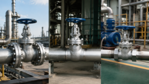
The choice of valve end connections in industrial pipelines directly affects sealing reliability, maintenance access, installation cost, and long-term safety.
This article explains how to select flanged, buttweld, threaded, and clamp-type valve end connections for chemical plants, refineries, steam systems, hydrogen service, utility lines, and sanitary processes. The selection logic is based on commonly used piping and valve standards such as ASME B16.5 for pipe flanges, ASME B16.34 for valves, ASME B16.25 for buttwelding ends, ASME B31.3 for process piping, ASME PCC-1 for bolted flange joint assembly, ASME B1.20.1 for NPT threads, ISO 15848 for fugitive-emission testing, and project-specific engineering requirements.
| Connection Type | Best Use | Main Advantage | Main Limitation |
|---|---|---|---|
| Flanged | General process lines, utility systems, maintenance points | Easy disassembly and replacement | Creates gasket and bolt-preload leakage paths |
| Buttweld | High-pressure, high-temperature, hydrogen, toxic, flammable, buried, or difficult-access service | No gasketed end-joint leakage path | Valve removal usually requires cutting and rewelding |
| Threaded / NPT | Small-bore auxiliary and low-risk service | Compact and low cost | Limited reuse reliability; sensitive to sealant, vibration, temperature, and installation quality |
| Clamp Quick-Connect | Sanitary, CIP/SIP, food, beverage, and pharmaceutical systems | Very fast disassembly and cleaning | Pressure and temperature limits depend strongly on clamp design and gasket material |
The correct valve end connection is not simply the cheapest option. It is the connection that matches design pressure, design temperature, leakage consequence, maintenance frequency, installation constraints, and applicable code requirements.
Flanged Connections
Raised Face vs Ring-Type Joint
RF raised face and RTJ ring-type joint are common sealing face options for industrial valve flanges. The correct selection depends on pressure class, temperature, gasket type, leakage consequence, bolting control, and owner specifications.
| Item | RF Raised Face | RTJ Ring-Type Joint |
|---|---|---|
| Common pressure class range | Frequently used from Class 150 to Class 600; may also be used at higher classes where permitted by specification | Frequently used from Class 600 upward in severe or high-pressure service |
| Sealing method | Soft, semi-metallic, or metallic gasket compression | Metal ring gasket seating in machined grooves |
| Typical application | General refinery, chemical, water, steam, and utility service | High-pressure steam, hydrogen, hydrocarbon, and severe-service applications |
| Maintenance | Gasket replacement is relatively simple | Requires accurate groove condition, correct ring gasket, and controlled bolt loading |
- RF flanges rely on gasket compression to fill surface irregularities and maintain sealing stress.
- RTJ flanges use a metallic ring gasket seated in a machined groove and are often selected where high pressure or severe leakage consequence makes gasketed RF sealing less desirable.
- ASME PCC-1 provides guidelines for pressure-boundary bolted flange joint assembly, including joint preparation, alignment, tightening practices, and gasket-stress control[1].
- ISO 15848 fugitive-emission testing should not be used to qualify leakage at valve end connections, because ISO 15848-2 applies to external leakage from valve stems or shafts and body joints, while end-connection joints are excluded[2].
In one high-pressure steam valve review, an RF flange design showed gasket seating sensitivity during repeated assembly checks. Because the service involved elevated temperature, thermal cycling, and low tolerance for leakage, the engineering team evaluated RTJ as an alternative. The RTJ option reduced dependence on soft gasket recovery and provided a more robust sealing arrangement for the service.
This type of result should be described as a project case example, not as an ISO 15848-2 Class A result. ISO 15848-2 is a fugitive-emission production acceptance test for valves and does not cover flange end-connection leakage.
For Class 900 and above, or for services above about 350°C where leakage consequences are high, RTJ or buttweld ends should be evaluated instead of automatically selecting RF flanges.
RTJ joints usually require more precise machining, correct ring-gasket selection, and better-controlled bolting practices than ordinary RF joints. Their initial cost is higher, but they can reduce leakage risk in severe services when correctly specified and assembled.
For Class 600 and below in general process service, an RF flanged valve can provide a practical balance between cost, maintainability, and sealing performance. For high-pressure steam, hydrogen-rich media, or severe cyclic service, RTJ or buttweld ends should be evaluated during the valve specification stage.
Further reading: CARILO API 6D Ball Valve Flange Specifications.
ASME Pressure Classes from Class 150 to Class 2500
ASME pressure classes from Class 150 to Class 2500 cover most industrial flange and valve applications. The key rule is that pressure class must be checked at the actual design temperature and material group, not only at room temperature.
| Pressure Class | Typical Use | Approximate Rating at 38°C for Common Carbon Steel Group 1.1 |
|---|---|---|
| Class 150 | Low-pressure utility and general service | About 1.96 MPa(g) |
| Class 300 | Medium-pressure process service | About 5.11 MPa(g) |
| Class 600 | Refinery and chemical process service | About 10.2 MPa(g) |
| Class 900 | High-pressure process and steam service | About 15.3 MPa(g) |
| Class 1500 | Severe high-pressure service | About 25.5 MPa(g) |
| Class 2500 | Very high-pressure severe service | About 42.5 MPa(g) |
- ASME B16.5 defines pressure-temperature ratings for pipe flanges and flanged fittings[3].
- ASME B16.34 covers pressure-temperature ratings and other requirements for flanged, threaded, welding-end, and wafer-type valves[4].
- Pressure-temperature ratings vary by material group and edition. Final selection must always be verified against the applicable standard edition and project design code.
Material derating at elevated temperature is significant. For example, a Class 300 carbon steel flange rated around 5.1 MPa(g) at 38°C may have a lower allowable pressure at 260°C, 320°C, or 400°C. The exact value depends on the ASME edition, material group, and valve or flange standard used.
On a chemical plant line with a design pressure of 2.5 MPa(g) and a design temperature around 260°C, Class 150 may appear acceptable if only ambient ratings are considered. However, after checking the pressure-temperature table at the actual design temperature and material group, Class 300 may be required to maintain adequate margin.
- Confirm the design pressure.
- Confirm the design temperature.
- Confirm the valve body and flange material group.
- Check the applicable ASME B16.5 or ASME B16.34 pressure-temperature table.
- Select the lowest class that safely covers both pressure and temperature, including project margin.
- Record the verification temperature and rating in the valve datasheet.
A common specification mistake is selecting a pressure class based only on ambient-temperature pressure ratings. This is especially risky for steam, thermal oil, hydrogen, and high-temperature hydrocarbon systems. Adding a “pressure-temperature rating checked at design temperature” field to the valve datasheet helps prevent this error.
Select from the CARILO Ball Valve Pressure Class Range covering 150 to 2500LB.
Further reading: CARILO Ball Valve Pressure Class Coverage.
Gasket Matching for Flanged Valves
Flange gasket selection is directly tied to flange face type, pressure class, temperature, media, bolt load, surface finish, and flange rigidity. The gasket must be selected as part of the flange joint system, not as an isolated consumable item.
| Gasket Type | Typical Flange Face | Typical Class Range | Typical Temperature Suitability |
|---|---|---|---|
| Compressed fiber / non-asbestos gasket | RF | Often Class 150 and low-risk service | Depends on material grade; commonly limited in high-temperature steam |
| Spiral-wound gasket with graphite filler | RF | Commonly Class 300 to Class 900 | Often used for steam and cyclic temperature service when compatible with the flange and media |
| Metal ring gasket | RTJ | Commonly Class 600 to Class 2500 | Suitable for many severe high-pressure and high-temperature services |
- Compressed fiber gaskets are economical but must not be used beyond their certified pressure-temperature and chemical limits.
- Spiral-wound gaskets with stainless steel winding and flexible graphite filler are commonly selected for RF flanges in steam and thermal cycling service.
- Metal ring gaskets are used with RTJ flanges and require groove condition, gasket hardness, and bolting practice to be controlled.
- ASME PCC-1 should be used as a reference for bolted flange joint assembly practices and gasket-stress control[1].
On a chemical plant Class 300 steam line at about 230°C, a compressed fiber gasket showed leakage after several months of service. It was replaced with a spiral-wound gasket using stainless steel winding and flexible graphite filler, which was more suitable for steam and cyclic temperature service. After replacement, the joint passed the project leak checks.
This result should not be described as an “ASME Class A” leakage result unless a specific recognized leakage or fugitive-emission standard is tested and cited. For valve fugitive emissions, ISO 15848 applies to stem, shaft, and body-joint leakage, not to end-connection joints.
Gasket selection is not about choosing the thickest gasket. It is about matching flange face, gasket stress, recovery, temperature, media compatibility, and assembly method.
For RF faces, the CARILO Gasket Selection Guide can be used to coordinate gasket type with valve pressure class, flange face, temperature, and service media.
Further reading: CARILO Gasket Selection Recommendations.
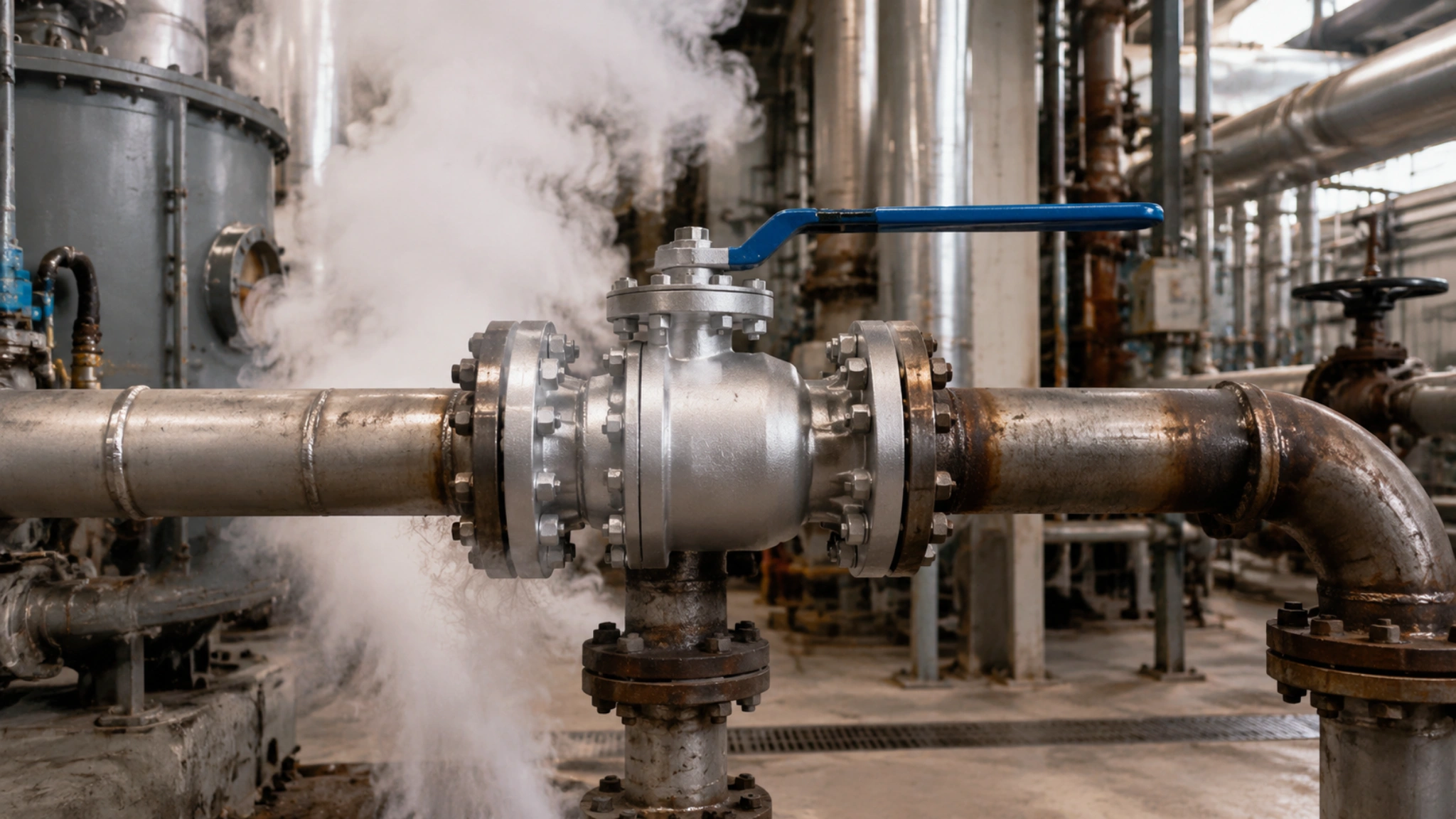
Buttweld Connections
When Buttweld Ends Should Be Evaluated
Buttweld valve ends are often specified or strongly preferred in severe services where a gasketed flange joint creates unacceptable leakage, fire, maintenance, or reliability risk.
Buttweld ends are commonly evaluated for high-pressure and high-temperature service, hydrogen service, toxic or highly flammable media, buried or subsea pipelines, and locations where maintenance access is limited.
- High-pressure or high-temperature service where flange leakage consequences are severe.
- Hydrogen-rich, toxic, flammable, or hazardous media.
- Buried, subsea, or difficult-access systems.
- Systems where flange maintenance is difficult or leakage is not acceptable.
- Project specifications that restrict gasketed joints in critical service.
Buttweld joints remove the gasketed valve end-joint leakage path. When designed, welded, heat-treated, and inspected correctly, the weld joint can provide structural integrity comparable to the connected piping system.
ASME B16.25 covers the preparation of buttwelding ends for piping components, including welding bevels, internal and external shaping of heavy-wall components, and preparation of internal ends with dimensions and tolerances[5].
- Check whether the medium is hazardous, flammable, toxic, hydrogen-rich, or environmentally sensitive.
- Check whether the service involves high pressure, high temperature, severe cyclic loading, or difficult maintenance access.
- Check whether the valve requires frequent removal for cleaning or repair.
- If leakage consequence is more important than easy removal, evaluate buttweld ends.
- Confirm weld-end preparation, material compatibility, NDT, PWHT, and field installation requirements before procurement.
The disadvantage of buttweld ends is that valve removal usually requires cutting, rewelding, inspection, and sometimes post-weld heat treatment. Therefore, buttweld valves are less convenient on lines requiring frequent maintenance. However, for severe high-pressure, high-temperature, hydrogen, toxic, or buried service, buttweld ends can be the more reliable lifecycle option.
The CARILO API 6D Buttweld Ball Valve can be specified with weld ends prepared according to project requirements and applicable standards.
Further reading: CARILO Buttweld Ball Valve Specifications.
Pipe Matching for Buttweld Valve Ends
Welding a buttweld valve end to a pipeline requires strict checking of material grade, wall thickness, outside diameter, weld-end preparation, chemical compatibility, impact toughness, and any post-weld heat treatment requirement.
| Matching Item | What to Check | Risk if Ignored |
|---|---|---|
| Material | Valve body and pipe material grade | Dissimilar-metal cracking, corrosion, or metallurgical incompatibility |
| Wall thickness | Pipe schedule and valve weld-end thickness | Stress concentration at weld transition |
| Bevel preparation | Bevel angle, land, root gap, internal transition | Poor penetration, rework, or weld defects |
| Impact toughness | Low-temperature or service-specific impact requirement | Brittle fracture risk |
| PWHT requirement | Material, thickness, service, and code requirement | Residual stress, hardness, or cracking risk |
Dissimilar-metal welding, such as stainless steel valve bodies to carbon steel piping, must follow the project welding procedure specification. Filler metal selection depends on base metals, temperature, corrosion environment, strength requirement, and owner metallurgy rules. Nickel-based filler metals may be required in some critical services, but they should not be described as universally mandatory for every stainless-to-carbon-steel transition.
Wall-thickness matching is equally important. If the valve weld end is thicker than the connected pipe, the transition must meet applicable code and project requirements so that stress concentration and weld geometry problems are avoided. ASME B16.25 is the normal reference standard for buttwelding-end preparation of piping components[5].
Impact toughness should be checked when low-temperature service, sour service, cryogenic service, or project specifications require it. The stricter requirement between valve specification, pipe specification, and owner standard should be applied.
Pipe matching is not simply “the same nominal size will work.” It requires simultaneous consideration of material, wall thickness, weld-end preparation, thermal expansion, high-temperature strength, corrosion allowance, and inspection requirements.
The CARILO Forged Ball Valve Weld End Matching can be specified to coordinate valve weld ends with pipe schedule, material, and project welding requirements.
Further reading: CARILO Forged Ball Valve Material Standards.
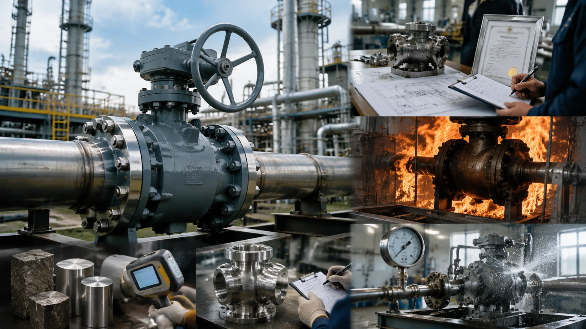
Weld Inspection Requirements
Buttweld joints require inspection to confirm weld integrity. The required inspection method and coverage depend on the piping code, fluid service category, joint type, material, wall thickness, design conditions, severe cyclic service, owner requirements, and project specification.
| Inspection Method | Main Purpose | Typical Use |
|---|---|---|
| VT | Surface condition, profile, alignment, and visible defects | Normally applied to all welds |
| RT / DR | Volumetric examination for internal defects | Critical pressure welds or project-specified welds |
| UT / PAUT | Volumetric examination without radiation | Thick-wall, restricted-access, or productivity-sensitive projects |
| MT / PT | Surface or near-surface crack detection | Final surface examination where required |
| Hardness Testing | Control of hydrogen cracking or sour-service risk | Hydrogen, sour, high-strength, or project-specified service |
For ASME B31.3 piping, 100% radiography is not automatically required simply because a line is Class 600 or above. ASME B31.3 uses fluid service categories and other design factors to determine examination and testing requirements. More stringent requirements may apply for Category M, high-pressure fluid service, severe cyclic service, owner-specified critical service, or project-specific quality plans[6].
For critical service, the valve datasheet or project specification should explicitly state:
- Required NDT methods.
- Required examination percentage.
- Acceptance criteria.
- PWHT requirements if applicable.
- Hardness testing limits if applicable.
- Hydrostatic, pneumatic, sensitive leak, or alternative leak-test requirements.
PAUT is increasingly used as an alternative to RT where permitted by the project specification and code basis. It can reduce radiation-control issues and improve productivity, but acceptance criteria, calibration, personnel qualification, and reporting requirements must be clearly defined.
Hardness testing may be required for hydrogen, sour, high-strength, or owner-specified services. The allowable hardness value should come from the applicable project specification, material standard, NACE/ISO sour-service requirement where applicable, or welding procedure qualification. It should not be presented as a universal single value for all hydrogen services.
For buttweld valves, the CARILO Weld Inspection Services can be aligned with API 6D, ASME B31.3, ASME B16.25, and project-specific NDT requirements.
Further reading: CARILO Weld Inspection Consulting.
Other Valve End Connection Types
NPT Threaded Connection Limitations
NPT tapered pipe threads are commonly used for small-bore auxiliary service, instrument connections, vents, drains, and low-risk utility lines. ASME B1.20.1 covers dimensions and gaging for general-purpose inch pipe threads including NPT[7].
In industrial valve selection, threaded valve ends are normally limited to small-bore applications, commonly 2″ and below, because thread sealing depends on thread engagement, sealant condition, installation torque, vibration, temperature, and reuse history.
- NPT seals through tapered thread interference plus sealant or tape.
- Thread sealant performance must be checked at the actual service temperature and media.
- Thread roots create stress concentration under pressure, vibration, and thermal cycling.
- Frequent disassembly can damage threads and reduce repeat sealing reliability.
- Threaded ends are usually not preferred for hazardous, high-temperature, high-pressure, or high-vibration service unless specifically justified.
Instead of applying a fixed universal pressure or temperature limit, NPT suitability should be checked against the valve rating, fitting rating, material, service temperature, vibration, thermal cycling, media hazard, maintenance frequency, and owner specification.
For example, a 2″ saturated steam line may have a pressure within the mechanical capability of a threaded valve, but continuous high temperature, thermal cycling, and repeated maintenance can still make threaded sealing unreliable. In such cases, socket weld, flanged, or buttweld ends may be more appropriate depending on maintenance needs and code requirements.
NPT is low cost and compact, but every disassembly can reduce the reliability of the sealing thread surface.
The CARILO Forged Ball Valve NPT Options are suitable for small-bore, low-risk applications where threaded connections are permitted by the project specification.
Further reading: CARILO Forged Ball Valve NPT Specifications.
Clamp Quick-Connect Connections
Clamp quick-connect connections are suitable for systems requiring frequent disassembly and cleaning. Typical applications include sanitary processes, food and beverage production, pharmaceutical production, CIP systems, SIP systems, and clean utility service.
| Gasket Material | Approximate Temperature Capability | Typical Use |
|---|---|---|
| EPDM | Often up to about 150°C, depending on grade and media | Water, CIP, low-temperature steam exposure, selected sanitary service |
| Silicone | Often up to about 200°C, depending on grade and exposure time | Sanitary service with moderate temperature and purity requirements |
| FKM / Viton | Often around 200°C or higher depending on formulation | Higher-temperature or more chemically demanding sanitary service |
| PTFE | Higher chemical resistance; temperature depends on design | Aggressive chemical or high-purity applications where compatible |
A common sanitary clamp connection uses two ferrules, a gasket, and a clamp. The gasket material determines much of the temperature, chemical, and service-life limitation. ASME BPE is commonly referenced for bioprocessing equipment and hygienic design requirements, while actual clamp, ferrule, and gasket ratings must be checked from the manufacturer and project specification.
- Clamps are excellent for frequent cleaning and inspection.
- They reduce maintenance time compared with bolted flanges.
- Their pressure capacity is limited compared with standard industrial flanges.
- Gasket material selection is critical for CIP/SIP media and temperature.
- Gasket replacement frequency should be based on actual service conditions and inspection results, not a universal cycle number.
For example, if a clamp joint takes about 2 minutes to open and close while a comparable small flanged joint takes about 15 minutes, the labor saving is about 13 minutes per operation. If 20 joints are opened once per operating day for 60 operating days per year, the saving is about 260 man-hours per year. If each joint is opened 8 times per day, the saving is much higher and must be calculated from the real cleaning schedule.
The pressure limitation is the main shortcoming of clamp connections. Standard sanitary clamps may be suitable for low-pressure service, while high-pressure clamp designs require special verification. Pressure rating depends on clamp type, size, gasket, temperature, ferrule design, and manufacturer certification.
For sanitary CIP processes, the CARILO Clamp Connection Solution can be specified with gasket material selected according to temperature, cleaning chemistry, and sanitary requirements.
Further reading: CARILO Valve Connection Selection.
Mixed-End Connection Configurations
Using different end connection types on the two ends of the same valve is common in retrofit projects and transitional piping. Examples include one buttweld end and one flanged end, or one flanged end and one threaded end.
| Mixed-End Type | Common Use | Main Design Risk |
|---|---|---|
| Buttweld + Flanged | Retrofit between new welded pipe and existing flanged pipe | Flange load, piping flexibility, and differential restraint |
| Flanged + NPT | Small auxiliary branch or instrument connection | Thread fatigue, vibration, and uneven restraint |
| Buttweld + Clamp | Transition between permanent piping and cleanable section | Thermal movement, gasket loading, and support arrangement |
Mixed-end configurations are not prohibited, but they require piping flexibility, support, thermal expansion, and flange-load review. The flange end should not be treated as a flexible joint. Any movement allowance comes from the piping system, support arrangement, gasket compression behavior, and installation tolerance, not from the flange connection itself.
Mixed-end configurations are not a design taboo, but they require thermal expansion, support, and flange-load review.
In retrofit work, the buttweld side may be more rigidly integrated into the piping system, while the flanged side depends on bolt load, gasket stress, and alignment quality. If thermal expansion is not properly absorbed by pipe flexibility or supports, bending load can be transferred to the flange sealing face and increase leakage risk.
For mixed-end valves, the datasheet should define:
- End connection type on each side.
- Face-to-face or end-to-end dimension.
- Pressure class and material for each end.
- Required flange facing, gasket type, and bolting material.
- Weld-end preparation and pipe schedule.
- Support, alignment, and thermal expansion requirements.
- Any special inspection or pressure test requirement.
The CARILO Ball Valve Mixed-End Solutions can be specified for retrofit projects where one end must connect to existing flanged piping and the other end must connect to new welded piping.
Further reading: CARILO Ball Valve Mixed-End Specifications.
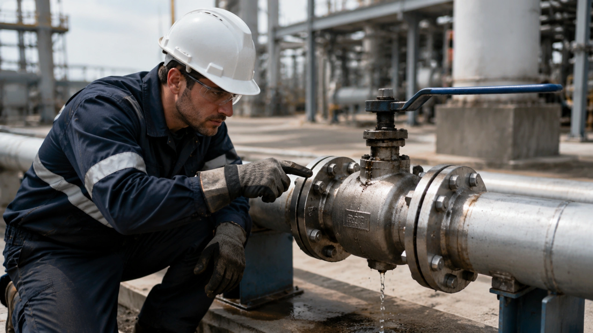
Practical Selection Checklist
| Selection Factor | Recommended Check |
|---|---|
| Design pressure | Check valve and flange pressure-temperature rating at design temperature. |
| Design temperature | Confirm material derating, gasket limit, sealant limit, and thermal expansion. |
| Media hazard | For toxic, flammable, hydrogen, or sour service, evaluate leakage consequence and owner restrictions. |
| Maintenance frequency | Use flanged or clamp connections where frequent removal is required; avoid buttweld unless leakage risk dominates. |
| Leakage consequence | Evaluate RTJ or buttweld for severe service where gasket leakage is unacceptable. |
| Pipe matching | For buttweld ends, verify material, schedule, bevel, toughness, and welding procedure. |
| Inspection | Define NDT method, coverage, acceptance criteria, hardness test, and leak-test method. |
| Project specification | Always check owner standards, local regulations, and applicable code edition. |
Conclusion
Flanged, buttweld, threaded, and clamp connections each have a valid place in industrial valve selection.
Flanged connections are the most maintainable and widely used option for general process and utility service, but gasket and bolt preload create potential leakage paths. RTJ flanges should be evaluated for severe high-pressure or high-temperature services where leakage consequence is high.
Buttweld connections remove the gasketed valve end-joint leakage path and are often preferred for high-pressure, high-temperature, hydrogen, toxic, flammable, buried, or difficult-access service. Their main disadvantage is that valve removal usually requires cutting and rewelding.
NPT threaded connections are compact and economical, but they should normally be limited to small-bore, low-risk service where vibration, temperature, reuse, and leakage consequences are acceptable.
Clamp quick-connect connections are excellent for sanitary and frequently cleaned systems, but their pressure and temperature capability must be verified from clamp, ferrule, and gasket manufacturer data.
The best valve end connection is selected by engineering judgment, not by habit. A reliable specification should check pressure-temperature rating, flange face, gasket type, weld-end preparation, pipe matching, maintenance frequency, leakage consequence, and inspection requirements before purchase.
References
- ASME PCC-1, Pressure Boundary Bolted Flange Joint Assembly
- ISO 15848-2, Industrial Valves — Fugitive Emissions — Production Acceptance Test
- ASME B16.5, Pipe Flanges and Flanged Fittings
- ASME B16.34, Valves — Flanged, Threaded, and Welding End
- ASME B16.25, Buttwelding Ends
- ASME B31.3, Process Piping
- ASME B1.20.1, Pipe Threads, General Purpose, Inch
- ASME BPE, Bioprocessing Equipment


")